Sign In
Upload
Manuals
Brands
Allen-Bradley Manuals
Engine
Kinetix 6000M
Allen-Bradley Kinetix 6000M Manuals
Manuals and User Guides for Allen-Bradley Kinetix 6000M. We have
1
Allen-Bradley Kinetix 6000M manual available for free PDF download: User Manual
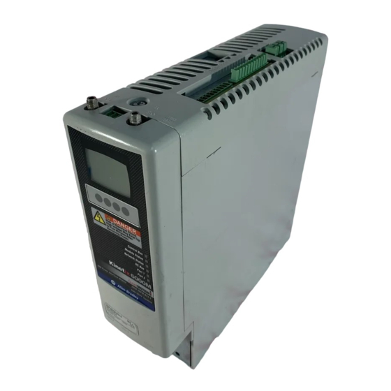
Allen-Bradley Kinetix 6000M User Manual (144 pages)
Integrated Drive-Motor System
Brand:
Allen-Bradley
| Category:
Engine
| Size: 14 MB
Table of Contents
Table of Contents
3
About this Publication
7
Additional Resources
7
Conventions Used in this Manual
7
Chapter 1
9
About the Kinetix 6000M System
9
Typical Hardware Configurations
11
Typical Communication Configurations
16
Catalog Number Explanations
17
Component Compatibility
18
Agency Compliance
19
CE Requirements (System Without LIM Module)
19
CE Requirements (System with LIM Module)
19
Cable Length Restrictions and System Sizing
21
Chapter 2 IPIM Module Design Guidelines
22
System Mounting Requirements
22
Circuit Breaker/Fuse Options
23
Enclosure Selection
24
Minimum Clearance Requirements
25
IDM Unit Design Guidelines
26
Minimum Clearance Requirements
26
Electrical Noise Reduction
27
Cable Categories for Kinetix 6000M System
28
Mounting the IPIM Module
30
Using the 2094 Mounting Brackets
30
Installing the 2094 Power Rail
30
Determine Mounting Order
30
System on Page 103 for Details
30
Chapter 3 Mounting the Kinetix 6000M System Mounting the IPIM Module
30
Mount the IPIM Module
32
Installing the IDM Unit
33
Aligning the IDM Unit
34
Mount and Connect the IDM Unit
34
IPIM Module Connectors and Indicators
38
Chapter 4 IPIM Module Connector and Signal Descriptions
39
Hybrid Cable DC Bus Connector
39
Hybrid Cable Communication Signals Connector
39
Safe Torque-Off Connector
40
Sercos Fiber-Optic Connectors
41
Enable Input
41
Ethernet/Ip Connectors
42
IPIM Module Network Connector Pinouts
42
IDM Unit Connectors and Indicators
43
IDM Unit Connector and Signal Descriptions
44
Hybrid Cable Connector
44
IDM Network Input and Output Connector Pinouts
45
Digital Input Connectors
45
Power Specifications
50
Brake Override Input
50
Peak Duty Cycle
50
Feedback Specifications
52
Absolute Position
52
Basic Wiring Requirements
53
Chapter 5 Routing the Power and Signal Cables
54
Grounding the IDM System
54
Apply the Cable Shield Clamp
55
General IDM System Wiring
56
Hybrid Cable
56
Network Cable
58
How to Bypass an IDM Unit
58
The Sercos Fiber-Optic Ring
59
Ethernet Cable Connections
63
Rockwell Automation Publication 2094-UM003A-EN-P - May
64
Configure the Kinetix 6000M Integrated Drive-Motor System
65
Chapter 6 Understanding the IPIM Module Display
66
Startup Sequence
67
Information Display
67
Tools Menu
68
Configuring the IPIM Module
69
Setting the IPIM Module Network Address
69
Configuring the IDM Unit
70
Setting the Node Address
70
Add-On Profiles
73
Configure the Logix Sercos Interface Module
73
Configure the Logix Controller
73
Configure the Logix Module
75
Configure the IDM Units
77
Configure the Motion Group
79
Configure Axis Properties
80
Download the Program
81
Apply Power to the System
82
Test and Tune the Axes
83
Test the Axes
83
Tune the Axes
85
Safety Precautions
87
Chapter 7 IDM System Error Codes
87
Reading the Fault Status of the IPIM Module
88
Interpret Status Indicators
90
IPIM Module Status Indicators
90
IDM Unit Status Indicators
91
General System Anomalies
92
IPIM Module Fault Diagnosis
93
IPIM Module Fault Types
94
IDM Unit Fault Diagnosis
95
Logix Controller/IDM Unit Fault Behavior
95
Use a Web Browser to Monitor System Status
97
Before You Begin
99
Chapter 8
100
Remove the IPIM Module
100
Replace the IPIM Module
101
Certification
103
Appendix A
103
Important Safety Considerations
103
Category 3 Requirements According to en ISO 13849-1
104
Stop Category Definition
104
Performance Level (PL) and Safety Integrity Level (SIL)
104
Description of Operation
104
Troubleshooting the Safe Torque-Off Function
105
PFD, PFH, and Mttfd Definitions
107
PFD, PFH, and Mttfd Data
107
Wiring Your Safe Torque-Off Circuit
107
European Union Directives
108
IDM Safe Torque-Off Feature
108
Safe Torque-Off Feature Bypass
109
IDM System Safe Torque-Off Example
109
Cascading the Safe Torque-Off Signal
110
Safe Torque-Off Signal Specifications
111
Appendix B
114
Before You Begin
115
Appendix C
116
Configure Logix Communication
116
IPIM Module Firmware Upgrade
117
IDM Unit Firmware Upgrade
121
Verify the Firmware Upgrade
125
Definitions
127
Appendix D
128
Manually Sizing the Kinetix 6000M System
128
Rockwell Automation Publication 2094-UM003A-EN-P - May
129
Advertisement
Advertisement
Related Products
Allen-Bradley Kinetix 6000
Allen-Bradley Kinetix 5700
Allen-Bradley Kinetix 5500 series
Allen-Bradley Kinetix 5700 Series
Allen-Bradley Kinetix 2000
Allen-Bradley MPL-A310
Allen-Bradley MPL-A320
Allen-Bradley MPL-A330
Allen-Bradley MPL-A420
Allen-Bradley MPL-A430
Allen-Bradley Categories
Control Unit
Controller
I/O Systems
Switch
Power Supply
More Allen-Bradley Manuals
Login
Sign In
OR
Sign in with Facebook
Sign in with Google
Upload manual
Upload from disk
Upload from URL