Sign In
Upload
Manuals
Brands
Agilent Technologies Manuals
Water Pump
1260 Infinity II Series
Agilent Technologies 1260 Infinity II Series Manuals
Manuals and User Guides for Agilent Technologies 1260 Infinity II Series. We have
2
Agilent Technologies 1260 Infinity II Series manuals available for free PDF download: User Manual
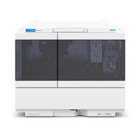
Agilent Technologies 1260 Infinity II Series User Manual (326 pages)
Vialsamplers
Brand:
Agilent Technologies
| Category:
Laboratory Equipment
| Size: 7.83 MB
Table of Contents
Table of Contents
5
Introduction
9
Product Description (G7129A)
10
Features (G7129A)
11
Product Description (G7129B)
12
Features (G7129B)
13
Product Description (G7129C)
14
Features (G7129C)
15
Overview of the Module
16
Operating Principle
18
Sampling Sequence
18
Needle Parkstation
23
Hydraulic Box
24
Transport Assembly
26
Leak and Waste Handling
28
Leak Sensor
32
Waste Guidance
32
Waste Concept
33
2 Site Requirements and Specifications
35
Site Requirements
36
Physical Specifications
40
Performance Specifications
41
Performance Specifications (G7129A)
41
Performance Specifications (G7129B)
43
Performance Specifications (G7129C)
45
Specifications of the Sample Cooler
47
Specifications of the Sample Thermostat
49
Specifications of the Integrated Column Compartment
51
3 Using the Module
53
Magnets
54
Turn On/Off
55
Status Indicators
57
Exchange Drawers
58
Install the Integrated Column Compartment
60
Install the Column Shelf
66
Install the External Tray
70
Install a Column (ICC)
72
Remove a Column (ICC)
76
Sample Trays
78
Choice of Vials and Caps
81
Transporting the Sampler with a Sample Cooler or Sample Thermostat Installed
84
Agilent Local Control Modules
86
4 Installation of the Optional Sample Cooler or Thermostat
89
Damaged Packaging
90
Install the Sample Cooler or Thermostat
91
Using the Sample Cooler or Thermostat in an Infinity II Sampler
97
Control Interface
98
Control
99
Temperature Mode
100
Online Signal Monitor
101
Operation Information
102
Important Information
103
5 Preparing the Module
105
Leak and Waste Handling
106
Preparing the Module
107
Solvent Information
108
Capillary Color Coding Guide
114
Installing Capillaries
115
Flow Connections to the Vialsampler
117
Setting up the Vialsampler
119
Control Settings
122
Method Parameter Settings
124
Injector Programm
128
Module Configuration View
129
6 Optimizing Performance
131
Optimization for Lowest Carry-Over
132
Using the Automated Needle Wash (Wash Port)
132
Using an Injector Program
134
General Recommendation to Lowest Carry-Over
135
Fast Injection Cycle and Low Delay Volume
136
Overlapped Injection Mode
136
General Recommendations for Fast Injection Cycle Times
137
Precise Injection Volume
138
Draw and Eject Speed
138
Choice of Rotor Seal
140
7 Troubleshooting and Diagnostics
141
Overview of the Module's Indicators and Test Functions
142
Maintenance Functions
144
User Interface
144
Change Needle
145
Change Metering Seal or Piston
147
Park Arm
148
Change Gripper
150
Automatic Referencing
151
Vialsampler Gripper Verification Test
152
Step Commands
153
Tests
155
ICC Heater Test
155
Sample Cooler Function Test
155
Troubleshooting
156
Troubleshooting Guide for the Sample Transport Assembly
158
Intermittent Lock-Ups with or Without Vial in the Gripper Fingers
159
Poor Alignment
160
Agilent Lab Advisor Software
161
8 Error Information
163
What Are Error Messages
165
General Error Messages
166
Timeout
166
Shutdown
166
Remote Timeout
167
Lost CAN Partner
167
Leak Sensor
168
Leak Sensor Open
169
Leak Sensor Short
169
Compensation Sensor Open
170
Compensation Sensor Short
170
Fan Failed
171
Sampler Error Messages
172
Defective Gripper Assembly
172
Valve Failed
172
Needle Movement Failed
173
Missing Vial
173
Initialization Failed
174
Metering Home Failed
175
Motor Temperature
176
Initialization with Vial
177
Vial in Gripper
177
Missing Wash Vial
178
Invalid Vial Position
178
Valve Switch Not Found
179
Metering Initialization Failed
179
Sample Cooler Error Messages
180
Cooler Voltage Failure
180
Cooler PCB Error State
180
Cooler Temperature below or above Target Temperatur
181
Cooler Overpressure Failure
181
Cooler Condensate Error
182
Integrated Column Compartment (ICC) Heater Error Messages
183
ICC Temp Wait Timeout Error
183
ICC Heater Overcurrent Failure
183
ICC Heater Temp Sensor Failure
184
ICC Heater over Temp Failure
184
9 Maintenance and Repair
185
Introduction to Maintenance
186
Warnings and Cautions
187
Overview of Maintenance
189
Cleaning the Module
190
Remove and Install Doors
191
Exchange the Needle Assembly
192
Exchange the Needle Seat Assembly
197
Exchange the Sample Loop Assembly
202
Exchange the Rotor Seal
206
Exchange the Metering Seal and Piston
212
Exchange the Gripper Arm
216
Replace the Peristaltic Pump Cartridge
219
Exchange the Wash Port Assembly
222
Replace the Module Firmware
228
10 Parts and Materials for Maintenance
229
Main Assemblies
230
Standard Parts
232
Drawer Assembly
233
External Tray
235
Analytical Head Assembly (40 Μl)
236
Analytical Head Assembly (100 Μl)
237
2Ps 6Pt Injection Valve 1300 Bar
238
2Ps 6Pt Injection Valve 800 Bar
239
2Ps 6Pt Injection Valve 600 Bar
240
Integrated Column Compartment
241
Cabinet Kit
242
Sample Thermostat
244
Standard Vialsampler Accessory Kit
246
Multi-Draw Kit
248
Additional Part List
249
Column Identifier Kit 2C (G4751A)
250
Identifying Cables
251
Cable Overview
252
Analog Cables
254
Remote Cables
256
CAN/LAN Cables
260
RS-232 Cables
261
Usb
262
12 Hardware Information
263
Firmware Description
264
Electrical Connections
267
Rear View of the Module
268
Serial Number Information
268
Interfaces
269
Overview Interfaces
271
ERI (Enhanced Remote Interface)
274
USB (Universal Serial Bus)
276
Setting the 6-Bit Configuration Switch
277
Special Settings
279
Instrument Layout
281
Early Maintenance Feedback (EMF)
282
13 LAN Configuration
283
LAN Configuration What You Have to Do First
284
TCP/IP Parameter Configuration
285
Configuration Switches
286
Initialization Mode Selection
287
Dynamic Host Configuration Protocol (DHCP)
289
General Information (DHCP)
289
Setup (DHCP)
290
Manual Configuration
292
With Telnet
293
PC and Agilent Chemstation Setup
297
PC Setup for Local Configuration
297
Agilent Chemstation Setup
300
14 Appendix
307
General Safety Information
308
Safety Standards
308
General
308
Before Applying Power
309
Ground the Instrument
309
Do Not Modify the Instrument
310
Do Not Operate in an Explosive Atmosphere
310
Do Not Remove the Instrument Cover
310
In Case of Damage
310
Solvents
311
Symbols
312
Waste Electrical and Electronic Equipment (WEE) Directive
314
Refrigerant
315
Radio Interference
318
Sound Emission
319
Solvent Information
320
Agilent Technologies on Internet
321
Advertisement
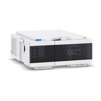
Agilent Technologies 1260 Infinity II Series User Manual (262 pages)
Isocratic and Quaternary Pumps
Brand:
Agilent Technologies
| Category:
Water Pump
| Size: 4.69 MB
Table of Contents
Table of Contents
5
Introduction
9
Introduction to the Pump
10
G7110B Isocratic Pump
11
Product Description
11
Features
12
G7111A Quaternary Pump VL
13
Product Description
13
Features
14
G7111B Quaternary Pump
15
Product Description
15
Features
16
G5654A Bio-Inert Pump
17
Product Description
17
Features
18
Overview of the Hydraulic Path
19
Hydraulic Path
20
How Does the Pump Work
22
How Does Compressibility Compensation Work
25
How Does Variable Stroke Volume Work
26
Leak and Waste Handling
27
Leak Sensor
31
Waste Concept
31
2 Site Requirements and Specifications
33
Site Requirements
34
Physical Specifications
37
Physical Specifications Agilent 1260 Infinity II Isocratic Pump (G7110B)
37
Physical Specifications Agilent 1260 Infinity II Quaternary Pump VL (G7111A)
38
Physical Specifications Agilent 1260 Infinity II Quaternary Pump (G7111B)
39
Physical Specifications Agilent 1260 Infinity II Bio-Inert Pump (G5654A)
40
Performance Specifications
41
3 Using the Pump
49
Magnets
50
Turn On/Off
51
Status Indicators
53
Best Practices
54
Daily / Weekly Tasks
54
Power up / Shut-Down the Pump
54
Prepare the Pump
55
How to Deal with Solvents
56
Select Channels for Multi-Channel Gradient Valve (MCGV)
56
Leak and Waste Handling
57
Waste Concept
58
Hints for Successful Use of the Pump
59
Setting up the Pump with the G4208A Instant Pilot
60
Setting up the Pump with the Instrument Control Interface
61
Overview
61
Instrument Configuration
62
The Pump User Interface (Dashboard Panel)
63
Control Settings
66
Method Parameter Settings
67
Solvent Information
71
Materials in Flow Path
72
Bio-Inert Materials
74
Material Information
76
Algae Growth in HPLC Systems
81
How to Prevent And/Or Reduce the Algae Problem
81
Prevent Blocking of Solvent Filters
82
Normal Phase Applications
83
4 Optimizing Performance
85
Using the Degasser
86
Operational Hints for the Vacuum Degasser
87
Operational Hints for the Multi Channel Gradient Valve (MCGV)
88
When to Use the Seal Wash Function
89
Choosing the Right Pump Seals
90
Optimize the Compressibility Compensation Setting
91
Troubleshooting and Diagnostics
93
User Interfaces
94
Agilent Lab Advisor Software
95
6 Error Information
97
What Are Error Messages
99
General Error Messages
100
Timeout
100
Shutdown
101
Remote Timeout
101
Lost CAN Partner
102
Leak
102
Leak Sensor Open
103
Leak Sensor Short
103
Compensation Sensor Open
104
Compensation Sensor Short
104
Fan Failed
105
ERI Messages
105
Module Error Messages
106
Solvent Zero Counter
106
Pressure above Upper Limit
107
Pressure below Lower Limit
108
Pressure Signal Missing
109
MCGV Fuse
109
AIV Fuse
110
Valve Failed (MCGV)
111
Motor-Drive Power
112
Servo Restart Failed
113
Pump Head Missing
114
Index Limit
114
Index Adjustment
115
Index Missing
115
Initialization Failed
116
Wait Timeout
117
Degasser: Signal Fail
118
Degasser: Vacuum Cannot be Maintained
118
Degasser: Limit Not Reached
119
SSV Protection Circuit Triggered
119
7 Test Functions and Calibration
121
Introduction
122
System Pressure Test
123
Running the Test
125
Evaluating the Results
126
Potential Causes of System Pressure Test Failure
127
Leak Rate Test
128
Running the Test
130
Evaluating the Results
131
Potential Causes of Leak Rate Test Failure
132
8 Maintenance
135
Introduction to Maintenance and Repair
136
Warnings and Cautions
137
Overview of Maintenance and Repair
138
Cleaning the Module
139
Remove and Install Doors
140
Checking and Replacing the Solvent Filter
141
Exchange the Passive Inlet Valve
142
Exchange the Outlet Valve
144
Exchange the Purge Valve Frit or the Purge Valve
146
Replace the O-Ring on the Purge Valve
150
Remove the Pump Head Assembly
153
Maintenance of a Pump Head Without Seal Wash Option
155
Maintenance of a Pump Head with Seal Wash Option
158
Reinstall the Pump Head Assembly
162
Seal Wear-In Procedure
165
Exchange the Multi-Channel Gradient Valve (MCGV)
166
Replace the Solvent Selection Valve (Isocratic Pump)
169
Exchange the Active Inlet Valve (AIV) or Its Cartridge
171
Exchange the Seal Wash Cartridge
173
Replace Leak Handling System Parts
174
Replacing the Module Firmware
175
9 Parts for Maintenance
177
Accessory Kits
178
Pump Head Assembly Without Seal Wash
180
Pump Head Assembly with Seal Wash Option
182
Outlet Valve
185
Purge Valve Assembly
186
Active Inlet Valve Assembly
188
1260 Infinity II Max Uptime Kit
190
1260 Infinity II Max Uptime Kit Bio
191
1260 Infinity II Low Dispersion Kit MCT
192
HPLC System Tool Kit
193
Solvent Cabinet
194
Bottle Head Assembly
195
Hydraulic Path of the Quaternary Pump
196
Hydraulic Path of the Isocratic Pump
198
10 Identifying Cables
201
Cable Overview
202
Analog Cables
204
Remote Cables
206
CAN Cable
210
Agilent Module to PC
211
Agilent 1200 Module to Printer
212
11 Hardware Information
213
Firmware Description
214
Electrical Connections
217
Serial Number Information
218
Rear View of the Module
218
Interfaces
219
Overview Interfaces
221
ERI (Enhanced Remote Interface)
224
USB (Universal Serial Bus)
226
Setting the 6-Bit Configuration Switch
227
Special Settings
229
Instrument Layout
231
Early Maintenance Feedback
232
12 LAN Configuration
233
LAN Configuration What You Have to Do First
234
TCP/IP Parameter Configuration
235
Configuration Switches
236
Initialization Mode Selection
237
Dynamic Host Configuration Protocol (DHCP)
239
General Information (DHCP)
239
Setup (DHCP)
240
Manual Configuration
242
With Telnet
242
13 Appendix
247
General Safety Information
248
Safety Standards
248
General
248
Before Applying Power
249
Ground the Instrument
249
Do Not Modify the Instrument
250
Do Not Operate in an Explosive Atmosphere
250
Do Not Remove the Instrument Cover
250
In Case of Damage
250
Solvents
251
Safety Symbols
252
Waste Electrical and Electronic Equipment (WEE) Directive
254
Radio Interference
255
Sound Emission
256
Agilent Technologies on Internet
257
Advertisement
Related Products
Agilent Technologies 1260 Infinity Quaternary LC VL
Agilent Technologies 1290 infinity
Agilent Technologies 1260 Infinity
Agilent Technologies Turbo-V 1K-G Series
Agilent Technologies 19-1510
Agilent Technologies 19-1520
Agilent Technologies 19-1540
Agilent Technologies 1260Infinity II Bio-inert FractionCollector
Agilent Technologies 1260 Infinity II
Agilent Technologies 1260 Infinity II AnalyticalFraction Collector
Agilent Technologies Categories
Measuring Instruments
Laboratory Equipment
Test Equipment
Water Pump
Power Supply
More Agilent Technologies Manuals
Login
Sign In
OR
Sign in with Facebook
Sign in with Google
Upload manual
Upload from disk
Upload from URL