Muratec MFX-1330 Field Engineering Manual
Hide thumbs
Also See for MFX-1330:
- User manual (189 pages) ,
- Specifications (2 pages) ,
- Specification sheet (2 pages)
Table of Contents
Advertisement
Quick Links
Download this manual
See also:
User Manual
Advertisement
Table of Contents

Related Manuals for Muratec MFX-1330


Summary of Contents for Muratec MFX-1330
- Page 1 Muratec MFX-1330 / F-300 FACSIMILE SYSTEM FIELD ENGINEERING MANUAL U.S.A. version 2.0 Muratec America, Inc. 3301 East Plano Parkway, Ste. 100 Plano, Tx 75074 (469) 429-3300 (Tel) (469) 429-3465 (Fax) www.muratec.com...
-
Page 3: Safety Information
Replace only with the same or equivalent type recommended by the manufacturer. Dispose of used batteries according to the manufacturer’s instructions. Important: Muratec does not recommend the independent replacement of this battery. The battery is sold only as a component part of the main control PCB and Battery PCB, and cannot be purchased separately from Muratec. - Page 4 Sweden only VARNING Explosionsfara vid felaktigt batteribyte. Använd samma batterityp eller en ekvivalent typ som rekommenderas av apparattillverkaren. Kassera använt batteri enligt fabrikantens instruktion. Finland only VAROlTUS Paristo voi räjähtää, los se on virheellisesti asennettu. Vaihda paristo ainoastaan laitevalmistajan suosittelemaan tyyppiin. Hävitä...
-
Page 5: Table Of Contents
2.5.1 Sensor Locations .......................... 2-6 2.5.2 Sensor Descriptions........................2-7 2.6 Document Scanning Sequence ......................2-8 2.6.1 ADF Detection ..........................2-8 2.6.2 FBS section (MFX-1330 only) ...................... 2-9 2.7 Recording Section..........................2-11 2.7.1 Recording Paper Feed Path ....................... 2-11 2.8 Image Processing ..........................2-12 2.8.1 Drum Charge .......................... - Page 6 4.2 Recording Paper Jam .......................... 4-2 4.3 Document Feeder Jam ........................4-2 4.4 Document Feeder Multi-feeding or Skew .................... 4-3 4.5 Mirror Carriage Error (MFX-1330 only)....................4-3 4.6 Transmit Error ............................4-3 4.7 Transmit Black Lines..........................4-3 4.8 Cannot transmit............................ 4-4 4.9 Receive Errors .............................
- Page 7 5.3.12 ADF registration (side)......................5-82 5.3.13 SEPARATION PRESSURE ADJUSTMENT ................5-83 5.3.14 Cleaning the MIRRORS A, B and C ..................5-84 5.3.15 Applying the SHEET DOCUMENT PRESS (MFX-1330 only)..........5-85 Section 6 Options..............6-1 6.1 Memory Upgrade ..........................6-1 Packaging contents: ..........................6-1 Installation..............................
- Page 8 6.6 Second phone line kit......................... 6-11 Packaging contents: ..........................6-11 Installation............................6-11...
-
Page 9: Section 1 General Description
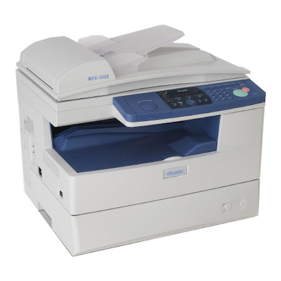
Section 1 General Description 1.1 Product Description The MFX-1330 and F-300 are Multi-function products with flat bed scanner (MFX-1330) and Group 3 and V.34 HDX modem facsimile machine. Documents are printed on plain paper using dry electrophotographic printing. Automatic Document... -
Page 10: Specifications
600 lpi Effective Scanning width 208 mm (Fax), 216 mm (Copy) Transmission speed Under 3 seconds (Super G3) Based on transmission of ITU-T Test Document 1 to a Muratec fax machine. Document Memory Standard: 8 MB (650 pages) Upgrade option:... - Page 11 Item MFX-1330 F-300 Printing speed Simplex printing: 13 ppm 13 ppm (When loading Letter- Duplex printing : 5 ppm sized paper from 1st paper (When loading Letter-sized paper cassette.) from 1st paper cassette.) Toner yield Approx. 5,000 pages Approx. 7,500 pages...
- Page 12 Item MFX-1330 F-300 Dimensions Standard: 520mm (W) 450 mm (D) 446 mm (H) With optional cassette: 520mm (W) 450 mm (D) 566 mm (H) 520 mm 520 mm Weight Approx. 21.1 Kg (46.5 lbs) without Approx. 19.0 Kg (41.9 lbs) without consumables and trays.
-
Page 13: Section2 Machine Composition
Section2 Machine Composition 2.1 Interconnect Block Diagram (1/2) 1T(flat) CLK-P CLK-N +3.3DP +3.3DP LOAD DC/DC HSYNC DA7-08130-50 VDD3 DATA3 CONNECT +24V DATA2 +24V DATA1 LED HEAD 80x50 DATA0 /STROBE Option (simplex side) STROBE DATA1 DA7-08450-50A DATA2 DATA3 DA7-08100-50 DATA4 +3.3V LINE DCB-xyyzz-50A LED_GND... - Page 14 Interconnect Block Diagram (2/2) 1T(flatA) 1T(flat) 52271 +12V (molex) +12V BW/COL PRXD PLOAD PANEL DA7-08020-50 Z90-37777-50 330 x 87 DCB-70306-50A +24V (simplex side) LSCK ZA1-02394-20 LEDWR1 LEDWR2 SCAN-LAMP 90mm (FFC) 16 16 /OTCH1 DA7-08030-50 DA7-08300-40C /OTCH2 PSAVE 35 x 176 DA7-08470-50B SPEAKER CLM1...
-
Page 15: Main Control Pcb
2.2 Main Control PCB The main control PCB controls the operations of all machine functions. Jumper JP2 on the main control PCB is used for battery back up of the SDRAM. Removing JP2 will initialize the SDRAM. If the power is turned off, the battery will provide up to 72 hours (8MB) of back up when fully charged. -
Page 16: Network Control Unit (Ncu) Pcb
2.3 Network Control Unit (NCU) PCB The NCU PCB provides the connection to the telephone line. It consists of the interface circuit, ring signal detector and telephone control circuit. NCU PCB block diagram Major components of the NCU DP relay Connects the telephone line to the fax. -
Page 17: Power Supply Unit (Psu)
2.4 Power Supply Unit (PSU) The power supply unit receives the input line voltage and currents it to output voltages of +5 VDC, +24 VDC, +12 VDC, and -12 VDC. The heater circuit controls output voltage to the fuser heater according to instructions received from the heater control circuit. -
Page 18: Sensors
2.5 Sensors 2.5.1 Sensor Locations The following illustration shows the relative positions of the machine’s sensors. PES1 JAMC2 OPEN2 PES2 TXIL COVER-SW JAMC1 Thermistor OPEN1 TRAYS... -
Page 19: Sensor Descriptions
Paper discharge Detects paper pass at paper Photo sensor exit. interrupter Duplex paper sensor Detects paper pass of the Photo MFX-1330 only duplex printing paper interrupter Thermistor ---- Detects and controls the Thermistor Heater Roller temperature OPEN1 Paper cassette open... -
Page 20: Document Scanning Sequence
When DS2 detects the trailing edge of the document, the image signal output is turned off. The scanner continues to remain active for a few more seconds in case there is another document to follow. The scanned document is discharged through the document exit by the exit roller. MFX-1330 Pickup roller Separator roller... -
Page 21: Fbs Section (Mfx-1330 Only)
2.6.2 FBS section (MFX-1330 only) Light reflected from the original passes through three mirrors and a lens to form a reduced image on the CCD Sensor as the Scanner Motor moves the Scanner. The CCD sensor converts the light pattern (image data) into an electrical image signal. - Page 22 2.6.2.2 Scanner frame Moving Mechanism During a scan, the scanner frame projects an even amount of light from the Exposure Lamp onto the entire surface of the original. The light is reflected from the original to the Mirror through the lens to the CCD.
-
Page 23: Recording Section
The paper is moved along the paper guide until it reaches the register roller. Is then fed by the rotation of the register roller. MFX-1330 can print both sides of the paper (duplex printing). When the first side of the paper is printed, it is transferred to the exit. However after a few steps after the PDS and DPS sensor detected the trailing edge, the exit roller rolls in reverse and the paper is transferred to the image processing area by the duplex rollers. -
Page 24: Image Processing
2.8 Image Processing Incoming data is received from the telephone line by the NCU and sent to the main control PCB. The modem, located on the main control PCB, demodulates the data. The data is then sent to the printer for image processing. The image processing is roughly divide into the following steps: 1. -
Page 25: Development
2.8.3 Development Toner is applied to the invisible static image on the Drum and a toner image is created on the surface. Toner agitator Drum Developing roller Toner supply roller Part Name Function Toner Agitator Agitates toner. Toner supply Roller Transports the toner to the developing roller. -
Page 26: Erasing
2.8.5 Erasing An LED lamp exposes the Drum surface. When it is exposed the drum charge erases. This helps the drum to be recharged evenly at the next step of charging. Drum LED Lamp 2.8.6 Cleaning The residual toner or paper dust must be removed from the drum. Paper dust is removed from the drum surface by a rubber roller. -
Page 27: Fusing
2.8.7 Fusing An Overview The toner image transferred on to the paper is securely fixed. A heat roller system is used as the fusing system. The toner image is fused by Heater Roller heated by the Heater Lamp, and securely fixed by the pressure between the Heater roller and Press rollers. A Thermistor detects and controls the Heater Roller temperature. - Page 28 Fusing Temperature Control Circuit The Thermistor detects the surface temperature of the Heater Roller and inputs that analog voltage into the Main Control PCB. Corresponding to this data, the Heater Lamp ON/OFF signal is output to the Heater ON/OFF switch of the power supply unit, causing the Heater Lamp to turn ON or OFF to control the fusing temperature.
-
Page 29: Field Service Program Modes
Section3 Adjustment Procedures 3.1 Field Service Program Modes The fax machine feature maintenance modes for machine adjustment. Each mode is listed below along with the command used to activate the mode and a brief functional description. Note: When you press “ * ”, you will hear short beeps. However continue the operation, as there is no problem. - Page 30 Printer diagnostic mode ....................MENU, *, 2, 3 Printer diagnostic test. Network service mode ......................MENU, *, 2, 4 Used to display the server sumcheck or to initialize the network settings, when an optional network board is installed. Set second line ........................MENU, *, 2, 8 Used to set memory switches, unique switches, ECM mode, pose length and numbers of rings for the second telephone line.
-
Page 31: Machine Parameter Adjustment
3.2 Machine Parameter Adjustment 3.2.1 Setting the Machine Parameters These switches are used to program internal machine parameters. The primary back up battery maintains these settings if power is lost. 1. From standby, press MENU, *, 0, 0. Set Parameters / /Enter 2. - Page 32 1 step = 2 / 600 dpi (0.0847 mm) 00000000 0 mm Initial setting Note: These values 10001000 -0.68 mm are factory set and should not be adjusted unless 10010000 -1.36 mm instructed by a Muratec technical representative. 10100000 -2.71 mm -127steps 11111111 -10.76 mm...
- Page 33 Initial setting 10000001 -0.1 % Note: These values are 10000010 -0.2 % factory set and should not be adjusted unless instructed by 10000100 -0.4 % a Muratec technical representative. 10001000 -0.8 % 10001111 -1.5 % Machine Parameter 012 Initial Switch Adjust...
- Page 34 00000000 15.6 mm 10001000 -0.68 mm Note: These values are factory set and should 10010000 -1.36 mm not be adjusted unless instructed by a Muratec 10100000 -2.71 mm technical representative. 100111111 -5.34 mm Initial setting -127steps 11111111 -10.76 mm Machine Parameter 014...
- Page 35 0 mm Note: These values 10000010 -0.17 mm Initial setting are factory set and should not be adjusted unless 10001000 -0.68 mm instructed by a Muratec technical representative. 10010000 -1.36 mm 10100000 -2.71 mm -127steps 11111111 -10.76 mm Machine Parameter 016...
- Page 36 8 steps 00001000 +0.17 mm Note: These values are factory set and should not be 00000000 21.85 mm adjusted unless instructed by a Muratec technical -8 steps 10001000 -0.17 mm representative. -12 steps 10001100 -0.25 mm Initial setting -16 steps 10010000 -0.34 mm...
- Page 37 +2.82 mm Note: These values 10 steps 00001010 +1.41 mm are factory set and should not be adjusted unless 3 steps 00000011 +0.42 mm instructed by a Muratec 2 steps 00000010 +0.28 mm technical representative. 1 step 00000001 +0.14 mm 00000000 9.15 mm...
- Page 38 Machine Parameter 025 Initial Switch Adjust Usage/Comments Setting Background level adjustment Switch 76543210 Settings starting position 127steps 01111111 +2.70 mm Adjusts the number of the steps from the home sensor 64 steps 01000000 +1.36 mm of the mirror carriage OFF to the background level 32 steps 00100000 +0.68 mm...
- Page 39 Machine Parameter 030 Initial Switch Adjust Usage/Comments Setting Scanning density level Switch 76543210 adjustment in normal 01111111 Darkest setting resolution. 00001000 00000000 Initial setting 10001000 11111111 Lightest setting Machine Parameter 031 Initial Switch Adjust Usage/Comments Setting Scanning density level Switch 76543210 adjustment in fine resolution.
- Page 40 Machine Parameter 033 Initial Switch Adjust Usage/Comments Setting Scanning density level Switch 76543210 adjustment in hyper-fine 01111111 Darkest setting resolution. 00001000 00000000 Initial setting 10001000 11111111 Lightest setting Machine Parameter 034 Initial Switch Adjust Usage/Comments Setting Scanning density level Switch 76543210 adjustment in hyper-fine 01111111 Darkest setting...
- Page 41 Machine Parameter 090 Initial Switch Adjust Usage/Comments Setting Able to use the bypass tray When set to “1”, the cassette is not available in fax in normal fax reception. reception. 0: Yes 1: No Note: This setting does not affect the rotate fax reception.
- Page 42 Machine Parameter 100 Initial Switch Adjust Usage/Comments Setting Printer registration adjustment (Horizontal) at See table on page 3-18. the 1st cassette for printing. Note: Set this switch after setting the margin to Adjusts the start point to “0 mm” in Unique Switch 52. Then, after setting print.
- Page 43 Machine Parameter 108 Initial Switch Adjust Usage/Comments Setting Printer registration adjustment (Horizontal) for See table on page 3-18. duplex printing cassette. Note: Set this switch after setting the margin to Adjusts the start point to “0 mm” in Unique Switch 52. Then, after setting this switch, set the margin to the initial setting (4 print.
- Page 44 Machine Parameter 142 ∼ 146 --- Factory use only Machine Parameter 147 Initial Switch Adjust Usage/Comments Setting Printer registration adjustment. See table on page 3-18. Adjusts the left margin at the Note: The surrounding margin (right / left / top / Bypass tray for printing.
- Page 45 Machine Parameter 161 Initial Switch Adjust Usage/Comments Setting Printer registration adjustment. See table on page 3-18. Adjusts the right margin at Note: The surrounding margin (right / left / top / the 2nd cassette for printing. bottom) is set in Unique Switch 52. If you want to adjust only right margin, adjust it in this switch.
- Page 46 Adjusting the print margin Switch(76543210) Settings 01111111 +12.87mm 01111110 +11.52 mm 01100101 +10.84 mm 01100110 +10.16 mm 01011111 +9.48 mm 01011000 +8.81 mm 01010010 +8.13 mm 01001011 +7.45 mm 01000100 +6.77 mm 00111101 +6.10 mm 00110111 +5.42 mm 0011000 +4.74 mm 00101001 +4.06 mm 00010010...
- Page 47 Machine Parameter 180 Initial Switch Adjust Usage/Comments Setting Printer registration Switch 76543210 Settings adjustment (Vertical) at the 1st cassette for printing. 127 steps 01111111 +12.7 mm Adjusts the start point to 32 steps 00100000 +3.2 mm print. 16 steps 00010000 +1.6 mm The plus setting increases the top margin and the minus...
- Page 48 Machine Parameter 182 ∼ 186 --- Factory use only Machine Parameter 187 Initial Switch Adjust Usage/Comments Setting Printer registration Switch 76543210 Settings adjustment (Vertical) at the Bypass tray for printing. 127 steps 01111111 +12.7 mm Adjusts the start point to 32 steps 00100000 +3.2 mm...
- Page 49 Machine Parameter 220 Initial Switch Adjust Usage/Comments Setting Printer registration Switch 76543210 Settings adjustment. 127 steps 01111111 +12.7 mm Adjusts the top margin at the 1st cassette for printing. 32 steps 00100000 +3.2 mm The plus setting increases 16 steps 00010000 +1.6 mm the top margin and the minus...
- Page 50 Machine Parameter 222 ∼ 226 --- Factory use only Machine Parameter 227 Initial Switch Adjust Usage/Comments Setting Printer registration Switch 76543210 Settings adjustment. 127 steps 01111111 +12.7 mm Adjusts the top margin at the Bypass tray for printing. 32 steps 00100000 +3.2 mm The plus setting increases...
- Page 51 Machine Parameter 240 Initial Switch Adjust Usage/Comments Setting Printer registration Switch 76543210 Settings adjustment. 127 steps 01111111 +12.7 mm Adjusts the bottom margin at the 1st cassette for printing. 32 steps 00100000 +3.2 mm The plus setting decreases 16 steps 00010000 +1.6 mm the bottom margin and the...
- Page 52 Machine Parameter 242 ∼ 246 --- Factory use only Machine Parameter 247 Initial Switch Adjust Usage/Comments Setting Printer registration Switch 76543210 Settings adjustment. 127 steps 01111111 +12.7 mm Adjusts the bottom margin at the Bypass tray for printing. 32 steps 00100000 +3.2 mm The plus setting decreases...
- Page 53 Machine Parameter 285 Initial Switch Adjust Usage/Comments Setting Transfer current adjustment When transfer problems occur, adjust this for standard paper front side parameter. Switch 76543210 Settings +3.41 µA 31 steps 00011111 The plus setting increases +0.88 µA the current and the minus 8 steps 00001000 setting decreases it.
- Page 54 Machine Parameter 287 Initial Switch Adjust Usage/Comments Setting Transfer current adjustment When transfer problems occur, adjust this for postcards parameter. Switch 76543210 Settings +3.41 µA 31 steps 00011111 The plus setting increases +0.88 µA the current and the minus 8 steps 00001000 setting decreases it.
- Page 55 Machine Parameter 289 Initial Switch Adjust Usage/Comments Setting Transfer current adjustment When transfer problems occur, adjust this for standard paper back side parameter. Switch 76543210 Settings +3.41 µA 31 steps 00011111 The plus setting increases +0.88 µA the current and the minus 8 steps 00001000 setting decreases it.
- Page 56 Machine Parameter 461 Initial Switch Adjust Usage/Comments Setting White balance adjustment Switch 76543210 Copy/Black and white scan 16 steps 00010000 + Darkest setting mode Resolution: 600x600dpi 8 steps 00001000 Document type: Photo/Text Contrast: Dark, Darker, Light, 4 steps 00000100 Lighter 0 step 00000000 Standard...
- Page 57 Machine Parameter 463 Initial Switch Adjust Usage/Comments Setting White balance adjustment Switch 76543210 Copy/Black and white scan 16 steps 00010000 + Darkest setting mode Resolution: 600x600dpi 8 steps 00001000 Document type: Photo 4 steps 00000100 0 step 00000000 Standard -4 step 10000100 -8 step 10001000...
- Page 58 Machine Parameter 465 Initial Switch Adjust Usage/Comments Setting White balance adjustment Switch 76543210 Copy mode 16 steps 00010000 + Darkest setting Resolution: 600x300dpi Document type: Photo/Text 8 steps 00001000 Contrast: Dark, Darker, Light, Lighter 4 steps 00000100 0 step 00000000 Standard -4 step 10000100...
- Page 59 Machine Parameter 467 Initial Switch Adjust Usage/Comments Setting White balance adjustment Switch 76543210 Copy mode 16 steps 00010000 + Darkest setting Resolution: 600x300dpi Document type: Photo 8 steps 00001000 4 steps 00000100 0 step 00000000 Standard -4 step 10000100 -8 step 10000100 -16step 10000100...
- Page 60 Machine Parameter 469 Initial Switch Adjust Usage/Comments Setting White balance adjustment Switch 76543210 Black and White scan 16 steps 00010000 + Darkest setting Resolution: 300x300 dpi, 200x200dpi 8 steps 00001000 Document type: Photo/Text Contrast: Dark, Darker, Light, 4 steps 00000100 Lighter 0 step 00000000...
- Page 61 Machine Parameter 471 Initial Switch Adjust Usage/Comments Setting White balance adjustment Switch 76543210 Black and White scan 16 steps 00010000 + Darkest setting Resolution: 300x300 dpi, 200x200dpi 8 steps 00001000 Document type: Photo 4 steps 00000100 0 step 00000000 Standard -4 step 10000100 -8 step...
- Page 62 Machine Parameter 473 Initial Switch Adjust Usage/Comments Setting White balance adjustment Switch 76543210 Grayscale scan 16 steps 00010000 + Darkest setting Resolution: All 8 steps 00001000 4 steps 00000100 0 step 00000000 Standard -4 step 10000100 -8 step 10001000 -16step 10010000 Lightest setting The total step is the sum of Machine parameter...
- Page 63 Machine Parameter 475 Initial Switch Adjust Usage/Comments Setting White balance adjustment Switch 76543210 Fax mode 16 steps 00010000 + Darkest setting Document type: Gray scale 8 steps 00001000 4 steps 00000100 0 step 00000000 Standard -4 step 10000100 -8 step 10001000 -16step 10010000...
- Page 64 Machine Parameter 477 Initial Switch Adjust Usage/Comments Setting Black balance adjustment Switch 76543210 Copy/Black and white scan 16 steps 00010000 + Darkest setting mode Resolution: 600x600dpi 8 steps 00001000 Document type: Photo/Text Contrast: Dark, Darker, Light, 4 steps 00000100 Lighter 0 step 00000000 Standard...
- Page 65 Machine Parameter 479 Initial Switch Adjust Usage/Comments Setting Black balance adjustment Switch 76543210 Copy/Black and white scan 16 steps 00010000 + Darkest setting mode Resolution: 600x600dpi 8 steps 00001000 Document type: Photo 4 steps 00000100 0 step 00000000 Standard -4 step 10000100 -8 step 10001000...
- Page 66 Machine Parameter 481 Initial Switch Adjust Usage/Comments Setting Black balance adjustment Switch 76543210 Copy mode 16 steps 00010000 + Darkest setting Resolution: 600x300dpi Document type: Photo/Text 8 steps 00001000 Contrast: Dark, Darker, Light, Lighter 4 steps 00000100 0 step 00000000 Standard -4 step 10000100...
- Page 67 Machine Parameter 483 Initial Switch Adjust Usage/Comments Setting Black balance adjustment Switch 76543210 Copy mode 16 steps 00010000 + Darkest setting Resolution: 600x300dpi Document type: Photo 8 steps 00001000 4 steps 00000100 0 step 00000000 Standard -4 step 10000100 -8 step 10001000 -16step 10010000...
- Page 68 Machine Parameter 485 Initial Switch Adjust Usage/Comments Setting Black balance adjustment Switch 76543210 Black and White scan 16 steps 00010000 + Darkest setting Resolution: 300x300 dpi, 200x200dpi 8 steps 00001000 Document type: Photo/Text Contrast: Dark, Darker, Light, 4 steps 00000100 Lighter 0 step 00000000...
- Page 69 Machine Parameter 487 Initial Switch Adjust Usage/Comments Setting Black balance adjustment Switch 76543210 Black and White scan 16 steps 00010000 + Darkest setting Resolution: 300x300 dpi, 200x200dpi 8 steps 00001000 Document type: Photo 4 steps 00000100 0 step 00000000 Standard -4 step 10000100 -8 step...
- Page 70 Machine Parameter 489 Initial Switch Adjust Usage/Comments Setting Black balance adjustment Switch 76543210 Fax mode 16 steps 00010000 + Darkest setting Document type: Gray scale Contrast: Dark, Darker, Light, 8 steps 00001000 Lighter 4 steps 00000100 0 step 00000000 Standard -4 step 10000100 -8 step...
- Page 71 Machine Parameter 492 Initial Switch Adjust Usage/Comments Setting White balance adjustment This parameter changes the white balance for ADF scanning for all modes. For ADF scan (common) To change the settings for Copy/Scan/Fax mode Copy/Scan/Fax modes respectively, refer to Machine parameters from 460 to 475.
- Page 72 Machine Parameter 493 Initial Switch Adjust Usage/Comments Setting White balance adjustment This parameter changes the white balance for all copy modes, and black and white 600dpi scan For Copy modes and mode. Black and White 600dpi scan To change the settings for Copy/Scan/Fax mode mode respectively, refer to Machine parameters from 460 to 475.
- Page 73 Machine Parameter 494 Initial Switch Adjust Usage/Comments Setting Black balance adjustment This parameter changes the black balance for ADF scanning for all modes except grayscale scan. For ADF scan To change the settings for Copy/Scan/Fax mode Copy/Scan/Fax modes respectively, refer to Machine parameters from 476 (For grayscale scan, refer to 489.
- Page 74 Machine Parameter 495 Initial Switch Adjust Usage/Comments Setting Black balance adjustment This parameter changes the black balance for ADF scanning in grayscale. For ADF scan in grayscale To change the settings for FBS scan, refer to Machine parameter 488. Switch 76543210 16 steps 00010000...
- Page 75 About the white balance and black balance adjustment (Machine parameters 460 to 495) (-16 steps ≤ A+B ≤ 16 steps) White balance adjustment for FBS : A+B (-16 steps ≤ A+B+C ≤ 16 steps) White balance adjustment for ADF : A+B+C Document Machine parameter for white balance Mode...
-
Page 76: Memory Switch Adjustment
3.3 Memory Switch Adjustment 3.3.1 Setting the Memory Switches These switches are used to program internal machine parameters. The primary back up battery maintains these settings if power are lost. 1. From standby, press MENU, *, 0, 1. Set Memory Switch / /Enter 2. - Page 77 Memory Switch 00 - Dialer Initial Switch Adjust Usage/Comments Setting Factory use only Factory use only CED detection condition Sets whether the detection should be strict or not. Normal Strict 350ms 500ms 700ms 1000ms Switch DIS detect time after dialing Sets the time DIS signal is detected after dialing a 0: 55 sec number.
- Page 78 Memory Switch 01 - Dialer Initial Switch Adjust Usage/Comments Setting Factory use only Factory use only DIS detection condition Sets whether the detection should be strict or not. Normal Strict 200ms 300ms 400ms 500ms Switch PBX mode dial pause Sets the number of seconds the machine waits before dialing when memory switch 002, bit 0 is set to PBX mode.
- Page 79 Memory Switch 02 ∼ 03 --- Factory use only Memory Switch 04 - Dialer Initial Switch Adjust Usage/Comments Setting Factory use only Factory use only Factory use only Factory use only DTMF attenuation See table below Note: The setting of this switch is available only when setting other than 0.
- Page 80 Memory Switch 10 - Transmission Initial Switch Adjust Usage/Comments Setting Busy tone detection Set this switch to “0” if the ring tone of remote unit 0: No is mistaken for a busy signal. 1: Yes Fallback pattern (bps) 2400 4800 7200 9600 12000...
- Page 81 Memory Switch 11 - Transmission Initial Switch Adjust Usage/Comments Setting The time between reception of CFR and transmission of data When CFR and data overlap due to line echo, increase the interval between CFR and data transmission using this switch. 250 ms 500 ms 750 ms 1000 ms Switch 7 Switch 6...
- Page 82 Memory Switch 12 - Transmission Initial Switch Adjust Usage/Comments Setting Factory use only Factory use only Changing the date format of When set to “1”, the machine changes the date the transmitted TTI format of the transmitted TTI from MM:DD:YY, or 0: No vice versa.
- Page 83 Memory Switch 14 --- Factory use only Memory Switch 15 --- Transmission Initial Switch Adjust Usage/Comments Setting Program individual autodialer Allows individual setting of memory switches 10 as attributes attribute 1, 11 as attribute 2, 12 as attribute 3 and 0: No 13 as attribute 4 when one-touch and speed dial 1: Yes...
- Page 84 Memory Switch 20 - Reception Initial Switch Adjust Usage/Comments Setting Data error rate Determines the allowable number of erred lines out 0: 10% of total lines received in a document. 1: 20% Pause one second after A 2100 Hz CED signal disables echo suppression sending CED in some telephone equipment.
- Page 85 Memory Switch 23 - Reception Initial Switch Adjust Usage/Comments Setting Factory use only V.34 reception Individual setting for V.34 reception. 0: Yes 1: No Factory use only Factory use only Factory use only Factory use only Factory use only Factory use only Memory Switch 24 ∼...
- Page 86 Memory Switch 31 - Modem Initial Switch Adjust Usage/Comments Setting EYE-Q check level at 7200 bps Strict-- - - - - - - - - - - -Lenient EYE-Q check level at 9600 bps Strict - - - - - - - - - - - -Lenient EYE-Q check level at 12000 bps Strict - - - - - - - - - - - -Lenient...
- Page 87 Memory Switch 33 - Modem Initial Switch Adjust Usage/Comments Setting Factory use only Factory use only Factory use only Factory use only Factory use only Factory use only Delete receive echo of CFR Modem will be opened only in high-speed mode. at the receiver side Sets this switch to “1”...
- Page 88 Memory Switch 40 - Scanner Initial Switch Adjust Usage/Comments Setting Factory use only Factory use only Factory use only Factory use only Factory use only Factory use only Factory use only Document TX length limit Setting to unlimited will override document jam 0: 3.6 meters sensing.
- Page 89 Memory Switch 61 - Remote reception Initial Switch Adjust Usage/Comments Setting Factory use only Factory use only Factory use only Factory use only Off-hook / on-hook detect Sets the time interval between the on-hook and off- time hook (or off-hook/on-hook) condition. Switch 3 2 1 0 Time 0 0 0 0...
- Page 90 Memory Switch 62 - Remote reception Initial Switch Adjust Usage/Comments Setting Factory use only Factory use only Factory use only CNG detect in Ans/Fax ready When set to “1”, the machine detects the CNG 0: No signal in Ans/Fax ready. 1: Yes Switch-hook time If the switch hook is quickly depressed and...
- Page 91 Memory Switch 63 - Remote reception and TAD interface Initial Switch Adjust Usage/Comments Setting Adjust silent detection time This switch adjusts the length of silence required for silent detection activation. Switch 7 6 5 4 Time 0 0 0 0 0 sec 0 0 0 1 1 sec...
- Page 92 Memory Switch 64 - Remote reception and TAD interface Initial Switch Adjust Usage/Comments Setting CNG detect period after TAD Sets the period during which CNG is detected after begins recording ICM the TAD begins recording incoming message. Switch 7 6 5 4 Time 0 0 0 0 0 sec...
- Page 93 Memory Switch 65 - Remote reception Initial Switch Adjust Usage/Comments Setting Adjustment of CI detect time Sets the time added to or reduced from the CI detect time. Switch 7 6 5 4 3 Time 1 1 1 1 1 150 msec 1 1 1 0 1 140 msec...
- Page 94 Memory Switch 70 - Operation Initial Switch Adjust Usage/Comments Setting Display error line The number of error lines contained in the received 0: No data will be shown in the LCD. 1: Yes Tonal line monitor Allows fax communication to be heard through the 0: No monitor speaker.
- Page 95 Memory Switch 71 - Operation Initial Switch Adjust Usage/Comments Setting Factory use only Factory use only Print TCR with the original For easy identification, the first page of a document page during memory stored for memory transmission will print along a transmission when the result TCR when the transmission result is NG.
-
Page 96: Clear Programmed Data / User Settings
Memory Switch 72 - Operation Initial Switch Adjust Usage/Comments Setting Factory use only Factory use only Factory use only Factory use only Factory use only Factory use only Erase polled document Determines if a document stored for polling is 0: No erased after being polled. -
Page 97: All Ram Clear
3.5 All RAM Clear The All RAM Clear setting will erase all user programmed information, all documents in memory, and reset the memory switches to factory defaults. This feature may also be used to try and clear a machine malfunction or lock up. If possible, when the All RAM Clear is used to reset a malfunction or lock up, it is advisable to print the machine settings, one-touch and speed dial listings to help in reprogramming this information. - Page 98 Attribute 1 - Individual Autodialer Setting (Equivalent to Memory Switch 10) Initial Switch Adjust Usage/Comments Setting Busy tone detection Sets this switch to “0” if the ring tone of remote unit 0: No is mistaken for a busy signal. 1: Yes Fallback pattern (bps) 2400 4800...
- Page 99 Attribute 2 - Individual Autodialer Setting (Equivalent to Memory Switch 11) Initial Switch Adjust Usage/Comments Setting The time between reception of CFR and transmission of data When CFR and data overlap due to line echo, increase the interval between CFR and data transmission using this switch.
- Page 100 Attribute 3 - Individual Autodialer Setting (Equivalent to Memory Switch 12) Initial Switch Adjust Usage/Comments Setting Factory use only Factory use only Changing the date format of When set to “1”, the machine changes the date the transmitted TTI format of the transmitted TTI from MM: DD: YY, or 0: No vice versa.
- Page 101 Attribute 4 - Individual Autodialer Setting (Equivalent to Memory Switch 13) Initial Switch Adjust Usage/Comments Setting ANSam detection During the V8 handshake, if some noise disturbs 0: Yes the handshake and an error occurs, set to “1”. 1: No V.34 transmission Individual setting for V.34 transmission.
-
Page 102: Unique Switch Adjustment
3.7 Unique Switch Adjustment 3.7.1 Setting the Unique Switches These switches are used to program internal machine parameters. The primary back up battery maintains these settings if power is lost. 1. From standby, press Menu, *, 0, 4. Set Uniq Switch / /Enter 2. - Page 103 Unique Switch 00 — Dialer Initial Switch Adjust Usage/Comments Setting Factory use only Congestion tone detection Setting this switch to “0” ignores telephone line 0: No congestion tones. 1: Yes Ring back tone wait time Sets the time until the ring back tone begins after (seconds) answering an incoming call in the Fax/Tel Ready or 3.0 3.3 3.6 3.9...
- Page 104 Unique Switch 10 - Transmission Initial Switch Adjust Usage/Comments Setting Factory use only Factory use only Factory use only Factory use only Including TTI inside the Setting this bit to “0” transmit the document length document added with the TTI. Setting it to “1” transmit the 0: No length including TTI inside the document.
- Page 105 Unique Switch 15 - Transmission Initial Switch Adjust Usage/Comments Setting Factory use only Factory use only Not used Factory use only Factory use only Factory use only Factory use only V.8 handshake in real time Determine I the handshaking will be done with V.8 recommendation if real time transmission.
- Page 106 Unique Switch 17 — Transmission Initial Switch Adjust Usage/Comments Setting Factory use only Factory use only Factory use only Factory use only Factory use only Factory use only JBIG transmission Determines if the JBIG transmission is available. 0: No 1: Yes Factory use only Unique Switch 18 --- Transmission Initial...
- Page 107 Unique Switch 20 - Reception Initial Switch Adjust Usage/Comments Setting Factory use only Factory use only No use Transmit CED signal Determines if sending CED signal. 0: No 1: Yes Pseudo-ring start time Sets the time the pseudo-ring begins after (seconds) answering an incoming call.
- Page 108 Unique Switch 22 - Reception Initial Switch Adjust Usage/Comments Setting Factory use only Factory use only Factory use only Factory use only JBIG reception Determines how documents from the remote fax 0: No are received. 1: Yes Receive the junk fax When the block junk fax feature is set to Mode 2 0: Yes and the fax does not receive the TSI signal from the...
- Page 109 Unique Switch 30 - Modem Initial Switch Adjust Usage/Comments Setting Factory use only Factory use only 3429 baud symbol rate when If the error frame often occurs because of the communicating at V.34 symbol rate is too high, setting this switch to “1” 0: No mask that symbol rate and keep down the 1: Yes...
- Page 110 Unique Switch 32 - Modem Initial Switch Adjust Usage/Comments Setting Factory use only Factory use only Factory use only Factory use only Factory use only ANSam output time The time limit to output the ANSam (A sinewave 0: 3 sec signal at 2100 Hz amplitude-modulated).
- Page 111 Unique Switch 37 - Modem Initial Switch Adjust Usage/Comments Setting Factory use only Factory use only Factory use only The delay before post- If retraining occurs due to the low reception signal message is transmitted level and few delay of the telephone line, it may overlap the second post-message.
- Page 112 Unique Switch 40 --- Factory use only Unique Switch 41 Initial Switch Adjust Usage/Comments Setting Set the fixed ratio for copy When set to “1”, the ratio will be calculated in detail and the auto ratio in detail automatically according to the document size and 0: No the recording paper size.
- Page 113 Unique Switch 48 - Scanner Initial Switch Adjust Usage/Comments Setting Factory use only Factory use only Leading edge document Switch 5 4 3 2 1 0 Settings margin adjustment upon 0 0 0 0 0 0 0 mm scanning using FBS 0 0 0 0 0 1 1 mm 0 0 0 0 1 0...
- Page 114 Unique Switch 49 - Scanner Initial Switch Adjust Usage/Comments Setting Factory use only Factory use only Trailing edge document Switch 5 4 3 2 1 0 Settings margin adjustment upon 0 0 0 0 0 0 0 mm scanning using FBS 0 0 0 0 0 1 1 mm 0 0 0 0 1 0...
- Page 115 Unique Switch 50 - Printer Initial Switch Adjust Usage/Comments Setting Factory use only Factory use only Factory use only Factory use only Smoothing in H-Fine (400 x Smoothes the data scanned in each resolution 400 dpi) mode mode. 0: No 1: Yes Smoothing in S-Fine (200 x 400 dpi) mode...
- Page 116 Unique Switch 53 — Printer Initial Switch Adjust Usage/Comments Setting Printer density adjustment. Switch 76543210 Settings 00000000 Not available 00000001 Lightest 00000010 00000011 00000100 00000101 Normal Initial setting 00000110 00001001 Darkest 00001011 Not available ↓ Unique Switch 54 ∼ 59 --- Factory use only 3-88...
- Page 117 Unique Switch 60 - Remote reception Initial Switch Adjust Usage/Comments Setting Factory use only Factory use only Factory use only Factory use only Factory use only Use numeric keypad on the Determines if using the numeric keypad on the fax using second phone control panel of the fax using the second phone.
- Page 118 Unique Switch 67 – Remote reception and TAD interface Initial Switch Adjust Usage/Comments Setting Detecting time for busy tone when pseudo-ring rings 0: After ringing for one time 1: Before ringing Detect busy tone during pseudo-ring ringing 0: No 1: Yes No use CNG detection during OGM output in ANS Ready...
- Page 119 Unique Switch 70 - Operation Initial Switch Adjust Usage/Comments Setting Factory use only LCD error message After an error message has printed, the setting of 0: Remains in LCD this switch determines if the error message will 1: Returns to standby remain in the display.
- Page 120 Unique Switch 72 - Operation Initial Switch Adjust Usage/Comments Setting Factory use only Factory use only Factory use only Factory use only Effect charge setting in When this bit is set to “1”, the following available: department mode Input the price rate per page for transmission 0: No Print transmission charge on the department list 1: Yes...
- Page 121 Unique Switch 74 - Operation Initial Switch Adjust Usage/Comments Setting Factory use only Factory use only Factory use only Factory use only Prohibit double registration When set to “0”, the same phone number can be 0: No registered in two or more one-touch keys or speed 1: Yes dial numbers.
- Page 122 Unique Switch 78 - Operation Initial Switch Adjust Usage/Comments Setting Factory use only Factory use only Factory use only Factory use only Factory use only Enable DRD setting When this bit is set to “1”, the Distinctive Ring 0: No Detection (DRD) will be enabled.
- Page 123 Unique Switch 85 - Miscellaneous Initial Switch Adjust Usage/Comments Setting Factory use only Print/Send the consumable When both bit 0 of Unique SW 72 and 7 of Unique order sheet when the drum is SW 73 is set to “1”, the setting will be reflected to near end this switch.
- Page 124 Unique Switch 96 - Miscellaneous Initial Switch Adjust Usage/Comments Setting Update the Flash ROM via Pressing MENU, *, 9, 8 enables the same USB cable operation. When updating the ROM via USB cable 0: Unable setting this bit to “0”, set it back to “0” after update. 1: Able Multi line setting This switch enables it to set the first and second...
-
Page 125: Printer Maintenance Mode
3.8 Printer maintenance mode In case of followings, use this mode. • When you have replaced the Fuser unit and/or Transfer roller. • When “Please Call Service” message appear in the LCD, access this mode to determine the cause of the “Please Call Service”... -
Page 126: Monitor Speaker
3.9 Monitor speaker If you need to monitor the signal of fax communication, turn this mode to On. You can hear the signal sound with machine’s speaker during fax transaction. 1. From standby mode, press MENU, *, 0, 8, Monitor Speaker :On / /Enter 2. -
Page 127: Life Monitor
3.10.1 Life Monitor The life monitor displays the current software version, the total number of pages scanned, printed, and transmitted, the number of drums replaced and the total page count on the current drum. Note: The All RAM Clear setting does not clear the life monitor. To clear, see below. 1. -
Page 128: Printer Test
3.10.2 Printer Test The Printer Test mode offers seven different test patterns as shown below. A: Checkered B: Squares C: Paper Scum D: Halftone E: Halftone2 F: White G: Black H: Ladder I: LED Head Test J: H Pattern Note: DO NOT print the H Pattern, when there is a document in memory. Printing H Pattern with documents in memory may delete them all. -
Page 129: Feeder Test
4. Select the paper size to test. Paper Size / /Enter 5. Press until the desired size is displayed. 6. Press ENTER. Pattern ** Printing ** The selected pattern will be printed continuously. Note: Press STOP to stop printing. 7. To select another pattern, repeat the steps 1 to 6. 3.10.3 Feeder test The feeder test discharges all documents in the automatic document feeder at a constant speed and displays the document total in the LCD. -
Page 130: Print Machine Parameters, Memory Switch And Unique Switch Settings
3.11 Print Machine Parameters, Memory Switch and Unique Switch Settings This function instructs the unit to print a list of the machine parameter, memory switch and unique switch settings. The list shows the default and current settings for each. After printing, the unit returns to standby. 1. -
Page 131: Lcd Test
3.12.3 LCD Test This mode displays two test patterns in LCD. 1. Press MENU, *, 1, 1, twice, then press ENTER. LCD Test Pressing START, all dots turn on. Next pressing START, all dots turn off. Finally pressing START, the alphabetical characters are shown on the LCD. ABCDEFGHIJKLMNOPQRST UVWXYZabcdefghijklmn 2. -
Page 132: Sram Check
3.12.5 SRAM Check This mode is used to test the SRAM memory where user programmed parameters such as date, time, TTI, etc are stored. Note: when this test is executed, the unit will perform an All RAM Clear. The All RAM Clear erases all user settings and resets all memory switches, machine parameters and unique switches to factory defaults. -
Page 133: Rtc(Real Time Clock) Test
4. Press START. The machine starts checking and the result (OK/NG) will be shown in the display. For example, if the check area is “0” and one additional memory, you will see: DRAM Check OK:1 NG:2 When the memory is upgraded you will see: DRAM Check OK:123 5. -
Page 134: Line Tests
3.13 Line Tests This mode offers several internal tests and ability to monitor certain unit output functions. Included are relay tests, modem signal output monitoring, and DTMF output monitoring. 1. Press MENU, *, 1, 2 to enter the test mode. The tests are contained within three main menus for line1 and line2. - Page 135 1. Press MENU, *, 1, 2. LINE1 / /Enter 2. Select the line you want to test by pressing and press ENTER. If the optional second phone line is not attached, you can only test line1. LINE1 2. Select Tonal by pressing and press ENTER.
-
Page 136: Dtmf Output Test
3.13.3 DTMF Output Test The DTMF output test permits the unit’s DTMF tones to be monitored. Note: To monitor the tones, an external monitoring device must be connected to the telephone line jack. 1. Press MENU, *, 1, 2. LINE1 / /Enter 2. -
Page 137: Mirror Carriage Transfer Mode
3.14 Mirror Carriage Transfer Mode Important: The fax machine is shipped with mirror carriage locking plate for protecting the machine’s mirror carriage during shipping. When installing the fax, loosen the screw which secures the mirror carriage locking plate, and then slide the plate. After unlocking the mirror carriage, secure the mirror carriage locking plate mounting screw. -
Page 138: Consumable Order Sheet
3.15 Consumable order sheet When the drum cartridge is near end of its design life or the toner cartridge is near empty, the machine prints (or transmit) the consumable sheet. Dealer’s fax number Dealer’s name Customer’s name Dealer’s code Place of the customer write his/her Dealer’s telephone number signature Block letter of customer’s signature... -
Page 139: Set Consumable Order Sheet
3.15.1 Set consumable order sheet 1. Clear the junk data, if necessary (see “Clear consumable order sheet,” next page). 2. Press MENU, *, 1, 5. Set Order Sheet / /Enter 3. Press ENTER. The will show: Dealer Code ;Upper Enter the dealer’s code. The fax number can be up to 10 characters in length. 4. -
Page 140: Clear Consumable Order Sheet
10. Press ENTER to save the customer’s address. The LCD will show: Cust Tel Enter the customer’s phone number. The phone number may be up to 20 characters in length. 11. Press ENTER to save the customer’s phone number and continue. The LCD will show: Unit.Serial;Upper Enter the fax machine’s serial number. -
Page 141: Dram Clear
3.16 DRAM Clear Note: Perform a DRAM clear whenever a memory upgrade is installed to the unit or the DRAM is replaced. 1. Press MENU, *, 1, 6. DRAM Clear Yes → Enter 2. Press ENTER. The DRAM will be cleared. Note: To finish the operation without performing initialization, press CANCEL. -
Page 142: Clear Optional Data
3.18 Clear Optional Data This mode clears all data and all activity journals for Printer controller and second phone line. 1. Press MENU, *, 1, 8. Option Data Initial Yes → Enter 2. Press ENTER. The optional data will be cleared. Note: To finish the operation without performing initialization, press CANCEL. -
Page 143: Life Monitor Maintenance
3.20 Life monitor maintenance When you replace the main control PCB, you should register the previous several counter values of the life monitor. 1. Before updating the software or replacing the main control PCB, write down the counter values of the life monitor. -
Page 144: Sensor Input Test
3.21 Sensor input test This mode can confirm the sensor status. When the sensor operates, the value next to sensor name changes 0 to 1. For example, when open the 1st paper cassette, the CAS1:0 change to CAS1:1. 1. Press MENU, *, 2, 2. 2. -
Page 145: Printer Diagnostic Mode
3.22 Printer diagnostic mode This mode can confirm the operation of each parts of the printer section. 1. Press MENU, *, 2, 3. Fan Full :OFF Rx Motor :OFF Dup Motor :OFF / /Enter / /Enter / /Enter Clutch1 :OFF Clutch2 :OFF Reg Clutch... -
Page 146: Multi Line Settings
3.24 Multi Line Settings This setting makes it possible to set the following menu for the optional second line: • Memory Switches • Unique Switches • ECM mode • Dialing Pause • Number of Rings Note: To set the second line, it is necessary that the Unique Switch 96 bit 6 is set to “On (1)” in advance. 1. -
Page 147: Flash Rom Sum Check
If using this feature, you should be enter following items: • Report location 1 and 2 – Where to send the service report. The muratec customer service number is entered as default of location 1 however you can change it. -
Page 148: Clear Service Report
When ”On” is selected, the fax number enter screen will appear. The number of Muratec Customer Support Number is entered as initial, however you can overwrite it with another number. 6. Press ENTER to save the fax number. 7. The LCD shows:... -
Page 149: Quick Initial Settings
3.28 Quick Initial settings At installation of this machine, you should set some parameters according to the following procedures. You can do the following setting with continuously. 1. Initial settings 2. Consumable order sheet settings 3. Service Report settings Note: Before starting the installation settings, clear the memory by pressing MENU, *, 0, 2, ENTER. Entering initial settings (Program, 1-1. - Page 150 1-12. The LCD now asks you to enter the type of dialing needed for the fax machine, either tone or pulse: Note: This will appear only for USA version. Phone Type :Tone / /Enter 1-13. Press until the mode you want appears, then press ENTER to save the setting and continue. 1-14.
- Page 151 2-1. The LCD now shows the Consumable order sheet setting menu and Service report setting menu. and display the desired menu. Set Order Sheet Reset Order Sheet Print Order Sheet Set RDS Clear RDS / /Enter • To set the consumable order sheet, proceed to step 3-1. •...
- Page 152 3-7. Press ENTER to save the customer’s name and continue. The LCD will show: Address 1 ;Upper Enter the customer’s address for the upper row. The customer’s address may be up to 30 characters in length. 3-8. Press ENTER to save the customer’s address and continue. The LCD will show: Address2 ;Upper Enter the customer’s address for the Lower row.
- Page 153 Print the consumable order sheet 5-1. To check the customer’s information has been registered correctly, print the consumable order sheet. Select “Print Order Sheet” using the cursor key in step 2-1, then press ENTER. After the machine prints the order sheet, it returns to standby mode. Print Order Sheet / /Enter Dealer’s fax number...
- Page 154 Location1 Fax Number 1-800-347-7438 When “”On” is selected, the fax number enter screen will appear. The number of Muratec Customer Support Number is entered as initial, however you can overwrite it with another number. 6-5. Press ENTER to save the fax number.
-
Page 155: Update The Software
Clear service report 7-1. Select “Clear RDS” in step 2-1, and then press ENTER. The following display will appear: Clear RDS Yes → Enter 7-2. To clear the information of service report setting, press ENTER. To finish the operation without clearing, press CANCEL. 3.28 Update the software To update the software using your PC, you should follow the following steps: 1. -
Page 156: Installing The Usb Driver On The Pc
3.When the installation is completed, click [Finish]. 3.28.2 Installing the USB driver on the PC Install the USB driver to connect the machine and the PC 1. Press MENU, *, 9, 8, ENTER. (The displayed LCD may differ according to the software version.) 1330 041012 2. - Page 157 3. Select [Install from a list or specific location (Advanced)]. 4. Click [Browse] and select the folder where the USB driver for RomWrite is installed. Note: The driver is placed on the PC when you have installed the application on the PC. 3-129...
- Page 158 5. Click [OK]. 6. Click [Next]. The driver will be installed on the PC. 7. Click [Finish] and finish the “Found New Hardware Wizard”. 3-130...
-
Page 159: Updating The Software Using The Pc
3.28.3 Updating the software using the PC Important: You cannot update the software in following situations: · The machine is in transmission · The machine is in scanning or in printing · Data are stored in memory In that case, wait until the transmission, scanning or printing ends, or the stored data is transmitted, deleted or whatever and update the software. - Page 160 5. Click [Start]. The ROM Writer erases the current program in the fax machine, then writes the new program to the machine. When the job is completed, the following check-sum table appears. 6. Disconnect your PC from the machine. 7. The machine goes to the Start up screen and the ROM update program starts. When the ROM update is completed, the machine reboots.
-
Page 161: Error Code
8. Press MENU, *, 0, 9, ENTER, 0, 0, to confirm that the machine has the latest software. NO.? 1330 041012 Note: The number differs according to the software version. Error code If the error occurred during writing, the following error code will be appeared: E.02: Maker code read error E.04: Sector erase error E.05: Writing error... -
Page 163: Section4 Troubleshooting Procedures
Section4 Troubleshooting Procedures 4.1 Troubleshooting Outline Before troubleshooting a unit check the following: Is the power cord correctly connected to the machine? Is the telephone handset and the telephone line cord connected correctly? Is there paper in the paper cassette? Are all covers closed correctly? Before removing any portions of the machine or making any adjustments be sure the power cord is disconnected from the unit. -
Page 164: Recording Paper Jam
4.2 Recording Paper Jam Symptom: Recording paper did not exit paper cassette properly or jam occurred in print area. Suggested corrective action: 1. Verify that the recording paper conforms to the type specified for use in the machine, and that has not been damaged or exposed to moisture. -
Page 165: Document Feeder Multi-Feeding Or Skew
3. Verify the feed roller, separator roller and separator pad are clean and not damaged. Clean using a lint-free cotton cloth moistened with a cleaning solution designed for on rubber rollers. Replace these items if worn or damaged. 4.5 Mirror Carriage Error (MFX-1330 only) Symptom: The mirror carriage doesn’t move. Suggested corrective action: 1. -
Page 166: Cannot Transmit
4.8 Cannot transmit Symptom: The unit will not transmit Suggested corrective action: 1. Verify the telephone line cord is properly installed and plugged into the correct type of wall jack. 2. Check for dial tone at the unit and wall jack. If no dial tone is present at the unit, check the NCU PCB. 3. -
Page 167: Clearing Jammed Paper
4.11 Clearing Jammed Paper If the original document jams 1. If an original document jams in the ADF while scanning the document into the memory for faxing or copying, the LCD will show: Document Jam ContStor Enter/Cancl If you do wish to continue the operation, press ENTER and proceed to step 2. To abort the operation, press CANCEL. -
Page 168: To Remove The Document
Note: If you cannot remove, turn the release knob to remove the jammed document. 3. Close the ADF cover, making sure both sides are snapped down securely. Note: If the original document has become wrinkled or torn, use the Document glass to resend it. The document glass is available only for the MFX-1330. - Page 169 2. Close the platen cover and the ADF cover. Note: If the original document has become wrinkled or torn, use the Document glass to resend it. The document glass is available only for the MFX-1330. Jammed in exit area 1. Open the platen cover. Gently pull the jammed document. If you cannot it, open the ADF cover and turn the release knob to remove the jammed document.
-
Page 170: If A Printout Jams Inside Your Machine
If a printout jams inside your machine 1. If paper jams occur the LCD will show: Open 1st Side Cover Please remove Paper Follow these procedures to clear the paper jam. If a paper jam occurs during fax reception, the machine will store the received document in the memory and printout them automatically when you have cleared the paper jam. - Page 171 Jammed in fuser area Jammed in paper exit area If the jammed paper was fed a little and you cannot seize it easily: 3. Open the paper cassette. After you pull it out completely, lift the front part of the cassette slightly up to release the cassette from the machine.
- Page 172 5. Close the side cover and insert the paper cassette. Lower the rear part of the cassette to align the rear edge to the slot of the machine, then insert it completely. Removing jammed paper from the bypass tray 1. If the paper is not properly fed into the machine through the bypass tray, the LCD will show: Remove Bypass Paper Open&CloseFrontCover Pull the flapper release lever and pull the paper out of the machine.
-
Page 173: The Image Quality Problems
4.12. The Image Quality Problems The following provides guidelines for troubleshooting the printer engine and actions to be taken. Before removing any portions of the machine or making any internal adjustments, be sure power to the unit is OFF. Suggested corrective actions should be performed in order as listed. Most conditions can be corrected by performing routine preventative maintenance steps. -
Page 174: Printout Too Light
4.12.3 Printout too light Symptom: Printed image is faint or does not print solid. Poor development The drum cartridge or toner cartridge may be not installed correctly. Install each cartridge correctly. Replace the Toner cartridge Replace the High Voltage Unit. Clean the LED print head. -
Page 175: Uneven Print Density
4.12.6 Uneven print density Symptom: Image graduates from dark to light across page. Poor development The drum cartridge or toner cartridge may be not installed correctly. Install each cartridge correctly. Replace the Toner cartridge Replace the High Voltage Unit. Clean the LED print head. Defective Drum If the drum surface for moisture condensation found, leave drum in unit with power on to dry. -
Page 176: White (Black) Line
4.12.8 White (Black) Line Symptom: White or black strip appears vertically through image. Poor development ABCDE Replace the Toner Cartridge. Defective Drum ABCDE Replace the Drum Cartridge. ABCDE Improper charging ABCDE Clean the Charge Wire. Replace the Drum Cartridge. ABCDE Improper fusing Replace the Fusing Unit. -
Page 177: Lcd Error Messages
4.13 LCD Error Messages Your fax machine’s LCD messages can help you spot problems. LCD error messages (Alphabetic list) What you see on the LCD What it means/What to do All Commands In Use Your fax machine has all of its 99 possible delayed commands (automatic redialing counts as one) stored in memory and cannot accept another. - Page 178 What you see on the LCD What it means/What to do Document Stored You tried to erase a batch box which contains at least one document. Erase the document(s), then try again. Drum Near End Your drum will need to be replaced soon. Enter No.
- Page 179 What you see on the LCD What it means/What to do No Command Stored You pressed REVIEW COMMANDS to review upcoming commands, but your fax machine had none stored. No Department Code You tried to turn on the department code setting but there are no department codes stored in your fax machine.
- Page 180 What you see on the LCD What it means/What to do Please Wait Your fax machine’s printer is either warming up or busy. Please wait until the fax is finished printing and then re-try your command or operation. Polling In Use You tried to store the polling document in your fax machine, where one already had been stored.
- Page 181 What you see on the LCD What it means/What to do Too Many Locations You tried to enter too many numbers for a broadcast. You can enter up to 200 autodialer numbers and up to 30 numbers entered through the numeric keypad.
-
Page 182: Error Codes
4.14 Error Codes If an error occurs during a communication, a check message will be printed. The following provides an explanation of the information found on check messages. A possible solution to the problem The date and time of the attempted communication The sending location (if the remote fax has a Location ID) The number of pages which got through before the error terminated the call The error code... -
Page 183: Transmission Errors
R.4.4 The receiving fax machine has reached its memory capacity. R.5.1 DCN was received instead of RR during ECM communication. R.5.2 Line noise or other problems prevented ECM reception. R.8.1 A compatibility error occurred. R.8.10 Line noise or other problems prevented line probing. R.8.11 The fax machine timed out while waiting for the retrain signal. -
Page 184: Communication Error Messages
Communication Error Messages The error messages on Check Message printouts indicate the following: Here’s a brief summary: Error Message Possible Meanings Check condition of remote fax. Remote machine malfunctioned No handshake signals from remote machine Wrong phone number reached Repeat transmission. Poor phone line conditions prevented communication No handshake signals from remote machine... -
Page 185: Service Call Error
4.15 Service Call Error When certain machine problems occur these message will appear in the LCD. 4.15.1 Call For Service Symptom: “Call For Service” is in the LCD. Suggested corrective action: 1. Open the platen cover and verify the lamp is on. 2. - Page 186 The errors messages and an explanation of each are outlined below. RX Motor Error Suggested corrective action: 1. Check the connection between RX motor and the Connect A PCB (P90). (See page 2-1.) 2. Verify the RX motor rotates when the power is on. If OK, see step 6. 3.
- Page 187 Developer Error Suggested corrective action: 1. Verify the toner cartridge is set correctly. 2. Check the point of contacts between toner cartridge and Connect A PCB (P86). 3. Check the contact between Connect A PCB (P80C) and the main board. 4.
-
Page 188: Lcd Failure
4.16 LCD Failure Symptom: No display in the LCD. Suggested corrective action: 1. Verify that the power cord is correctly connected and the power switch is ON. 2. Check for a blown fuse or open circuit on the unit’s internal power supply. 3. -
Page 189: Cleaning The Unit
4.18 Cleaning the Unit Use a mild cleaning solution on a lint-free cloth to wipe the machine’s cover, handset and paper cassette tray. Never spray cleaner directly onto the fax machine as the spray could damage components inside the fax. Curing frequent jams in the ADF If you’re having trouble with getting your original documents to feed properly, try this procedure: 1. -
Page 190: Cleaning The Document Glass, Adf Glass And Document Pad
Document pad ADF glass ADF glass Document glass MFX-1330 F-300 Cleaning the drum chare wire and LED print head If there are streaks on your print, the drum charge wire and LED print head may require cleaning.. 1. Open the front cover. - Page 191 5.3.9 FBS registration (top) ....................5-79 5.3.10 FBS registration (side) ...................5-80 5.3.11 ADF registration (top) .....................5-81 5.3.12 ADF registration (side) ...................5-82 5.3.13 SEPARATION PRESSURE ADJUSTMENT ............5-83 5.3.14 Cleaning the MIRRORS A, B and C...............5-84 5.3.15 Applying the SHEET DOCUMENT PRESS (MFX-1330 only)........5-85...
-
Page 192: Maintenance Schedule
10,0000 5-56 Developing Section Maintenance Cycle (pages) Parts Name Reference Page Clean Replace Drum cartridge — 20,000 MFX-1330 Toner cartridge — 5,000 See Operating F-300 Toner cartridge — 7,500 Instructions Drum charge wire and LED print — head Note: “ ” means to clean the mechanism when a paper take-up or transport failure or print quality problems occurs. -
Page 193: Re/Disassemble
5.2.3 SCANNING SECTION .....................5-24 ROLLER SEPARATOR ....................5-24 ROLLER FEED......................5-25 ROLLER EXIT .......................5-27 FRAME SCANNER (MFX-1330) ...................5-28 FRAME SCANNER (F-300)...................5-29 HOME SENSOR (HS) (MFX-1330 only) ...............5-31 CHASSIS FBS .......................5-32 ADF MOTOR .........................5-33 Sensor TXIL ........................5-34 GUIDE INNER A ......................5-35 GUIDE OUTER......................5-35... - Page 194 ADF DRIVE GEARS ......................5-37 ADF PERMIT SENSOR (APS) ..................5-38 SENSOR DS1/DS2......................5-39 FBS MOTOR (MFX-1330 only)..................5-40 ASSEMBLING THE FBS MOTOR (MFX-1330 only) .............5-41 5.2.4 PRINTER SECTION ....................5-42 SOLENOID ........................5-42 CLUTCH (MG) .......................5-42 RX MOTOR........................5-43 MOTOR DUPLEX ......................5-43 SPRING CLUTCH ......................5-44 FRAME DRIVE GEARS ....................5-45 ROLLER TRANSFER ....................5-47...
-
Page 195: Covers
5.2.1 COVERS Cover Platen (page 5-7) Cover top (page 5-13) Cover contact Cover panel (page 5-13) (page 5-17) Cover ADF base (page 5-7) Cover LENS (page 5-19) Cover TOP PPF Cover option Cover front (page 5-12) (page 5-13) (page5-20) Cover left (page 5-22) Tray exit paper (page 5-12) Cover TX side F (page 5-10) Tray document (page 5-6) -
Page 196: Tray Document
TRAY DOCUMENT 1) Release the locking tab from the Cover platen. 2) Remove the TRAY DOCUMENT. Tray document COVER CONNECT 1) Remove the Cover connect mounting screw. 2) Disconnect the connector on the PCB CONNECT A. 3) Remove the COVER CONNECT. NOTE: When reattaching the Cover connect, be careful not to get the harness caught on the Cover shield. -
Page 197: Cover Platen (Mfx-1330 Only)
COVER PLATEN (MFX-1330 only) 1) Remove the Cover connect. (See page 5-6) 2) Open the Cover platen. 3) Remove the Ground wire, and then raise the Cover platen. 4) Release the locking tab, and then remove the COVER PLATEN. Cover platen... -
Page 198: Cover Tx Side B (Mfx)
COVER TX SIDE B (MFX-1330) 1) Open the Cover platen. 2) Remove the Cover TX side B mounting screw. cover tx side b_1.eps 3) Close the Cover platen. 4) Open the Guide outer. 5) Release two locking tabs, and then remove the COVER TX SIDE B. -
Page 199: Cover Tx Side B (F)
COVER TX SIDE B (F-300) 1) Open the Cover ADF base. 2) Remove the Cover TX side B mounting screw. cover tx side b(pdf)_1.eps 3) Close the Cover ADF base. 4) Open the Guide outer. 5) Release two locking tabs, and then remove the COVER TX SIDE B. Cover TX side B Guide outer cover tx side... -
Page 200: Cover Tx Side F (Mfx)
COVER TX SIDE F (MFX-1330) 1) Open the Cover platen. 2) Remove the Cover TX side F mounting screw. 3) Close the Cover platen. 4) Open the Guide outer. 5) Release the locking tab, and then remove the COVER TX SIDE F. -
Page 201: Cover Tx Side F (F)
COVER TX SIDE F (F-300) 1) Open the Cover ADF base. 2) Remove the Cover TX side F mounting screw. cover tx side f(ppf)_1.eps 3) Close the Cover ADF base. 4) Open the Guide outer. 5) Release the locking tab, and then remove the COVER TX SIDE F. Cover Tx side F Guide outer cover tx side... -
Page 202: Cover Front
COVER FRONT 1) Open the Cover front. 2) Release two locking tabs, and then remove the COVER FRONT. Cover front TRAY EXIT PAPER 1) Remove the Chassis FBS. (See page 5-32) 2) Remove the Cover left. 3) Remove the Cover front. 4) Remove three Tray exit paper mounting screws, and then remove the TRAY EXIT PAPER. -
Page 203: Cover Panel (F)
COVER PANEL (MFX-1330) 1) Remove the Cover platen. (See page 5-7) 2) Remove five Cover top mounting screws, and then removes the Cover top. 3) Remove three Cover panel mounting screws, then release three locking tabs, and then remove the COVER PANEL. -
Page 204: Tray A Mp/Pad Flapper Mp
TRAY A MP/PAD FLAPPER MP 1) Open the Tray A MP. 2) Release two locking tabs, and then remove the TRAY A MP. Tray A MP 3) Peel off the PAD FLAPPER MP. Pad flapper MP 5-14 5-14... -
Page 205: Pcbs
5.2.2 PCBS PCB PANEL 1(See page 5-16) PCB CCD (See page 5-28) PCB INVERTER(See page 5-17) PCB NCL (See page 5-22) PCB CONNECT C(See page 5-23) PCB PSU (See page 5-22) PCB CONNECT A (See page 5-21) PCB MAIN (See page 5-20) PCB CONNECT B(See page 5-21) POWER-SUPPLY (See page 5-21) 5-15... -
Page 206: Pcb Panel
PCB PANEL 1 1) Remove the Cover platen (MFX-1330) or Cover ADF base (F-300). (See page 5-7) 2) Remove the Cover panel. ( See page 5-13) 3) Remove six PCB PANEL 1 mounting screws, and then release eight locking tabs. -
Page 207: Pcb Inverter (Mfx)
PCB INVERTER (MFX-1330) 1) Open the Cover platen. 2) Remove two Cover contact mounting screws, then release three locking tabs, and then remove the Cover contact. 3) Remove two Cover lens locking snap fits, and four locking tabs, and then remove the Cover lens. -
Page 208: Pcb Inverter (F)
PCB INVERTER (F-300) 1) Remove the Cover ADF base. (See page 5-7) 2) Remove the Cover top PPF. (See page 5-13) 3) Remove the Cover lens. (See page 5-19) 4) Remove the PCB INVERTER mounting screw, then disconnect two connectors and two locking tabs, and then the PCB INVERTER. -
Page 209: Lamp (F)
LAMP (MFX-1330) 1) Remove the Cover contact. ( See page 5-17) 2) Remove the Cover lens. ( See page 5-17Error! Bookmark not defined.) 3) Lift the front of the Frame scanner. 4) Disconnect the connector for the Lamp on the PCB INVERTER. -
Page 210: Pcb Main
PCB MAIN 1) Remove the Cover connect and disconnect the connector. ( See page 5-6) 2) Remove two Cover option mounting screws, and then remove the Cover option. 3) Remove four Cover shield mounting screws, and then remove the Cover shield. 4) Remove the Plate main B mounting screws, and then remove the Plate main B. -
Page 211: Pcb Connect B
PCB CONNECT B 1) Remove the PCB MAIN. ( See page 5-20) 2) Separate the PCB CONNECT B. PCB MAIN PCB CONNECT B PCB CONNECT A / POWER-SUPPLY 1) Remove the PCB MAIN. ( See page 5-20) H H H H H H 2) Disconnect seven connectors on the PCB CONNECT A. -
Page 212: Pcb Psu / Pcb Ncu
PCB PSU / PCB NCU 1) Remove the Cover option. ( See page 5-20) H H H H H H 2) Open the Cover front. 3) Remove the Cover left mounting screw, and then remove the Cover left. Cover front Cover left 4) Remove four PCB NCU mounting screws. -
Page 213: Pcb Connect C
PCB CONNECT C 1) Remove the Chassis FBS. ( See page 5-32) H H H H H H 2) Remove the Tray exit paper. ( See page 5-12) H H H H H H 3) Disconnect the connector and the Film harness. 4) Remove two PCB CONNECT C mounting screws, and then remove the PCB CONNECT C. -
Page 214: Scanning Section
5.2.3 SCANNING SECTION ROLLER SEPARATOR 1) Remove the Cover TX side B. ( See page 5-8) H H H H H H 2) Remove one plastic ring. 3) Slide the bearing as shown below. 4) Remove the Gear 40 0.6B. 5) Remove the Shaft separator and then remove the ROLLER SEPARATOR. - Page 215 ROLLER FEED 1) Remove the Guide inner A. ( See page 5-35) H H H H H H 2) Remove three Spring P earth mounting screws, and then remove the Spring P earth. 3) Open the Guide inner B. Guide inner A Guide outer Guide inner B Ground wire...
- Page 216 5) Lift the Roller feed and slide out as shown below. Then remove the ROLLER FEED. Roller feed Roller feed 5-26 5-26...
- Page 217 ROLLER EXIT 1) Remove the Guide inner A. ( See page 5-35) H H H H H H H 2) Remove the Spring P earth. ( See page 5-255-25) H H H H H H H 3) Open the Guide inner B. 4) Remove two E-rings and then remove the Gear 27 0.5 ONE WAY and one bearing.
-
Page 218: Frame Scanner (Mfx)
FRAME SCANNER (MFX-1330) 1) Remove Cover platen. ( See page 5-7) H H H H H H 2) Remove the Cover top. ( See page 5-13) H H H H H H 3) Remove the Cover lens. ( See page 5-17) -
Page 219: Frame Scanner (F)
8) Slide out the Shaft guide as shown below. Then remove the FRAME SCANNER. Shaft guide Frame scanner FRAME SCANNER (F-300) 1) Remove the Cover ADF base. (See page 5-7) 2) Remove the Cover top PPF. (See page 5-13) 3) Remove the Cover lens. (See page 5-18) 4) Disconnect the Flat harness from the connector P1 on the PCB CCD. - Page 220 6) Lift the front of the Frame scanner, and then disconnect the Flat harness on the Frame scanner. Frame scanner Flat harness 7) Remove two Bracket scanner B mounting screws, and then remove the Bracket scanner B. 8) Slide out the Bracket scanner B as shown below. Then remove the FRAME SCANNER. Bracket scanner B Frame scanner 5-30...
-
Page 221: Home Sensor (Hs) (Mfx-1330 Only)
HOME SENSOR (HS) (MFX-1330 only) 1) Remove the Cover platen. ( See page 5-7) H H H H H H H H 2) Remove the Cover top. ( See page 5-13) H H H H H H H H 3) Remove the Frame scanner. -
Page 222: Chassis Fbs
CHASSIS FBS 1) Remove the Cover connect. ( See page 5-6) H H H H H H H H 2) Remove the Cover option. ( See page 5-20) H H H H H H H H H H 3) Remove the Cover shield. ( See page 5-20) H H H H H H H H H H H H... - Page 223 ADF MOTOR 1) Remove the Cover TX side B. ( See page 5-8, 5-9) H H H H H H H H H H H H 2) Cut the Cable tie. 3) Disconnect the connector. 4) Remove the three Bracket motor ADF mounting screw, and then remove the Bracket motor ADF. ADF motor Bracket motor ADF Cable tie...
-
Page 224: Sensor Txil
Sensor TXIL 1) Remove the cover TX side B. ( See page 5-8, 5-9) H H H H H H H H H H H H 2) Remove the bracket motor ADF. ( See page 5-33) H H H H H H H H H H H H H H H H 3) Remove the Gear 18/55 and the Gear 24/47. -
Page 225: Guide Inner A
GUIDE INNER A 1) Remove the Cover TX side F. ( See page 5-10, 5-11) H H H H H H H H H H H H H H H H 2) Remove the Cover TX side B. ( See page 5-8, 5-9) H H H H H H H H H H H H H H H H 3) Remove the Ground wire as shown below. - Page 226 PAD SEPARATOR 1) Remove the Cover TX side B. ( See page 5-85-7, 5-9) H H H H H H H H H H H H H H H H 2) Remove the Roller separator. ( See page 5-24) H H H H H H H H H H H H H H H H H H 3) Release two locking tabs, and then remove the Cover separator.
-
Page 227: Adf Drive Gears
ADF DRIVE GEARS 1) Remove the Cover TX side F. ( See page 5-10, 5-11) H H H H H H H H H H H H H H H H H H H H 2) Remove the Cover TX side B. ( See page 5-8, 5-9) H H H H H H H H H H H H H H H H H H... -
Page 228: Adf Permit Sensor (Aps)
ADF PERMIT SENSOR (APS) 1) Remove the Cover TX side F. ( See pages 5-10, 5-11) H H H H H H H H H H H H H H H H H H H H H H 2) Remove the Cover TX side B. ( See pages 5-8, 5-9) H H H H H H H H H H H H H H H H H H H H H H... -
Page 229: Sensor Ds1/Ds
SENSOR DS1/DS2 1) Remove the Guide inner A. ( See page 5-35) H H H H H H H H H H H H H H H H H H H H H H H H H H 2) Loosen the Guide inner B mounting screw (A) and open the Guide inner B. 3) Remove the DS1 mounting screw and disconnect the connector on the DS1, then remove the DS1. -
Page 230: Fbs Motor (Mfx-1330 Only)
FBS MOTOR (MFX-1330 only) 1) Remove the Cover platen. ( See page 5-7) H H H H H H H H H H H H H H H H H H H H H H H H H H 2) Remove the Cover top. -
Page 231: Assembling The Fbs Motor (Mfx-1330 Only)
ASSEMBLING THE FBS MOTOR (MFX-1330 only) 1) Temporarily tighten the three Bracket motor FBS screws. 2) Attach the belt in position. 3) Tighten up the above three screws. FBS motor Belt 5-41 5-41... -
Page 232: Printer Section
5.2.4 PRINTER SECTION SOLENOID 1) Remove the Cover option. ( See page 5-20) H H H H H H H H H H H H H H H H H H H H H H H H H H H H 2) Remove the Cover shield. -
Page 233: Rx Motor
RX MOTOR 1) Remove the Cover option. ( See page 5-20) H H H H H H H H H H H H H H H H H H H H H H H H H H H H H H H H 2) Remove the Cover shield. -
Page 234: Spring Clutch
SPRING CLUTCH 1) Remove the Cover option. ( See page 5-20) H H H H H H H H H H H H H H H H H H H H H H H H H H H H H H H H H H H H 2) Remove the Cover shield. -
Page 235: Frame Drive Gears
FRAME DRIVE GEARS 1) Remove the Cover option. ( See page 5-20) H H H H H H H H H H H H H H H H H H H H H H H H H H H H H H H H H H H H 2) Remove the Cover shield. - Page 236 11) Remove the Spring clutch. ( See page 5-44) H H H H H H H H H H H H H H H H H H H H H H H H H H H H H H H H H H H H 12) Remove the Clutch (MG).
- Page 237 ROLLER TRANSFER 1) Open the Cover jam access. 2) Remove the Knob lock JAC. 3) Remove four Guide inner mounting screws, and then remove the Guide inner. 4) Disconnect the connector of PCB ERS lamp. Knob lock JAC Guide inner PCB ERS lamp Cover jam access 5) Remove two Guide paper transfer A mounting screws, and then the Cover bracket transfer and Guide...
- Page 238 6) Remove the two Bracket transfer tabs from the back of the Guide inner. 7) Remove the ROLLER TRANSFER. Bracket transfer Roller transfer ANA05 Bracket transfer ROLLER REGISTER 1) Open the Cover jam access. 2) Remove the Knob lock JAC. (See page 5-47) 3) Remove the Guide inner.
-
Page 239: Sensor Trays
SENSOR TRAYS 1) Remove the Cover jam access. 2) Separate the Chassis cassette 2nd from the body, and remove the Sensor stopper from behind. 3) Remove the Sensor TRAYS while pulling up the Feeler MP. TRAYS Feeler MP Sensor stopper Chassis cassette 2nd 5-49 5-49... - Page 240 SENSOR JAMC1 1) Remove the Cover option. (See page 5-20) 2) Remove the Cover shield. (See page 5-20) 3) Remove the Cover back. (See page 5-32) 4) Open the Cover jam access. 5) Release the tab, and then remove the Sensor JAMC1. JAMC1 Sensor stopper COVER SWITCH...
-
Page 241: Sensor Pss
SENSOR PSS 1) Remove the Cover jam access. 2) Remove the Guide press B mounting screw, and then remove Guide press B while pulling up the Feeler PSS. 3) Release the tab, and then remove the SENSOR PSS. Guide press B Feeler PSS Sensor stopper Sensor PSS... - Page 242 6) Remove the PAD PRESSURE MP. NOTE: When reattaching the Pad pressure MP, align the notch with the counterpart on the body. Pad pressure MP Guide paper MPDUP PRINTER FUSER 1) Open the Cover jam access. 2) Remove the Ground wire and four Printer fuser mounting screws, and then remove the harness. 3) Remove the PRINTER FUSER.
-
Page 243: Thermistor/ Thermo
THERMISTOR/ THERMO 1) Open the Cover jam access. 2) Remove the Printer fuser. (See page 5-52) 3) Remove the Sensor thermo mounting screw, and then remove the Thermistor. Printer fuser Sensor thermo 4) Remove two Frame fuser outer mounting screws, and then remove the Frame fuser outer. 5) Remove two Roller heat mounting screws, and then remove the Roller heat. -
Page 244: Roller Heat / Heater
ROLLER HEAT / HEATER 1) Open the Cover jam access. 2) Remove the Printer fuser. (See page 5-52) 3) Remove two Frame fuser outer mounting screws, and then remove the Frame fuser outer. 4) Remove two Roller heat mounting screws, and then remove the ROLLER HEAT. 5) Remove the HEATER. -
Page 245: Roller Press
ROLLER PRESS 1) Open the Cover jam access. 2) Remove the Printer fuser. (See page 5-52) 3) Remove two Frame fuser outer mounting screws, and then remove the Frame fuser outer. 4) Release the Knob fuser F and B. Frame fuser inner Knob fuser B Knob fuser F Frame fuser outer... -
Page 246: Sensor Pds / Dps
SENSOR PDS / DPS 1) Remove the Chassis FBS. (See page 5-32) 2) Remove five Frame upper mounting screws, and then remove the Frame upper. 3) Remove the Sensor stopper and disconnect the connector, and then remove the SENSOR PDS/DPS. Ground wire Sensor DPS Frame upper... -
Page 247: Roller Pick Up (1St Cst) / (2Nd Cst)
ROLLER PICK UP (1st CST) / (2nd CST) 1) Pull out the Cassette 1st. 2) Remove one plastic ring and bearing. 3) Release the roller tab from the shaft groove, and remove the ROLLER PICK UP. Roller pick up E-ring Cassette 1st PAD PRESSURE (1st CST) / (2nd CST) 1) Remove the Roller pick up. -
Page 248: Piece Cover Cst (1St Cst Paper Dust)
PIECE COVER CST (1st CST Paper dust) 1) Pull out the Cassette 1st. 2) Remove two Piece cover CST mounting screws, and then remove the PIECE COVER CST. NOTE: Paper dust is collected in the Piece cover CST. When it is full, empty it. Cassette 1st Piece cover CST SENSOR JAMC2... - Page 249 SENSOR PES2 1) Separate the Chassis cassette 2nd from the Main frame. 2) Pull out the Cassette 2nd. 3) Turn over the Chassis cassette 2nd. 4) Remove the Bracket sensor mounting screw, and then remove the Bracket sensor. 5) Remove the Sensor stopper and connector, and then remove the Sensor PES2. Chassis cassette 2nd PES2 Bracket sensor...
-
Page 250: Plate Frame B (2Nd Cst)
PLATE FRAME B (2nd CST) 1) Separate the Chassis cassette 2nd from the Main frame. 2) Pull out the Cassette 2nd. 3) Remove the Roller feed 2ND. (See page 5-59) 4) Disconnect the connector of Solenoid. 5) Remove two Plate frame B mounting screws, and then remove the PLATE FRAME B. Solenoid Ground wire Plate frame B... -
Page 251: Plate Frame B Gears (2Nd Cst)
PLATE FRAME B GEARS (2nd CST) 1) Separate the Chassis cassette 2nd from the Main frame. 2) Pull out the Cassette 2nd. 3) Remove the Roller feed 2nd. (See page 5-59) 4) Remove the Plate frame B. (See page 5-60) 5) Remove one E-ring. -
Page 252: Spring Clutch (2Nd Cst)
SPRING CLUTCH (2nd CST) 1) Separate the Chassis cassette 2nd from the Main frame. 2) Pull out the Cassette 2nd. 3) Remove the Roller feed 2ND. (See page 5-59) 4) Remove the Plate frame B. (See page 5-60) 5) Remove three Holder gear 2ND mounting screws, and then remove the Holder gear 2ND. 6) Remove the SPRING CLUTCH. - Page 253 SENSOR OPEN2 1) Separate the Chassis cassette 2nd from the Main frame. 2) Pull out the Cassette 2nd. 3) Remove the Roller feed 2ND. (See page 5-59) 4) Remove the Plate frame B. (See page 5-60) 5) Release the tab, and then remove the Sensor OPEN2. Chassis 2nd Sensor stopper OPEN2...
-
Page 254: Roller Feed Duplex A
ROLLER FEED DUPLEX A 1) Remove the Cover jam access. 2) Remove the Guide inner. (See page 5-47) 3) Remove two Guide upper JAC mounting screws, and then remove the Guide upper JAC. Guide upper JAC Cover jam access 4) Remove the Belt duplex from the Gear 20/25P. 5) Remove four E-rings, and then remove the Gear 20/25P. - Page 255 6) Remove one bearing, and slide out the ROLLER FEED DUPLEX A. Roller feed duplex A Bearing 5-65 5-65...
-
Page 256: Toner Sensor 1, 2 (Ts1, Ts)
TONER SENSOR 1, 2 (TS1, TS2) 1) Remove the Cover front. (See page 5-12) 2) Pull out the Cassette 1st. 3) Release the Knob pressure. 4) Pull out the Toner cartridge. Knob pressure Toner cartridge Cassette 1st 5) Open the Cover jam access. 6) Pull out Drum cartridge. - Page 257 7) Release the locking tab, and then remove the Bracket toner sensor B. Bracket toner sensor B 8) Remove the TS2 mounting screw, and then remove the TS2 TS 2 Bracket toner sensor B 5-67 5-67...
- Page 258 9) Release the locking tab, and then remove the Bracket toner sensor A. Bracket toner sensor A 10) Remove the TS1 mounting screw, and then remove the TS1. Bracket toner sensor A 5-68 5-68...
- Page 259 SENSOR PES1 1) Pull out the Cassette 1st. 2) Using a short screwdriver, remove the Bracket sensor from the bottom (back) of the body. Bracket sensor 3) Remove the Sensor stopper and connector, and then remove the PES1. PES1 Bracket sensor Sensor stopper 5-69 5-69...
- Page 260 SENSOR OPEN1 1) Remove the Cover option. (See page 5-20) 2) Remove the Cover shield. ( See page 5-20) 3) Remove the Cover back. (See page 5-32) 4) Remove the Sensor stopper. 5) Disconnect the connector of Sensor, and then remove the Sensor OPEN1. Sensor stopper OPEN1 5-70...
- Page 261 1) Remove the Chassis FBS. (See page 5-32) 2) Open the Cover jam access. 3) Open the Cover front. 4) Remove the Cover left. 5) Remove the Tray paper exit. 6) Remove the Drum cartridge and the case DEV. 7) Disconnect the Film harness of the PCB CONNECT C. 8) Remove two Ground wires.
-
Page 262: Adjustment
5.3 Adjustment 5.3.1 Outline of printer registration adjustment 1. Adjust the printer registration of the first cassette. 2. Adjust the scan position and zoom for ADF and FBS. 3. After performing step1 and 2, adjust printer position for each cassette. 5.3.2 Printer registration mode This mode adjusts the print registration for each paper source. -
Page 263: Printer Registration (Top)
5.3.3 Printer registration (top) Test pattern H Adjust so that width A on the test pattern Checkered output falls within the following range. Adjustment Tool Setting Range Standard 0 to 12.7 (mm) Machine parameter: 180, 220 (0.1 mm step) 10 ± 1.5 (mm) -12.8 to 12.7 (mm) Machine parameter: 240 (0.1 mm step) -
Page 264: Printer Registration (Side)
5.3.4 Printer registration (side) Test pattern H Adjust so that width A on the test pattern Checkered output falls within the following range. Adjustment Tool Setting Range Standard –12.8 to 12.7 (mm) 10 ± 1.8 (mm) Machine parameter: 100, 140, 160 (0.6773 mm step) Adjustment procedure 1. -
Page 265: Fbs Zoom Adjustment (Vertical)
1. Load legal (for USA version) or A4 (for GBR version) size paper to the first cassette. 2. Place the Muratec Test Chart No. 2003-01 on the FBS. 3. Make two copies on paper in the 1st cassette with 100 % magnification. -
Page 266: Fbs Zoom Adjustment (Horizontal)
1. Load legal (for USA version) or A4 (for GBR version) size paper to the first cassette. 2. Place the Muratec Test Chart No. 2003-01 on the FBS. 3. Make two copies on paper in the 1st cassette with 100 % magnification. -
Page 267: Adjustment Procedure
1. Load legal (for USA version) or A4 (for GBR version) size paper to the first cassette. 2. Place the Muratec Test Chart No. 2003-01 on the ADF. 3. Make two copies on paper in the 1st cassette with 100 % magnification. -
Page 268: Adf Zoom Adjustment (Horizontal)
1. Load legal (for USA version) or A4 (for GBR version) size paper to the first cassette. 2. Place the Muratec Test Chart No. 2003-01 in the ADF. 3. Make two copies on paper in the 1st cassette with 100 % magnification. -
Page 269: Fbs Registration (Top)
1. Load legal (for USA version) or A4 (for GBR version) size paper to the 1st cassette. 2. Place the Muratec Test Chart No. 2003-01 on the FBS glass. 3. Make a copy of it in the 1st cassette with 100 % magnification. -
Page 270: Fbs Registration (Side)
1. Load legal (for USA version) or A4 (for GBR version) size paper to the 1st cassette. 2. Place the Muratec Test Chart No. 2003-01 on the FBS glass. 3. Make a copy of it in the 1st cassette with 100 % magnification. -
Page 271: Adf Registration (Top)
1. Load legal (for USA version) or A4 (for GBR version) size paper to the 1st cassette. 2. Place the Muratec Test Chart No. 2003-01 on the FBS glass. 3. Make a copy of it in the 1st cassette with 100 % magnification. -
Page 272: Adf Registration (Side)
1. Load legal (for USA version) or A4 (for GBR version) size paper to the 1st cassette. 2. Place the Muratec Test Chart No. 2003-01 on the FBS glass. 3. Make a copy of it in the 1st cassette with 100 % magnification. -
Page 273: Separation Pressure Adjustment
5.3.13 SEPARATION PRESSURE ADJUSTMENT 1) Open the Guide outer. 2) Pick up the Roller separator. 3) Remove the Cover separator. (See page 5-36) Cover separator Roller separator Rotate direction Separation pressure Clockwise Counterclockwise Down 5-83 5-83... -
Page 274: Cleaning The Mirrors A, B And C
5.3.14 Cleaning the MIRRORS A, B and C For MFX-1330 1) Remove the Cover contact. (See page 5-17) 2) Lift the front of the Frame scanner and remove the Cover lens and Case lamp. For F-300 1) Remove the Cover ADF base. (See page 5-7) 2) Remove the Cover top PPF. -
Page 275: Applying The Sheet Document Press (Mfx-1330 Only)
5.3.15 Applying the SHEET DOCUMENT PRESS (MFX-1330 only) 1) Open the Cover platen. 2) Peel the separator off the double-coated tape of the Sheet document press. 3) Place the Sheet document press, with the tape upward, on the Pane. 4) Make sure the press edge is 1 mm away from the document reference position of the Cover contact. -
Page 277: Section 6 Options
Section 6 Options CAUTION :This installation should be done by an authorized Muratec technician. 6.1 Memory Upgrade An optional 32 MB document memory upgrade is available. Packaging contents: 1. Memory module (32 MB)..........1 Installation 1. Turn the machine off and unplug the power cord. - Page 278 6. Perform the memory test (“DRAM check”) by the following procedure. 1) Press MENU, *, 1, 1, then use the cursor key to select “DRAM Check”, then press ENTER. 2) Use the numeric keys and one-touch keys [01] through [06] to enter Hex code (00 to FF), and press START.
-
Page 279: Second Paper Cassette
6.2 Second paper cassette Packaging contents: 1. Optional paper cassette ........1 2. Second cassette back cover ......1 3. Screws ............5 4. Paper size label ..........1 Installation 1. Turn the machine off and unplug the power cord. 2. Remove the covers. 1) Remove the connect cover screw and the cover. - Page 280 7. Open the first cassette and attach both screw both ends using two screws. 8.Reattach the covers and the harness. 9. Press MENU, 2, 1, 0, 1, ENTER. 1st Cassette / /Enter 10. Press ENTER to go to the second cassette setting. 2nd Cassette / /Enter 11.
-
Page 281: Page Counter
6.3 Page Counter The mechanical counter shows the total number of pages the machine prints. Note: This device counts up to 999,999 pages. If more pages are printed, the counter resets to zero and begins counting the new pages from that point. Packaging contents: 1. - Page 282 4. Fasten the counter to the machine frame using a screw. 5. Connect the relay cable to the P94 connector on connection board B. 6. Attach the other end of the relay cable to the counter cable. Connection board B Relay cable Counter 7.
-
Page 283: Pcl Printer Controller
6.4 PCL printer controller Packaging contents: 1. PCL printer board..........1 2. Spacers ............2 3. Screw ..............2 4. CD ..............1 Note: Two screws are included, but only one is required to for installation. Installation 1. Turn the power off and unplug the power cord. 2. -
Page 284: Network Interface Board
6.5 Network interface board Packaging contents: 1. Network interface board........1 2. Secondary power supply .........1 3. Spacer ..............1 4. Screws ............4 5. Ferrite core ............2 6. Label ..............1 Installation 1. Turn the power off and unplug the power cord. 2. Remove the covers. 1) Remove the connect cover screw and the cover. - Page 285 5. Release the cable that is taped to the main power supply and connect it to the secondary power supply. 6. Attach the secondary power supply. 7. Reattach the left cover using one screw. 8. Attach a spacer to the main board. 9.
- Page 286 12.Use the nippers to carefully punch out the panel on the option cover. 13. Reattach the covers and the harness. 14. Press MENU, 6, 1, 1, ENTER. IP Address 0.254.255 15. Use numeric keys to enter the IP address. 16. Press ENTER. 17 If necessary, change the subnet mask.
-
Page 287: Second Phone Line Kit
6.6 Second phone line kit Packaging contents: 1. Modem PCB.............1 2. NCU PCB ............1 3. Telephone line cable ........1 4. Label ..............4 5. Spacers ............1 6. Screw A ............6 7. Screw B ............4 8. Ferrite core............1 9. Operation manual..........1 Line2 Note: 6 screws (A) are included, but only 2 are required to for installation. - Page 288 4. Attach two spacers to the main board. 5. Attach the Modem PCB to the spacers and screw the right side of the board to the machine frame using two screws. (Screw A) 6. Attach the NCU PCB onto the Main PCB using four screws. (Screw B) 7.
Need help?
Do you have a question about the MFX-1330 and is the answer not in the manual?
Questions and answers