Extreme Networks BlackDiamond 8800 Series Hardware Installation Manual
Consolidated extremexos
Hide thumbs
Also See for BlackDiamond 8800 Series:
- Hardware installation manual (180 pages) ,
- Hardware installation manual (204 pages) ,
- Hardware install manual (168 pages)
Table of Contents
Advertisement
Quick Links
Extreme Networks Consolidated ExtremeXOS
Hardware Installation Guide
BlackDiamond 8800 Series Switches
BlackDiamond 12800 Series Switches
BlackDiamond 10808 Switch
Summit Family Switches
Extreme Networks, Inc.
3585 Monroe Street
Santa Clara, California 95051
(888) 257-3000
(408) 579-2800
http://www.extremenetworks.com
Published: 2007
Part number: 100172-00 Rev. 07
Advertisement
Table of Contents

Related Manuals for Extreme Networks BlackDiamond 8800 Series


Summary of Contents for Extreme Networks BlackDiamond 8800 Series
-
Page 1: Hardware Installation Guide
Extreme Networks Consolidated ExtremeXOS Hardware Installation Guide BlackDiamond 8800 Series Switches BlackDiamond 12800 Series Switches BlackDiamond 10808 Switch Summit Family Switches Extreme Networks, Inc. 3585 Monroe Street Santa Clara, California 95051 (888) 257-3000 (408) 579-2800 http://www.extremenetworks.com Published: 2007 Part number: 100172-00 Rev. 07... - Page 2 Networks logo, the Alpine logo, the BlackDiamond logo, the Extreme Turbodrive logo, the Summit logos, the Powered by ExtremeXOS logo, and the Color Purple, among others, are trademarks or registered trademarks of Extreme Networks, Inc. or its subsidiaries in the United States and/or other countries. © 2006–2007 Extreme Networks, Inc. All Rights Reserved.
-
Page 3: Table Of Contents
Making Network Interface Cable Connections.................35 Meeting Power Requirements .....................36 LAN Systems ........................36 Power Supply Requirements....................36 PoE Devices ........................37 AC Power Cable Requirements....................37 Replacing the Power Cable.....................37 Uninterruptible Power Supply Requirements ................37 UPS Features........................38 Selecting a UPS ......................38 Extreme Networks Consolidated ExtremeXOS Hardware Installation Guide... - Page 4 Chapter 4: BlackDiamond 12800 Series Modules ................69 About BlackDiamond 12800 Series Modules ................69 BlackDiamond 12800 Series MSMs....................70 Redundant MSM Activity .....................71 MSM LEDs .........................71 MSM-5 and MSM-5R Modules .....................72 BlackDiamond 12800 Series I/O Modules ...................73 I/O Module LEDs .........................73 Extreme Networks Consolidated ExtremeXOS Hardware Installation Guide...
- Page 5 Grounding the BlackDiamond 8810 Chassis ................103 Initial Management Access ......................104 Chapter 7: Installing the BlackDiamond 8806 and BlackDiamond 12804 Chassis ......105 Unpacking the BlackDiamond 8806/12804 Chassis..............106 Pre-installation Requirements ....................109 Attaching the BlackDiamond 8806/12804 Mid-Mount Brackets ..........109 Extreme Networks Consolidated ExtremeXOS Hardware Installation Guide...
- Page 6 Standard Rack Installation ....................129 Mid-Mount Rack Installation ....................132 Grounding the BlackDiamond 10808 Chassis ................134 Initial Management Access ......................136 Chapter 10: Extreme Networks Power Supply Units for BlackDiamond Switches......137 Safety ............................137 BlackDiamond PSU Compatibility .....................138 Extreme Networks 1200 W DC PSU ..................139 Minimum Software Required ....................139...
- Page 7 Extreme Networks 325 W DC Power Supply ................158 Minimum Software Required ....................158 Pre-Installation Requirements ....................159 Installing the DC Wiring .....................159 Installing an Extreme Networks 325 W DC PSU ..............160 Removing an Extreme Networks 325 W DC PSU..............163 LEDs..........................164 Fuse ..........................164 Specifications ........................164...
- Page 8 Pre-installation Requirements ....................209 Replacing the BlackDiamond 12802 Fan Tray ................209 Replacing a BlackDiamond PSU/Fan Controller ................211 Chapter 15: Replacing a BlackDiamond 8800 Series/BlackDiamond 12804 PSU/Fan Controller ..213 Pre-Installation Requirements ....................213 Removing a BlackDiamond 8800/12804 PSU/Fan Controller ............213 Installing a BlackDiamond 8800/12804 Spare PSU/Fan Controller..........216 Chapter 16: Replacing a BlackDiamond 12804 or 8800 Series Fan Tray........
- Page 9 Summit X450a-48tDC Switch ....................267 Summit X450a-48tDC Switch Front Panel ..............268 Summit X450a-48tDC Switch Rear Panel..............269 Summit X450e Series Switches....................270 Summit X450e-24p Switch....................270 Summit X450e-24p Switch Front Panel ................271 Summit X450e-24p Switch Rear Panel .................271 Extreme Networks Consolidated ExtremeXOS Hardware Installation Guide...
- Page 10 Installing a XENPAK Module ....................300 Removing a XENPAK Module .....................301 Summit XGM2-2xf Option Card ....................302 Installing the Summit XGM2-2xf Option Card...............303 Installing or Removing XFP Modules ..................304 Installing an XFP Module ....................305 Removing an XFP Module ....................306 Extreme Networks Consolidated ExtremeXOS Hardware Installation Guide...
- Page 11 Inactive Internal PSU with a dual EPS-600LS configuration and module failure ..329 Disconnecting the EPS-C/EPS-600LS..............330 Installing an EPS-C Chassis ....................330 Pre-Installation Requirements ..................330 Rack-Mounting the EPS-C ....................330 Installing an EPS-600LS ....................332 Removing an EPS-600LS....................334 Extreme Networks Consolidated ExtremeXOS Hardware Installation Guide...
- Page 12 Logging In for the First Time ....................367 Part 9: Appendixes Appendix A: Safety Information ....................371 Considerations Before Installing ....................371 Installing Power Supply Units....................372 Maintenance Safety.........................373 General Safety Precautions ......................373 LAN Systems ........................374 PoE Devices ........................374 Extreme Networks Consolidated ExtremeXOS Hardware Installation Guide...
- Page 13 Power Supplies for the BlackDiamond Family of Switches ............395 Summit Family of Switches......................398 Summit X250e Series Switches..................398 Summit X450 Series Switches ...................402 Summit X450a Series Switches..................404 Summit X450e Series Switches..................408 Summit External Power Supplies ....................411 Index ............................415 Extreme Networks Consolidated ExtremeXOS Hardware Installation Guide...
- Page 14 Table of Contents Extreme Networks Consolidated ExtremeXOS Hardware Installation Guide...
-
Page 15: Preface
10808 switches, BlackDiamond 12800 series switches, or Summit family switches. NOTE If the information in the installation note or release note shipped with your Extreme Networks switch differs from the information in this guide, follow the installation or release note. -
Page 16: Conventions
● ExtremeXOS 12.0 Concepts Guide ExtremeXOS 12.0 Command Reference Guide ● ● ExtremeXOS 12.0 Release Notes Documentation for Extreme Networks products is available from the Extreme Networks website at the following location: http://www.extremenetworks.com/services/documentation Extreme Networks Consolidated ExtremeXOS Hardware Installation Guide... - Page 17 Related Publications You can select and download the following Extreme Networks documentation from the Documentation Overview page: Software User Guides ● Hardware User Guides ● You can find archived user guides for software at: http://www.extremenetworks.com/services/documentation/swuserguides.asp You can also find archived installation guides for hardware at: http://www.extremenetworks.com/services/documentation/hwuserguides.asp...
- Page 18 Preface Extreme Networks Consolidated ExtremeXOS Hardware Installation Guide...
-
Page 19: Part 1: Site Preparation
Site Preparation... -
Page 21: Chapter 1: Site Preparation
Service to all equipment should be performed by trained and qualified service personnel only! Before installing or removing any components of the system, or before carrying out any maintenance procedures, you must read the safety information provided in Appendix A of this guide. Extreme Networks Consolidated ExtremeXOS Hardware Installation Guide... -
Page 22: Planning Your Site
Evaluating and Meeting Cable Requirements After examining your physical site and ensuring all environment requirements are met, evaluate and compare your existing cable plant with the requirements of the Extreme Networks equipment to determine if you need to install new cables (or cabling). -
Page 23: Operating Environment Requirements
United States according to the Communications Act of 1934. The FCC regulates all U.S. telephone and cable systems. The address is FCC; 445 12th Street S.W.; Washington, D.C. 20554 USA. http://www.fcc.gov Extreme Networks Consolidated ExtremeXOS Hardware Installation Guide... -
Page 24: Wiring Closet Considerations
Temperature Extreme Networks equipment generates a significant amount of heat. It is essential that you provide a temperature-controlled environment for both performance and safety. Install the equipment only in a temperature- and humidity-controlled indoor area that is free of airborne materials that can conduct electricity. -
Page 25: Blackdiamond Family Chassis Spacing Requirements
Summit Family of Switches Spacing Requirements Be sure that cables and other equipment do not block the air intake or outflow on an Extreme Networks Summit family switch. It is best to have at least 3 inches (8 cm) of clear space in front of the air intake and outflow vents on the sides of the switch;... - Page 26 Figure 1: Airflow through the BlackDiamond 10808 system chassis Airflow through chassis Airflow through power supplies EX_010 Figure 2: Airflow through the BlackDiamond 8810 chassis Airflow through fan tray Airflow at power supply level ASP045 Extreme Networks Consolidated ExtremeXOS Hardware Installation Guide...
-
Page 27: Electrostatic Discharge
Racks, Panels, and Associated Equipment. In countries other than the United States, use IEC Standard 297. In addition, verify that your rack meets the basic mechanical, space, and earthquake requirements that are described in this section. Extreme Networks Consolidated ExtremeXOS Hardware Installation Guide... -
Page 28: Mechanical Recommendations For The Rack
Use a rack grounding kit and a ground conductor that is carried back to earth or to another suitable building ground. All Extreme Networks switches are designed with mounting brackets that provide solid metal-to-metal connection to the rack. If you do not use equipment racks, you can attach wiring terminals directly to the mounting brackets for appropriate grounding. -
Page 29: Space Requirements For The Rack
Meeting Site Requirements NOTE Because building codes vary worldwide, Extreme Networks strongly recommends that you consult an electrical contractor to ensure proper equipment grounding for your specific installation. Space Requirements for the Rack Provide enough space in front of and behind the switch so that you can service it easily. Allow a minimum of 48 inches (122 cm) in front of the rack and 24 inches (61 cm) behind the rack. -
Page 30: Evaluating And Meeting Cable Requirements
Assign a unique block of sequential numbers to the group of cables that run between each pair of ● wiring closets. Assign a unique identification number to each distribution rack. ● Identify all wiring closets by labeling the front panel of your Extreme Networks equipment and ● other hardware. Keep accurate and current cable identification records. ●... -
Page 31: Installing Cable
Unshielded twisted pair (UTP) cable can build up ESD charges when being pulled into a new installation. Before connecting any category 5 UTP cable to the switch, discharge ESD from the cable by plugging the RJ45 into a LAN Static Discharge device or use an equivalent method. Extreme Networks Consolidated ExtremeXOS Hardware Installation Guide... - Page 32 Site Preparation Figure 5: Properly installed and bundled cable Cable managers supporting and directing cables Proper bundling of cables Adequate slack, and bend radius SPG_008 Extreme Networks Consolidated ExtremeXOS Hardware Installation Guide...
-
Page 33: Fiber Optic Cable
(1300 nm optical 50/125 μm multimode fiber window) 62.5/125 μm multimode fiber 10/125 μm single-mode fiber – 5,000 10/125 μm single-mode fiber* – 10,000 1000BASE-LX70 10/125 μm single-mode fiber – 70,000 (1550 nm optical window) Extreme Networks Consolidated ExtremeXOS Hardware Installation Guide... -
Page 34: Rj-45 Connector Jackets
10BASE-T Category 3 and higher UTP cable – Proprietary to Extreme Networks. Connections between two Extreme Networks 1000BASE-LX interfaces that use 10/125 μm single-mode fiber can use a maximum distance of 10,000 meters. RJ-45 Connector Jackets Use RJ-45 cable with connector jackets that are flush with the connector or that have connectors with a no-snag feature. -
Page 35: Radio Frequency Interference
5 Repeat steps 1 through 4 for the remaining cables on this or other switches or I/O modules. 6 Dress and secure the cable bundle to provide appropriate strain relief and protection against bends and kinks. Extreme Networks Consolidated ExtremeXOS Hardware Installation Guide... -
Page 36: Meeting Power Requirements
For power specifications for Extreme Networks products, see the Extreme Networks website at: http://www.extremenetworks.com Extreme Networks Consolidated ExtremeXOS Hardware Installation Guide... -
Page 37: Poe Devices
An uninterruptible power supply (UPS) is a device that sits between a power supply (such as a wall outlet) and a device (such as a switch) to prevent outages, sags, surges, and bad harmonics from adversely affecting the performance of the device. Extreme Networks Consolidated ExtremeXOS Hardware Installation Guide... -
Page 38: Ups Features
UPS Transition Time Transition time is the time that is necessary for the UPS to transfer from utility power to full-load battery power. For Extreme Networks products, a transition time of less than 20 milliseconds is required for optimum performance. -
Page 39: Applicable Industry Standards
ANSI/TIA/EIA-568-A—discusses the six subsystems of a structured cabling system. ● ANSI/TIA/EIA-569-A—discusses design considerations. ● ANSI/TIA/EIA-606—discusses cabling system administration. ● ANSI/TIA/EIA-607—discusses commercial building grounding and bonding requirements. ● You can access these standards at: http://www.ansi.org http://www.tiaonline.org Extreme Networks Consolidated ExtremeXOS Hardware Installation Guide... - Page 40 Site Preparation Extreme Networks Consolidated ExtremeXOS Hardware Installation Guide...
-
Page 41: Part 2: Blackdiamond Switches
BlackDiamond Switches... -
Page 43: Chapter 2: Overview Of The Blackdiamond Switches
Overview of the BlackDiamond Switches This chapter describes the Extreme Networks BlackDiamond switches and includes the following sections: Supported Features on page 43 ● Full-Duplex Support on page 44 ● Management Ports on page 44 ● External Compact Flash Memory Card on page 44 ●... -
Page 44: Full-Duplex Support
Most ports on an Extreme Networks switch will auto-negotiate duplex in the default configuration. Gigabit Ethernet fiber ports and 10 Gigabit Ethernet ports operate only in full-duplex mode in accordance with technical standards. - Page 45 The rear panel of the BlackDiamond 8806 chassis provides: Chassis serial number ● Ethernet MAC address of the switch ● Symbols of safety certification ● Access to the PSU/fan controllers ● Attachment point for optional chassis ground ● Extreme Networks Consolidated ExtremeXOS Hardware Installation Guide...
-
Page 46: Blackdiamond 8810 Switch Chassis
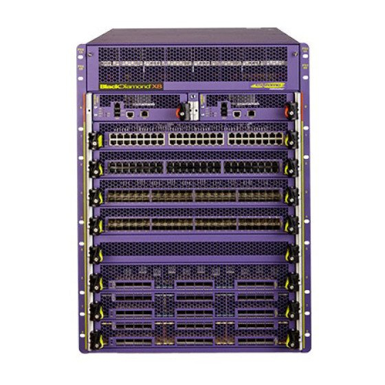
Figure 10: Front of the BlackDiamond 8810 chassis ESD wrist strap connector Fan tray I/O module slots MSM module slot I/O module slots Power supplies Power cord connectors ASP042 Figure 9 shows the rear panel of the BlackDiamond 8810 chassis. Extreme Networks Consolidated ExtremeXOS Hardware Installation Guide... -
Page 47: Blackdiamond 12804 Switch Chassis
One fan tray, accessed from the front right of the unit ● One connector for an ESD-preventive wrist strap ● Figure 12 shows a BlackDiamond 12804 chassis equipped with one MSM and three optional I/O modules. Extreme Networks Consolidated ExtremeXOS Hardware Installation Guide... - Page 48 The rear panel of the BlackDiamond 12804 chassis provides: Chassis serial number ● Ethernet MAC address of the switch ● Symbols of safety certification ● Access to the PSU/fan controllers ● Attachment point for optional chassis ground ● Extreme Networks Consolidated ExtremeXOS Hardware Installation Guide...
-
Page 49: Blackdiamond 12802 Switch Chassis
The bottom of the chassis has a label showing safety certification symbols and the Ethernet MAC address of the switch. The chassis serial number is on the side near the back of the chassis. Extreme Networks Consolidated ExtremeXOS Hardware Installation Guide... -
Page 50: Blackdiamond 10808 Switch
Figure 16 shows a BlackDiamond 10808 switch equipped with two MSM-1 modules and eight optional I/O modules. Extreme Networks Consolidated ExtremeXOS Hardware Installation Guide... - Page 51 BlackDiamond 10808 Switch Figure 16: Front view of the BlackDiamond 10808 switch MSM module I/O module slots slots I/O module slots ESD wrist strap connector Power supplies behind grill EX_001 Extreme Networks Consolidated ExtremeXOS Hardware Installation Guide...
- Page 52 Access to the fan units ● Chassis serial number ● Ethernet MAC address of the switch ● Symbols of safety certification ● Access to power supply controllers ● Attachment point for optional chassis ground ● Extreme Networks Consolidated ExtremeXOS Hardware Installation Guide...
-
Page 53: Chapter 3: Blackdiamond 8800 Modules
Do not attempt to mix and match modules across Extreme Networks product lines. BlackDiamond 8800 series modules are for use in a BlackDiamond 8800 series switch only, such as a BlackDiamond 8810 or BlackDiamond 8806 switch. When a BlackDiamond 8800 series switch is in use, ExtremeXOS software will not recognize a module from a different product line. -
Page 54: Msm Activity
BlackDiamond 8800 Modules MSM Activity The BlackDiamond 8800 series of switches can run with a single MSM installed. When you install an additional MSM, one of the MSMs operates as the primary MSM and the other becomes the backup (secondary) MSM. - Page 55 NOTE See the ExtremeXOS 12.0 Concepts Guide and the ExtremeXOS 12.0 Command Reference Guide for more information about numbering conventions for the modules and ports, as well as configuration and display information. Extreme Networks Consolidated ExtremeXOS Hardware Installation Guide...
-
Page 56: Msm Leds
No configuration information is stored on the I/O modules; all configuration information is stored on the MSM(s). When a BlackDiamond 8800 series switch is powered on, the software generates a default configuration for any slots that contain I/O modules. The default configuration allows the I/O module ports to... -
Page 57: Blackdiamond 8800 Original Series I/O Modules
When BlackDiamond 8800 I/O modules from different series (original series, a-series, and e-series) are installed in the same BlackDiamond 8800 series chassis, limitations on feature sets may occur. See the ExtremeXOS 12.0 Concepts Guide and the ExtremeXOS 12.0 Command Reference Guide for complete details regarding these limitations. -
Page 58: 10G4X I/O Module
The 10G4X I/O module has the following LEDs: Module status ● Module diagnostics ● Port status ● For information about the LEDs and their activity on the 10G4X I/O module, see “I/O Module LEDs” on page Extreme Networks Consolidated ExtremeXOS Hardware Installation Guide... -
Page 59: G48T I/O Module
For information about the LEDs and their activity on the G48T I/O module, see “I/O Module LEDs” on page G48P I/O Module Figure 23 shows the G48P I/O module. Figure 23: G48P I/O module 10/100/1000BASE-T PoE ports Module status LEDs ASP039A Extreme Networks Consolidated ExtremeXOS Hardware Installation Guide... - Page 60 The G48P I/O module has the following LEDs: Module status ● Module diagnostics ● Port status ● Power status ● For information about the LEDs and their activity on the G48P I/O module, see “I/O Module LEDs” on page Extreme Networks Consolidated ExtremeXOS Hardware Installation Guide...
-
Page 61: Blackdiamond 8800 A-Series I/O Modules
G48Ta I/O Module Figure 24 shows the G48Ta I/O module. Figure 24: G48Ta I/O module 10/100/1000BASE-T ports Module status LEDs ASP048 The G48Ta I/O module has 48 autosensing 10/100/1000BASE-T ports that use standard RJ-45 connectors. Extreme Networks Consolidated ExtremeXOS Hardware Installation Guide... -
Page 62: G48Xa I/O Module
The G48Xa module has the following LEDs: Module status ● Module diagnostics ● Port status ● For information about the LEDs and their activity on the G48Xa module, see “I/O Module LEDs” on page Extreme Networks Consolidated ExtremeXOS Hardware Installation Guide... -
Page 63: 10G4Xa I/O Module
The default configuration of the 10G4Ca I/O module is as follows. All ports: Are added to the default VLAN as untagged ● Inherit the properties of the default VLAN (for example, protocol type and VLANid) ● Extreme Networks Consolidated ExtremeXOS Hardware Installation Guide... -
Page 64: Blackdiamond 8800 E-Series I/O Modules
The default configuration of the G48Te I/O module is as follows. All ports: Are added to the default VLAN as untagged ● Inherit the properties of the default VLAN (for example, protocol type and VLANid) ● Operate in autonegotiation mode ● Extreme Networks Consolidated ExtremeXOS Hardware Installation Guide... -
Page 65: G48Pe I/O Module
The G48Pe I/O module has the following LEDs: Module status ● Module diagnostics ● Port/Power status ● For information about the LEDs and their activity on the G48Pe I/O module, see “I/O Module LEDs” on page Extreme Networks Consolidated ExtremeXOS Hardware Installation Guide... -
Page 66: I/O Module Leds
Amber Diagnostic failure Port LEDs on Non-PoE Modules This section describes the port LEDs for non-PoE BlackDiamond 8800 series I/O modules. These include the G24X, G48T, 10G4X, G48Ta, G48Xa, G48Te, 10G4Xa, and 10G4Ca I/O modules. Table 8 describes the LED meanings for each port on the non-PoE BlackDiamond 8800 series I/O modules. -
Page 67: Port Leds On Poe Modules (G48P And G48Pe)
I/O Modules Port LEDs on PoE Modules (G48P and G48Pe) The BlackDiamond 8800 series I/O modules that support PoE are the G48P and G48Pe modules. Port LEDs on these modules indicate the status of the inline power delivered through the ports. - Page 68 BlackDiamond 8800 Modules Extreme Networks Consolidated ExtremeXOS Hardware Installation Guide...
-
Page 69: Chapter 4: Blackdiamond 12800 Series Modules
GM-20T I/O module CAUTION Do not attempt to mix modules across Extreme Networks product lines. BlackDiamond 12800 series modules are for use only in a BlackDiamond 12802 or 12804 switch. When a BlackDiamond 12800 series switch is in use, ExtremeXOS software will not recognize a module from a different product line. -
Page 70: Blackdiamond 12800 Series Msms
Networks support website and follow the upgrade instructions in the ExtremeXOS 12.0 Release Notes. NOTE The MSM slot in the BlackDiamond 12802 switch is labeled MSM on the front panel. The ExtremeXOS software refers to this MSM as MSM-A in all related displays and command output. Extreme Networks Consolidated ExtremeXOS Hardware Installation Guide... -
Page 71: Redundant Msm Activity
Power-on self-test (POST) is running. Normal operation for diagnostics. Amber A critical software error has been logged since power-up. Normal operation. Green Environment (temperature, fan, power supply) is operating properly. Amber Environmental failure has occurred. Extreme Networks Consolidated ExtremeXOS Hardware Installation Guide... -
Page 72: Msm-5 And Msm-5R Modules
The MSM-5 module and MSM-5R module consist of a printed circuit board mounted on a metal panel that acts as the insertion vehicle in the BlackDiamond 12800 series switch. The module carrier also includes ejector/injector levers and captive retaining screws at each end of the module front panel. Extreme Networks Consolidated ExtremeXOS Hardware Installation Guide... -
Page 73: Blackdiamond 12800 Series I/O Modules
Compact flash—You can insert an external compact flash memory card into this slot. (See Chapter 2 ● for more information about Extreme Networks-supported compact flash cards.) Reset—Use the Reset button to reset the MSM without removing the module from the chassis. ●... -
Page 74: I/O Port Leds
GM-20T I/O Module Figure 32 shows the GM-20T I/O module. Figure 32: GM-20T I/O module Module status LEDs 10/100/1000BASE-T EX_152h The GM-20T I/O module has 20 autosensing 10/100/1000BASE-T ports that use standard RJ-45 connectors. Extreme Networks Consolidated ExtremeXOS Hardware Installation Guide... -
Page 75: Gm-20T Leds
The GM-20XTR is part of the R series and includes the rate limiting feature; the GM-20XT module does not support rate limiting. To use rate limiting, you must install the MSM-5R plus the GM-20XTR I/O module and/or the XM-2XR I/O module. Extreme Networks Consolidated ExtremeXOS Hardware Installation Guide... -
Page 76: Gm-20Xt And Gm-20Xtr Leds
The XM-2XR module is part of the R series and includes the rate limiting feature; the XM-2X module does not support rate limiting. To use rate limiting, you must install the MSM-5R plus the GM-20XTR I/O module and/or the XM-2XR I/O module. Extreme Networks Consolidated ExtremeXOS Hardware Installation Guide... -
Page 77: Xm-2X And Xm-2Xr Leds
The specific slot locations for I/O modules and MSMs in the chassis are as follows: BlackDiamond 12804 switch ● I/O modules in slots 1, 2, 5, and 6 ■ MSMs in slots 3/A and 4/B ■ Extreme Networks Consolidated ExtremeXOS Hardware Installation Guide... - Page 78 The MSM slot in the BlackDiamond 12802 switch is labeled MSM on the front panel. This slot will only operate an MSM. The ExtremeXOS software refers to this MSM as MSM-A in all related displays and command output. Extreme Networks Consolidated ExtremeXOS Hardware Installation Guide...
-
Page 79: Chapter 5: Blackdiamond 10808 Series Modules
MSMs are installed in designated lettered slots in the BlackDiamond 10808 system chassis. Figure 38 shows the front panel of the BlackDiamond 10808 series MSM. Figure 38: BlackDiamond 10808 series MSM Module status LEDs Module reset button Management port Console port Compact flash EX_003 Extreme Networks Consolidated ExtremeXOS Hardware Installation Guide... -
Page 80: Msm Activity
For example, in a BlackDiamond 10808 switch with a primary MSM in slot A and a backup MSM in slot B, if you remove the primary MSM from slot A, the backup MSM in slot B becomes the primary MSM. Extreme Networks Consolidated ExtremeXOS Hardware Installation Guide... -
Page 81: Msm Leds
To reset the critical software error LED (amber ERR LED), use the clear log static command and reboot the switch. If you continue to have critical software errors, or the ERR LED is amber after the clear log static command and a switch reboot, contact Extreme Networks Customer Support. Extreme Networks Consolidated ExtremeXOS Hardware Installation Guide... -
Page 82: About The Blackdiamond 10808 I/O Modules
If you preconfigure a slot for a specific module type, and then insert a different type of module, the module reverts to its default configuration. NOTE See the ExtremeXOS 12.0 Concepts Guide and the ExtremeXOS 12.0 Command Reference Guide for more information about configuring I/O modules. Extreme Networks Consolidated ExtremeXOS Hardware Installation Guide... -
Page 83: G60T Module
The G60T module has the following LEDs: Module status ● Port status ● Port speed ● For information about the LEDs and their activity on the G60T module, see “I/O Module LEDs” on page Extreme Networks Consolidated ExtremeXOS Hardware Installation Guide... -
Page 84: G60X Module
LX mini-GBIC, which conforms to the 1000BASE-LX standard ● ZX mini-GBIC, which conforms to the IEEE 802.3z standard ● NOTE For more information about the supported mini-GBIC types and specifications, see “Mini-GBIC Interfaces” on page 338. Extreme Networks Consolidated ExtremeXOS Hardware Installation Guide... -
Page 85: G60X Leds
The default configuration of the G20X module is as follows. All ports: Are added to the default VLAN as untagged ● Inherit the properties of the default VLAN (for example, protocol type and VLANid) ● Extreme Networks Consolidated ExtremeXOS Hardware Installation Guide... -
Page 86: Mini-Gbic Ports
“I/O Module LEDs” on page 10G6X Module Figure 42 shows the 10G6X module. Figure 42: 10G6X module Module status LEDs 10 Gbs ports EX_006 The 10G6X module has six unpopulated XENPAK-based 10 Gigabit Ethernet ports. Extreme Networks Consolidated ExtremeXOS Hardware Installation Guide... -
Page 87: Xenpak Ports
LX4 XENPAK ● LW XENPAK ● ● CX4 XENPAKs are also supported with Extreme Networks devices; contact your vendor to obtain these. NOTE For more information about the supported XENPAK types and specifications, see “XENPAK Interfaces” on page 354. 10G6X LEDs... -
Page 88: 10G2X Module
● LW XENPAK ● NOTE CX4 XENPAKs are also supported with Extreme Networks devices; contact your vendor to obtain these. For more information about the supported XENPAK types and specifications, see “XENPAK Interfaces” on page 354. Extreme Networks Consolidated ExtremeXOS Hardware Installation Guide... -
Page 89: 10G2X Leds
The default configuration of the 10G2H module is as follows. All ports: Are added to the default VLAN as untagged ● Inherit the properties of the default VLAN (for example, protocol type and VLANid) ● Extreme Networks Consolidated ExtremeXOS Hardware Installation Guide... -
Page 90: Xenpak Ports
LX4 XENPAK ● LW XENPAK ● NOTE CX4 XENPAKs are also supported with Extreme Networks devices; contact your vendor to obtain these. For more information about the supported XENPAK types and specifications, see “XENPAK Interfaces” on page 354. Mini-GBIC Ports... -
Page 91: I/O Module Leds
Configuration error, code version error, diagnostic failure, or other severe module error No power DIAG Normal operation Amber blinking Diagnostics in progress Amber Diagnostic failure Port x Green Link up Green blinking Link down Amber blinking Packet activity Link down Extreme Networks Consolidated ExtremeXOS Hardware Installation Guide... - Page 92 BlackDiamond 10808 Series Modules Extreme Networks Consolidated ExtremeXOS Hardware Installation Guide...
-
Page 93: Part 3: Installing Blackdiamond Switches And Modules
Installing BlackDiamond Switches and Modules... -
Page 95: Chapter 6: Installing The Blackdiamond 8810 Chassis
WARNING! Correct lifting procedures for the BlackDiamond 8810 chassis require two or more people. Only trained service personnel should perform service to Extreme Networks switches and their components. Trained service personnel have read all related installation manuals, have the technical training and experience necessary to be aware of the hazards to which they are exposed in performing a task, and are aware of measures to minimize the danger to themselves or other persons. -
Page 96: Unpacking The Blackdiamond 8810 Chassis
Do not proceed with uncrating and unpacking the chassis if either the Tilt Indicator or the Shock Indicator is displaying a red warning state. Immediately contact Extreme Networks if a red condition occurs. 2 Open the flaps and remove the contents from the upper BlackDiamond 8810 shipping carton (see Figure 46). - Page 97 4 Lift the BlackDiamond 8810 shipping carton up and off the chassis. 5 Remove all four restraining bolts that hold the BlackDiamond 8810 chassis to the four shipping brackets on the shipping pallet (see Figure 48). Extreme Networks Consolidated ExtremeXOS Hardware Installation Guide...
- Page 98 The BlackDiamond 8810 chassis should be empty before being lifted. This will also prevent damage to the system components due to possible chassis flex when lifting. 7 Carefully lift the BlackDiamond 8810 chassis off the shipping pallet and onto the floor as shown in Figure Extreme Networks Consolidated ExtremeXOS Hardware Installation Guide...
-
Page 99: Pre-Installation Requirements
NOTE Save all packaging, bolts, washers, and clip locks, as well as the box and pallet for future use in the event that the chassis needs to be moved to another location or returned to Extreme Networks. Pre-Installation Requirements The following tools and equipment are required for installing the BlackDiamond 8810 chassis: ESD-preventive wrist strap (provided) ●... -
Page 100: Attaching The Blackdiamond 8810 Mid-Mount Rack Brackets
4 On each side of the chassis, attach the appropriate mid-mount bracket using the eight mounting screws provided in the kit (see Figure 50). Figure 50: Mid-mount brackets attached to the BlackDiamond 8810 chassis Mid-Mount Bracket ASP034 Extreme Networks Consolidated ExtremeXOS Hardware Installation Guide... -
Page 101: Rack Mounting The Blackdiamond 8810 Chassis
Figure 51: Attaching the helper bracket to the system rack EX_086A 4 Lift the back of the empty chassis onto the helper bracket. 5 Slowly guide the chassis into the system rack until the mounting brackets are flush against the rack uprights. Extreme Networks Consolidated ExtremeXOS Hardware Installation Guide... - Page 102 Figure 52: Securing the BlackDiamond 8810 chassis to a standard rack system EX_172A 7 Remove the helper bracket from the system rack after the chassis is secured. Save the bracket for future use if you remove the chassis from the rack. Extreme Networks Consolidated ExtremeXOS Hardware Installation Guide...
-
Page 103: Grounding The Blackdiamond 8810 Chassis
2 Strip 0.5-inch (1.2-cm) of insulation from the stranded copper wire cable. 3 Insert the stripped wire into the cable lug. CAUTION Be sure that no copper is visible between the lug and the cable insulation. Extreme Networks Consolidated ExtremeXOS Hardware Installation Guide... -
Page 104: Initial Management Access
6 Connect the other end of the wire to a known reliable earth ground point at your site. Initial Management Access For instructions on accessing the switch for initial management setup, see Chapter 2, “Initial Management Access.” Extreme Networks Consolidated ExtremeXOS Hardware Installation Guide... -
Page 105: Chapter 7: Installing The Blackdiamond 8806 And Blackdiamond 12804 Chassis
Correct lifting of the BlackDiamond 8806/12804 chassis requires two or more people. WARNING! The BlackDiamond 8806/12804 chassis should be empty before being lifted. This will also prevent damage to the system components due to possible system chassis flex when lifting. Extreme Networks Consolidated ExtremeXOS Hardware Installation Guide... -
Page 106: Unpacking The Blackdiamond 8806/12804 Chassis
Squeeze the prongs inward, applying equal pressure on each side. c Pull the prongs outward until the clip lock is released from the carton. Repeat steps 2a through 2c to release each of the remaining clip locks. Extreme Networks Consolidated ExtremeXOS Hardware Installation Guide... - Page 107 4 Slide the shipping carton up over the BlackDiamond 8806/12804 chassis (see Figure 56). Figure 56: Removing the carton from the BlackDiamond 8806/12804 chassis Lift box chassis Open & remove 4 clip locks to free box EX_120A 5 Unwrap the chassis. Extreme Networks Consolidated ExtremeXOS Hardware Installation Guide...
- Page 108 ● NOTE Save all packaging, clip locks, and box for future use in the event that the BlackDiamond 8806/12804 chassis needs to be moved to another location or returned to Extreme Networks, Inc. Extreme Networks Consolidated ExtremeXOS Hardware Installation Guide...
-
Page 109: Pre-Installation Requirements
Each mid-mount bracket is clearly marked for placement on either the right or left side, as viewed from the front of the chassis. 4 On each side of the chassis, attach the appropriate mid-mount bracket using the eight screws provided in the kit (see Figure 58). Extreme Networks Consolidated ExtremeXOS Hardware Installation Guide... -
Page 110: Rack-Mounting The Blackdiamond 8806/12804 Chassis
2 Identify the rack location where the chassis will be installed. 3 Using four rack mounting screws, attach the helper bracket to the system rack immediately below the chassis location (see Figure 59). You must provide the screws for attaching the helper bracket. Extreme Networks Consolidated ExtremeXOS Hardware Installation Guide... - Page 111 NOTE Figure 60 shows a standard rack mount. For mid-mount installation, use the same mounting locations shown in the figure, but insert the screws through the designated slot locations of the mid-mount brackets. Extreme Networks Consolidated ExtremeXOS Hardware Installation Guide...
-
Page 112: Grounding The Blackdiamond 8806/12804 Chassis
For AC systems using a 20A breaker per PSU (SSI AC), the chassis ground can be as small as ■ 14 AWG. For DC systems using a 40A breaker per PSU (SSI DC), the chassis ground can be as small as ■ 10 AWG. Extreme Networks Consolidated ExtremeXOS Hardware Installation Guide... -
Page 113: Initial Management Access
6 Connect the other end of the wire to a known reliable earth ground point at your site. Initial Management Access For instructions on accessing the switch for initial management setup, see Chapter 2, “Initial Management Access.” Extreme Networks Consolidated ExtremeXOS Hardware Installation Guide... - Page 114 Installing the BlackDiamond 8806 and BlackDiamond 12804 Chassis Extreme Networks Consolidated ExtremeXOS Hardware Installation Guide...
-
Page 115: Chapter 8: Installing The Blackdiamond 12802 Chassis
Figure 62). 3 Remove the packing foam on top of the chassis (see Figure 62). 4 At the side of the chassis, remove the package of mounting brackets and hardware (see Figure 62). Extreme Networks Consolidated ExtremeXOS Hardware Installation Guide... - Page 116 6 Break the inspection seal on the packing bag and remove the chassis from the bag. NOTE Save the box and all packaging for future use in case the BlackDiamond 12802 chassis must be returned to Extreme Networks, Inc. Extreme Networks Consolidated ExtremeXOS Hardware Installation Guide...
-
Page 117: Rack-Mounting The Blackdiamond 12802 Chassis
2 Insert and tighten the provided flat-head screws to secure the brackets to the chassis. Figure 63: Mounting flanges at the front Bracket Screw Bracket BD_147 3 Slide the chassis into the system rack. Extreme Networks Consolidated ExtremeXOS Hardware Installation Guide... -
Page 118: Mid-Mounting A Blackdiamond 12802 Chassis
3 Slide the chassis into the equipment rack. 4 Attach the chassis to the system rack using eight rack system mounting screws (screws not provided). Refer to Figure 66 for the screw locations. Extreme Networks Consolidated ExtremeXOS Hardware Installation Guide... -
Page 119: Grounding The Blackdiamond 12802 Chassis
For AC systems using a 20A breaker per PSU (SSI AC), the chassis ground can be as small as ■ 14 AWG. For DC systems using a 40A breaker per PSU (SSI DC), the chassis ground can be as small as ■ 10 AWG. Extreme Networks Consolidated ExtremeXOS Hardware Installation Guide... -
Page 120: Initial Management Access
6 Connect the other end of the wire to a known reliable earth ground point at your site. Initial Management Access For instructions on accessing the switch for initial management setup, see Chapter 2, “Initial Management Access.” Extreme Networks Consolidated ExtremeXOS Hardware Installation Guide... -
Page 121: Chapter 9: Installing A Blackdiamond 10808 Chassis
CAUTION Correct lifting procedures for the BlackDiamond 10808 chassis requires two or more people. Only trained service personnel should perform service to Extreme Networks switches and their components. Trained service personnel have read all related installation manuals, have the technical training and experience necessary to be aware of the hazards to which they are exposed in performing a task, and are aware of measures to minimize the danger to themselves or other persons. -
Page 122: Required Tools And Resources
Checking the Shipping Status Indicators Before you begin unpacking the chassis from the carton, locate the tilt watch and shock watch shipping status indicators on the side of the shipping carton (Figure 68). Extreme Networks Consolidated ExtremeXOS Hardware Installation Guide... - Page 123 Each indicator has two color-coded states, or modes: a good, white state, and a warning, red state. A smooth shipping procedure should leave all four indicators in good, white states. Figure 69 shows the tilt watch and shock watch indicators in both conditions. Extreme Networks Consolidated ExtremeXOS Hardware Installation Guide...
-
Page 124: Removing The Accessories Box
CAUTION If either the tilt watch or shock watch indicator is showing a red warning condition, do not proceed with unpacking. Contact your shipping company or Extreme Networks and speak to a representative before continuing. Removing the Accessories Box Begin unpacking the chassis from the carton by removing the accessories box from the top of the carton. - Page 125 4 Set the accessories box aside in a safe place. The accessories box contains: 19-inch helper bracket for installing the chassis in a rack ● ESD-preventive wrist strap ● Front bezel for shielding the switch after installation ● Documentation and media ● Extreme Networks Consolidated ExtremeXOS Hardware Installation Guide...
-
Page 126: Removing The Carton From The Chassis
V-boards EX_093A 2 Remove the four detachable plastic clip locks found near the bottom of the shipping carton, as shown in Figure Two clip locks are located on each side of the carton. Extreme Networks Consolidated ExtremeXOS Hardware Installation Guide... - Page 127 Repeat steps 2a through 2c to release each of the remaining three clip locks. Figure 73: Removing the clip locks Squeeze prongs to unlock Clip lock Open lock EX_087B 3 Slide the carton up over the chassis, as shown in Figure Extreme Networks Consolidated ExtremeXOS Hardware Installation Guide...
-
Page 128: Installing The Chassis
The BlackDiamond 10808 switch is shipped with a pre-installed fan tray. For your safety, because of the increased weight of the chassis after components are installed and to prevent damage to the equipment, Extreme Networks strongly recommends that you install the I/O modules after you mount the chassis in a rack. -
Page 129: Standard Rack Installation
2 Mount the helper bracket in the lowest available position in the rack using four appropriate screws (not provided), as shown in Figure Figure 75: Helper bracket for mounting the BlackDiamond 10808 switch EX_086A 3 Using all four handles, lift the switch from the pallet, as shown in Figure Extreme Networks Consolidated ExtremeXOS Hardware Installation Guide... - Page 130 5 Using the higher handles at the front, slowly guide the chassis into the rack until it is securely seated. 6 While holding the empty chassis, secure the chassis to the rack, using eight rack-mount screws (see Figure 77). Extreme Networks Consolidated ExtremeXOS Hardware Installation Guide...
- Page 131 Figure 77: Securing the BlackDiamond 10808 chassis to a standard rack EX_009A 7 After you secure the chassis to the rack, remove the helper bracket. Store the bracket for future use; for example, if you need to remove the chassis from the rack. Extreme Networks Consolidated ExtremeXOS Hardware Installation Guide...
-
Page 132: Mid-Mount Rack Installation
Figure 78: Helper bracket for mounting the BlackDiamond 10808 switch EX_086A 3 Attach a mid-mount flange to each side of the BlackDiamond 10808 chassis using the provided screws. Use the appropriate flange for the left and right side, as shown in Figure Extreme Networks Consolidated ExtremeXOS Hardware Installation Guide... - Page 133 Installing the Chassis Figure 79: Mid-mount flange for the BlackDiamond 10808 chassis Midmount flanges EX_075 Extreme Networks Consolidated ExtremeXOS Hardware Installation Guide...
-
Page 134: Grounding The Blackdiamond 10808 Chassis
For AC systems using a 20A breaker per PSU (SSI AC), the chassis ground can be as small as ■ 14 AWG. For DC systems using a 40A breaker per PSU (SSI DC), the chassis ground can be as small as ■ 10 AWG. Extreme Networks Consolidated ExtremeXOS Hardware Installation Guide... - Page 135 5 Insert the screws through the lug and into the grounding point on the back of the chassis. 6 Connect the other end of the wire to a known reliable earth ground point at your site. Extreme Networks Consolidated ExtremeXOS Hardware Installation Guide...
-
Page 136: Initial Management Access
Installing a BlackDiamond 10808 Chassis Initial Management Access For instructions on accessing the switch for initial management setup, see Chapter 2, “Initial Management Access.” Extreme Networks Consolidated ExtremeXOS Hardware Installation Guide... -
Page 137: Chapter 10: Extreme Networks Power Supply Units For Blackdiamond Switches
National Electrical Code. CAUTION Building codes vary worldwide; therefore, Extreme Networks strongly recommends that you consult an electrical contractor to ensure proper equipment grounding and power distribution for your specific installation. -
Page 138: Blackdiamond Psu Compatibility
WARNING! Field operators must not attempt to open the PSU enclosure for any reason; the PSU does not contain user-serviceable parts. In the event of failure, return the defective PSU to Extreme Networks for repair or replacement. BlackDiamond PSU Compatibility The BlackDiamond power supply units are intended for use in specific BlackDiamond switches only. -
Page 139: Extreme Networks 1200 W Dc Psu
Field operators must not attempt to open the 1200 W DC PSU enclosure for any reason; the PSU does not contain user-serviceable parts. In the event of failure, return the defective 1200 W DC PSU to Extreme Networks for repair or replacement. -
Page 140: Pre-Installation Requirements
Extreme Networks Power Supply Units for BlackDiamond Switches Pre-Installation Requirements You need the following tools and equipment to install or remove a 1200 W DC PSU: ESD preventive wrist strap ● Input DC power cable (provided with the DC PSU) ●... -
Page 141: Installing An Extreme Networks 1200 W Dc Psu
Extreme Networks 1200 W DC PSU Installing an Extreme Networks 1200 W DC PSU To install an Extreme Networks 1200 W DC PSU: 1 Attach an ESD-preventive wrist strap to your wrist and connect the metal end to the ground receptacle, which is located on the top-left corner of the switch front panel. - Page 142 Extreme Networks Power Supply Units for BlackDiamond Switches 3 Carefully slide the 1200 W DC PSU all the way into the power supply bay (see Figure 84). Be sure that the DC PSU is fully seated in the switch. CAUTION Do not slam the 1200 W DC PSU into the system switch backplane.
- Page 143 To install additional 1200 W DC PSUs, repeat steps 2 through 6. NOTE Leave the ESD strap permanently connected to the switch, so that the strap is always available when you need to handle ESD-sensitive components. Extreme Networks Consolidated ExtremeXOS Hardware Installation Guide...
-
Page 144: Removing An Extreme Networks 1200 W Dc Psu
The DC PSU may be hot to the touch; use thermal protective gloves when handling the 1200 W DC PSU during removal. To remove an Extreme Networks 1200 W DC PSU: 1 Attach an ESD-preventive wrist strap to your bare wrist and connect the metal end to the ground receptacle on the top-left corner of the switch front panel (if not already attached). -
Page 145: Front Panel Leds
The front panel of the 1200 W DC PSU provides status LEDs. Table 18 identifies the symbols and describes the LED behavior. Table 18: Extreme Networks 1200 W DC PSU front panel LED behavior Power Predictive Fail Fail PSU Condition... -
Page 146: Extreme Networks 700/1200 W Ac Psu
WARNING! Extreme Networks 700/1200 W AC PSUs do not have switches for turning the unit on and off. Remove the wall plug from the electrical outlet to disconnect the power to an Extreme Networks 700/1200 W AC PSU. Make sure that this connection is always easily accessible. -
Page 147: Installing An Extreme Networks 700/1200 W Ac Psu
1 Attach an ESD-preventive wrist strap to your wrist and connect the metal end to the ground receptacle, which is located on the top-left corner of the switch front panel. 2 Verify that the Extreme Networks 700/1200 W AC PSU is right side up and the locking handle is open (see Figure 87). - Page 148 88). CAUTION Do not slam the Extreme Networks 700/1200 W AC PSU into the system switch backplane. Use the locking handle to secure the Extreme Networks 700/1200 W AC PSU into the system switch. Figure 88: Extreme Networks 700/1200 W AC PSU sliding into the power supply bay...
-
Page 149: Removing An Extreme Networks 700/1200 W Ac Psu
3 Lift the handle up on the Extreme Networks 700/1200 W AC PSU. 4 Pull on the handle of the Extreme Networks 700/1200 W AC PSU to remove it from the power supply bay. 5 Place both hands underneath the Extreme Networks 700/1200 W AC PSU to support the weight after it is pulled out from the switch. -
Page 150: Front Panel Leds
No input power to any PSU Power supply failure The front panel on each Extreme Networks 700/1200 W AC PSU contains two cooling fans as shown in Figure 87. Airflow enters from the front vents on the Extreme Networks 700/1200 W AC PSU and exits to the rear vents of the switch. -
Page 151: Fuse
Extreme Networks 700/1200 W AC PSU for a complete replacement. WARNING! Field operators must not attempt to configure or replace fuses in Extreme Networks 700/1200 W AC PSUs! In the event of failure, immediately return the defective Extreme Networks 700/1200 W AC PSU for a complete replacement. -
Page 152: Extreme Networks 600/900 W Ac Psu
CAUTION To ensure proper cooling of the PSU, do not block the front vents of the Extreme Networks 600/900 W AC PSU or the rear vents of the switch. Figure 89: Extreme Networks 600/900 W AC PSU... -
Page 153: Minimum Software Required
WARNING! Extreme Networks 600/900 W AC PSUs do not have switches for turning the unit on and off. Remove the wall plug from the electrical outlet to disconnect the power to an Extreme Networks 600/900 W AC PSU. Make sure that this connection is easily accessible. -
Page 154: Installing An Extreme Networks 600/900 W Ac Psu
91). CAUTION Do not slam the Extreme Networks 600/900 W AC PSU into the system switch backplane. Use the locking handle to secure the Extreme Networks 600/900 W AC PSU into the system switch. Figure 91: Inserting a 600/900 W AC PSU into the power supply bay... -
Page 155: Removing Or Replacing An Extreme Networks 600/900 W Ac Psu
3 Lift the handle up on the Extreme Networks 600/900 W AC PSU. 4 Pull on the handle of the Extreme Networks 600/900 W AC PSU to disconnect it from the power connector at the back of the power supply bay. -
Page 156: Front Panel Leds
Power Supply Cords Extreme Networks 600/900 W AC PSU(s) are shipped with both 110 V AC and 220 V AC power supply cords. The 110 V AC power supply cord allows for a maximum DC output power of 600 W. The 220V AC power supply cord allows for a maximum DC output power of 900 W. -
Page 157: Fuse
Extreme Networks 600/900 W AC PSU for a complete replacement. WARNING! Field operators must not attempt to configure or replace fuses in Extreme Networks 600/900 W AC PSUs! In the event of failure, immediately return the defective Extreme Networks 600/900 W AC PSU for a complete replacement. -
Page 158: Extreme Networks 325 W Dc Power Supply
The Extreme Networks 325 W DC PSU cannot be used in conjunction with any other Extreme Networks PSU. The 325 W DC PSU should be connected to a DC power source using the Extreme Networks DC power input cable Model # 65025. This cable is shipped separately from the power supply. -
Page 159: Pre-Installation Requirements
WARNING! Extreme Networks 325 W DC PSUs do not have switches for turning the unit on and off. Make sure that the DC circuit is de-energized before connecting or disconnecting the DC power cord and socket on the Extreme Networks 325 W DC PSU. -
Page 160: Installing An Extreme Networks 325 W Dc Psu
Provide proper connection and strain relief on the DC power cord in accordance with all local and national electrical codes. CAUTION Make sure that the Extreme Networks 325 W DC PSU circuit is not overloaded. Use proper over-current protection, such as a circuit breaker, to prevent over-current conditions. NOTE A minimum of two Extreme Networks 325 W DC PSUs are required to run a BlackDiamond 12802 switch. - Page 161 (If this bay is empty, a cover plate is required.) NOTE A minimum of two Extreme Networks 325 W DC PSUs are required to run a BlackDiamond 12802 switch. WARNING! Do not put your hand into an open power supply bay when a power supply is not present. Empty power supply bays require a cover plate at all times.
- Page 162 Extreme Networks Power Supply Units for BlackDiamond Switches Figure 94: Installing the Extreme Networks 325 W DC PSU Chassis DC OU DC IN DC PSU Torino DC PSU_01A 4 To secure the 325 W DC PSU in the power supply bay, align and tightening the two captive screws on the PSU front panel.
-
Page 163: Removing An Extreme Networks 325 W Dc Psu
To disconnect system power, disconnect ALL power supply units. Disconnect the power cord before you remove the PSU from the chassis. To remove an Extreme Networks 325 W DC PSU: 1 Turn off the DC power at the source. 2 Attach an ESD-preventive wrist strap to your wrist and connect the metal end to the ground receptacle on the top right corner of the switch front panel. -
Page 164: Leds
Green Green Fuse The Extreme Networks 325 W DC PSU line is fused. This fuse is not replaceable in the field. In the event of failure, immediately return the Extreme Networks 325 W DC PSU for a complete replacement. WARNING! Field operators must not attempt to configure or replace fuses inside Extreme Networks 325 W DC PSUs! In the event of failure, immediately return the defective Extreme Networks 325 W DC PSU for a complete replacement. -
Page 165: Extreme Networks 325 W Ac Power Supply
WARNING! Extreme Networks 325 W AC PSUs do not have switches for turning the unit on and off. Remove the wall plug from the electrical outlet to disconnect the power to an Extreme Networks 325 W AC PSU. Make sure that this connection is easily accessible. -
Page 166: Installing An Extreme Networks 325 W Ac Psu
Figure 97: Extreme Networks 325 W AC PSU 325W AC PSU Torino AC PSU_04 3 Carefully slide the Extreme Networks 325 W AC PSU all the way into an open power supply bay (see Figure 98) until you hear a click. - Page 167 Extreme Networks 325 W AC Power Supply CAUTION Do not slam the Extreme Networks 325 W AC PSU into the system backplane. CAUTION To prevent an electrical hazard, make sure before you install the PSU in the power supply bay that the AC power cord is not connected to the PSU.
-
Page 168: Installing Retaining Brackets And Connecting Power
Extreme Networks Power Supply Units for BlackDiamond Switches Installing Retaining Brackets and Connecting Power A power cord retaining bracket is shipped with each 325 W AC PSU. These brackets hold the power connectors in the power sockets and prevent accidental disconnection due to earthquakes, vibration, or other disturbances. - Page 169 Extreme Networks 325 W AC Power Supply Figure 101: Power cord brackets on two adjacent power supplies Torino AC PSU_09 2 Connect the AC power cord to the PSU as follows: a Connect the AC power cord to the AC input on the front of the PSU (see Figure 102).
-
Page 170: Removing An Extreme Networks 325 W Ac Psu
Leave the ESD strap permanently connected to the switch, so that the strap is always available when you need to handle ESD-sensitive components. Front Panel LEDs The front panel of the Extreme Networks 325 W AC PSU provides status LEDs. Table 20 describes the meanings of these LEDs. -
Page 171: Power Supply Cords
Extreme Networks 325 W AC PSU for a complete replacement. WARNING! Field operators must not attempt to configure or replace fuses in Extreme Networks 325 W AC PSUs! In the event of failure, immediately return the defective Extreme Networks 325 W AC PSU for a complete replacement. - Page 172 Extreme Networks Power Supply Units for BlackDiamond Switches Extreme Networks Consolidated ExtremeXOS Hardware Installation Guide...
-
Page 173: Chapter 11: Installing Blackdiamond Series Modules
CAUTION Do not attempt to mix modules across Extreme Networks product lines. BlackDiamond 8800 series modules are for use only in a BlackDiamond 8810 or 8806 switch. Blackdiamond 12800 series modules are for use only in a BlackDiamond 12804 or 12802 switch. When a BlackDiamond switch is in use, ExtremeXOS software will not recognize a module from a different product line. -
Page 174: Distinguishing A Blackdiamond 8800 Or 12800 Msm From An I/O Module
Orange injector/ejector release latches indicate that the module is a BlackDiamond MSM, and green injector/ejector release latches indicate that the module is a BlackDiamond I/O module (see Figure 103). Extreme Networks Consolidated ExtremeXOS Hardware Installation Guide... -
Page 175: Installing A Blackdiamond 8800 Or 12800 Series Module
CAUTION The module series number must be the same as the switch series number. For example, install BlackDiamond 8800 modules only in a BlackDiamond 8800 series switch. To install a module in a BlackDiamond 8800 or 12800 series switch: 1 Attach the ESD-preventive wrist strap to your wrist and connect the metal end to the ground receptacle on the chassis. - Page 176 Figure 105: Injector/ejector handles shown in the latched position EX_124 CAUTION There are two styles of ejector/injector handles on the BlackDiamond 8800 and 12800 series modules. Pay careful attention to the instructions in the next step. Extreme Networks Consolidated ExtremeXOS Hardware Installation Guide...
- Page 177 9 Store the module packaging for future use. NOTE Leave the ESD-preventive wrist strap permanently connected to the chassis so that the strap is always available when you need to handle ESD-sensitive components. Extreme Networks Consolidated ExtremeXOS Hardware Installation Guide...
-
Page 178: Connecting And Disconnecting Cables On The 10G4Ca Module
3 Evenly push the latch toward the module port to secure the connection (Figure 108). Make sure that the latch engages equally on both sides. Figure 108: Connecting a 10G4Ca module port BD_157 Extreme Networks Consolidated ExtremeXOS Hardware Installation Guide... -
Page 179: Installing A Blackdiamond 10808 Series Module
You need the following tools and equipment to install a module ESD-preventive wrist strap (provided) ● # 2 Phillips screwdriver ● Appropriate type of cable for the module if you are installing an I/O module ● Extreme Networks Consolidated ExtremeXOS Hardware Installation Guide... - Page 180 To prevent ESD damage, handle the module by the metal panel edges only. Never touch the components on the printed circuit board or the pins on any of the connectors. 6 Extend the injector/ejector levers and hold the module vertically with the module name at the top (see Figure 110). Extreme Networks Consolidated ExtremeXOS Hardware Installation Guide...
- Page 181 To install additional modules, repeat steps through 9. NOTE Leave the ESD-preventive wrist strap permanently connected to the chassis so that it is always available when you need to handle ESD-sensitive components. Extreme Networks Consolidated ExtremeXOS Hardware Installation Guide...
-
Page 182: Installing A Backup Msm
For more information about slot status information, see the ExtremeXOS 12.0 Concepts Guide and the ExtremeXOS 12.0 Command Reference Guide. Extreme Networks Consolidated ExtremeXOS Hardware Installation Guide... -
Page 183: Removing A Blackdiamond 8800 Or 12800 Series Module
Be sure to turn each captive screw only 90 degrees or one-quarter turn counter-clockwise. Loosening the captive screws beyond 90 degrees will damage the injector/ejector handles on the module. Figure 111: Unlocking a module EX_125a Extreme Networks Consolidated ExtremeXOS Hardware Installation Guide... -
Page 184: Removing A Blackdiamond 10808 Series Module
2 At each end of the module front panel, loosen the retaining screws with a #1 Phillips screwdriver. 3 Simultaneously rotate the ejector/injector levers outward to disengage the module from the backplane. Extreme Networks Consolidated ExtremeXOS Hardware Installation Guide... -
Page 185: Blackdiamond Series Blank Front Panels
Figure 113). On a BlackDiamond 8800 series or 12800 series chassis, make sure that the EMI gasket is on the top of the panel and the stenciled part number is right side up. On a BlackDiamond 10808 chassis, position the blank front panel with the EMI gasket to the right. -
Page 186: Removing A Blank Front Panel
On a BlackDiamond 12802 chassis, the ground receptacle is at the top right corner. 2 Loosen the captive screw at each end of the blank front panel, using a #2 Phillips screwdriver (see Figure 114). Extreme Networks Consolidated ExtremeXOS Hardware Installation Guide... - Page 187 3 Remove the blank front panel from the intended slot on the BlackDiamond switch (see Figure 115). Figure 115: Blank front panel being removed from a BlackDiamond 8800 series or 12800 series switch ASP020 4 Install an I/O module or MSM in the open slot as described in “Installing a BlackDiamond 8800 or...
-
Page 188: Installing Or Removing An External Compact Flash Memory Card
2 Locate the compact flash slot on the MSM, as shown in Figure 116. Figure 116: Typical compact flash slot location (BlackDiamond 8800 series MSM) Console port Compact flash ASP038B 3 Hold the memory card between your thumb and forefinger. -
Page 189: Part 4: Installing Blackdiamond Switch Accessories
Installing BlackDiamond Switch Accessories... -
Page 191: Chapter 12: Blackdiamond Ac Power Cord Retaining Brackets
The AC power cord retaining brackets for BlackDiamond switches hold the power connectors in the power sockets and prevent accidental disconnection due to earthquakes, vibration, or other disturbances. Power cord retaining brackets are provided with the BlackDiamond 8800 series switches and the 12800 series switches. - Page 192 5 Align the BlackDiamond 8810 AC power cord retaining bracket over the AC power cord ends as shown in Figure 120. Figure 120: AC power cord retaining bracket correctly aligned REMOVE TO INSTALL POWER CORDS ASP012A Extreme Networks Consolidated ExtremeXOS Hardware Installation Guide...
-
Page 193: Disconnecting A Blackdiamond 8810 Ac Power Cord
5 Remove the end of the AC power cord from the power outlet(s) on the front of the switch. NOTE Leave the ESD-preventive wrist strap permanently connected to the switch so that it is always available when you need to touch ESD-sensitive components. Extreme Networks Consolidated ExtremeXOS Hardware Installation Guide... -
Page 194: Blackdiamond 8806/12804 Ac Power Cord Retainer Channel
Verify that all installed AC power cords are firmly plugged into the power connectors. Figure 122: Installing and routing the AC power cords Starting at the left, insert each plug and lift power cord over previous plug EX_138 Extreme Networks Consolidated ExtremeXOS Hardware Installation Guide... - Page 195 5 Starting from the left, lay the first four power cords into the channel (see Figure 125). 6 Lay the last two power cords on top of the bottom four cords (see Figure 125). Extreme Networks Consolidated ExtremeXOS Hardware Installation Guide...
-
Page 196: Removing The Blackdiamond 8806/12804 Ac Power Cord Retainer Channel
3 Remove the retainer channel from the switch. NOTE Leave the ESD-preventive wrist strap permanently connected to the switch, so that the strap is always available when you need to handle ESD-sensitive components. Extreme Networks Consolidated ExtremeXOS Hardware Installation Guide... -
Page 197: Chapter 13: Blackdiamond Cable Management
Six rack-mounting screws appropriate for your organization’s rack system ● Screwdriver suitable for the rack-mounting screws ● The BlackDiamond cable manager consists three parts: the mounting base, the cable guides, and a cover (see Figure 126). Extreme Networks Consolidated ExtremeXOS Hardware Installation Guide... - Page 198 1 At the top of the cover, lift the latches as you pull out on the corners to open the cover. 2 Rotate the cover outward and lift it off the base. Removing the cover exposes the six screws holding the cable guides onto the mounting base (see Figure 127). Extreme Networks Consolidated ExtremeXOS Hardware Installation Guide...
- Page 199 Insert the remaining screws. c Tighten all six screws securely. Be sure that the screws do not protrude from the cable manager mounting base and prevent the cable guides from fitting properly over the base. Extreme Networks Consolidated ExtremeXOS Hardware Installation Guide...
- Page 200 6 Reattach the cable guides to the cable manager mounting base using the screws you removed previously (see Figure 129). Do not overtighten the screws. Figure 129: Securing the cable guides to the mounted cable manager base EX_077 Extreme Networks Consolidated ExtremeXOS Hardware Installation Guide...
- Page 201 Use the cable holders and cable clips to organize and bundle the cables, as described in “Using the Cable Holders and Cable Clips” on page 202. Figure 130: Using the cable manager EX_080A Extreme Networks Consolidated ExtremeXOS Hardware Installation Guide...
-
Page 202: Using The Cable Holders And Cable Clips
Top view of open/removed cover EX_078 Using the Cable Holders and Cable Clips When you use the cable holders and the cable clips, Extreme Networks recommends the following: Attach the cables to the holders by slipping the cable through the opening. ●... -
Page 203: Connecting Cable Holders
1 Hold two cable holders as shown in Figure 133. Make sure that one locking tab at the joint is on top and the other is on the bottom. Figure 133: Connecting cable holders ENIN003 Extreme Networks Consolidated ExtremeXOS Hardware Installation Guide... -
Page 204: Connecting Cable Clips
1 Hold two clips next to each other with the split sides facing the same way (see Figure 135). 2 Slide the connecting grooves together (see Figure 135). Figure 135: Connecting cable clips ENIN001A Extreme Networks Consolidated ExtremeXOS Hardware Installation Guide... - Page 205 ENIN002A 4 Connect as many cable clips together as you need to manage your cable bundles. 5 To disconnect the cable clips, push on the bottom ring while holding the top ring steady. Extreme Networks Consolidated ExtremeXOS Hardware Installation Guide...
- Page 206 BlackDiamond Cable Management Extreme Networks Consolidated ExtremeXOS Hardware Installation Guide...
-
Page 207: Part 5: Blackdiamond Maintenance Procedures
BlackDiamond Maintenance Procedures... -
Page 209: Chapter 14: Replacing The Blackdiamond 12802 Psu/Fan Controller And Fan Tray
Removing the fan tray for more than a few minutes may result in overheating and possible damage to the system. Thermal sensors shut down power if the internal temperature exceeds 60 °C. Make sure you have the replacement unit before starting this procedure. Extreme Networks Consolidated ExtremeXOS Hardware Installation Guide... - Page 210 Align the fan tray with the fan tray slot on the switch, and then slide the fan tray into place in the switch (see Figure 138). CAUTION Use both hands to support the weight of the fan tray during installation. Extreme Networks Consolidated ExtremeXOS Hardware Installation Guide...
-
Page 211: Replacing A Blackdiamond Psu/Fan Controller
Using a #2 Phillips screwdriver, turn the captive retaining screws counter-clockwise to loosen them completely. b Use the handle to pull the controller out of the BlackDiamond 12802 chassis (Figure 139). Set the controller on an ESD-preventive surface. Extreme Networks Consolidated ExtremeXOS Hardware Installation Guide... - Page 212 PSU/fan controller module BD_148 5 Power on the switch. NOTE Leave the ESD-preventive wrist strap permanently connected to the switch so that it will always be available when you need to handle ESD-sensitive components. Extreme Networks Consolidated ExtremeXOS Hardware Installation Guide...
-
Page 213: Chapter 15: Replacing A Blackdiamond 8800 Series/Blackdiamond 12804 Psu/Fan Controller
Each of these BlackDiamond switches contains two PSU/fan controllers that collect and report data from the Extreme Networks AC power supply units and the BlackDiamond fan tray. The BlackDiamond 8800/12804 PSU/fan controllers intervene in the event of power inconsistencies and provide primary/backup redundancy should a BlackDiamond 8800/12804 PSU/fan controller fail. - Page 214 Replacing a BlackDiamond 8800 Series/BlackDiamond 12804 PSU/Fan Controller To remove a BlackDiamond 8800/12804 PSU/fan controller from the BlackDiamond 8800/12804 switch: 1 Attach the ESD-preventive wrist strap to your wrist and connect the metal end to the ground receptacle that is located on the front top-left corner of the switch.
- Page 215 7 Pull the PSU/fan controller out from the PSU control card access panel on the switch, by pulling equally on the upper and lower handles. Leave the ESD-preventive wrist strap permanently connected to the switch, so that the strap is always available when you need to handle ESD-sensitive components. Extreme Networks Consolidated ExtremeXOS Hardware Installation Guide...
-
Page 216: Installing A Blackdiamond 8800/12804 Spare Psu/Fan Controller
Replacing a BlackDiamond 8800 Series/BlackDiamond 12804 PSU/Fan Controller Installing a BlackDiamond 8800/12804 Spare PSU/Fan Controller NOTE Beginning with ExtremeXOS version 11.2.1.3, you can hot swap the PSU/fan controller unit. Refer to the ExtremeXOS 12.0 Concepts Guide for complete information on upgrading software. -
Page 217: Chapter 16: Replacing A Blackdiamond 12804 Or 8800 Series Fan Tray
2 Locate the captive screws at the top and bottom of the fan tray. 3 Using a #2 Phillips screwdriver, turn each captive screw counter-clockwise to loosen the screws as shown in Figure 143 Figure 144. Extreme Networks Consolidated ExtremeXOS Hardware Installation Guide... - Page 218 Be sure that all fan blade motion has ceased before continuing to remove the fan tray. 5 Support the bottom of the fan tray with your free hand as you use the handle to slide the fan tray completely out from the fan tray slot. Extreme Networks Consolidated ExtremeXOS Hardware Installation Guide...
-
Page 219: Installing The Blackdiamond 8810 Spare Fan Tray
Be sure that both hands are used to support the weight of the fan tray during installation. Figure 145: Installing the fan tray in the BlackDiamond 8810 switch Fan Tray Captive Screws (x2) Fan Tray Handle ASP030A Extreme Networks Consolidated ExtremeXOS Hardware Installation Guide... - Page 220 3 Use a #2 Phillips screwdriver to turn each captive screw clockwise to tighten the screws (Figure 145). Leave the ESD-preventive wrist strap permanently connected to the switch so that it is always available when you need to touch ESD-sensitive components. Extreme Networks Consolidated ExtremeXOS Hardware Installation Guide...
-
Page 221: Chapter 17: Replacing The Blackdiamond 10808 Switch Fan Tray, Air Filter, And Power Supply Controller
2 Unscrew the two captive screws that secure the fan tray to the chassis 3 Use the finger grips to pull the fan tray out of the chassis approximately 1 inch (2.54 cm); this step disconnects the power and causes the fans to stop rotating. Extreme Networks Consolidated ExtremeXOS Hardware Installation Guide... -
Page 222: Installing The Replacement Fan Tray
4 Tighten the captive retaining screws to secure the fan tray to the chassis. Leave the ESD-preventive wrist strap permanently connected to the chassis so that it is always available when you need to handle ESD-sensitive components. Extreme Networks Consolidated ExtremeXOS Hardware Installation Guide... -
Page 223: Replacing The Blackdiamond 10808 Air Filter
Replacement filter ● NOTE Extreme Networks recommends that you visually inspect the air filter at least once every three months. Replace or clean as necessary. To replace the filter in the BlackDiamond 10808 switch: 1 Remove the bezel from the front of the chassis using a #2 Phillips screwdriver. -
Page 224: Replacing The Blackdiamond 10808 Power Supply Controller
The RJ-45 port on the power supply controller is not an Ethernet port and no connection should be made to it. The front panel of the power supply controller has status LEDs. Table 26 describes the LED behavior on the power supply controller. Extreme Networks Consolidated ExtremeXOS Hardware Installation Guide... -
Page 225: Pre-Installation Requirements
2 If a blank faceplate is covering the power supply controller bay, remove it and save it for future use. 3 Using a #2 Phillips screwdriver, loosen the captive retaining screws on the power supply controller. 4 Remove the power supply controller from the slot. Extreme Networks Consolidated ExtremeXOS Hardware Installation Guide... -
Page 226: Installing A Power Supply Controller
● If the switch passes the POST, the MGMT LED blinks at a slow rate (one blink per second). If the switch fails the POST, the MGMT LED shows a solid yellow light. Extreme Networks Consolidated ExtremeXOS Hardware Installation Guide... -
Page 227: Chapter 18: Repacking A Blackdiamond Chassis
Repacking a BlackDiamond Chassis This chapter describes how to remove a BlackDiamond chassis from an equipment rack and repack the chassis for shipping back to Extreme Networks. To repack a BlackDiamond chassis, use the original shipping crate or box and packing materials. -
Page 228: Repacking The Blackdiamond 8810 Chassis
Repacking the BlackDiamond 8810 Chassis To repack the BlackDiamond 8810 chassis: 1 Remove all modules and power supplies from the chassis. Follow correct Extreme Networks procedures for removing components. 2 Using four mounting screws, attach the helper bracket to the system rack immediately below the chassis. - Page 229 Repeat steps 8a through 8c to insert each of the remaining clip locks. Figure 152: Clip locks located on BlackDiamond 8810 shipping carton Squeeze prongs to unlock Clip lock Open lock EX_087B Extreme Networks Consolidated ExtremeXOS Hardware Installation Guide...
- Page 230 11 Close the top flaps on the shipping carton and seal them with packing tape. 12 Secure the BlackDiamond 8810 shipping carton with nylon straps as shown in Figure 154. Figure 154: BlackDiamond 8810 shipping carton with nylon straps ASP026 Extreme Networks Consolidated ExtremeXOS Hardware Installation Guide...
-
Page 231: Repacking The Blackdiamond 8806/12804 Chassis
6 Carefully lift the chassis off the helper bracket and lower it onto the foam cushion in the shipping carton base (see Figure 155.) Figure 155: Setting the BlackDiamond 8806/12804 chassis onto the foam cushion EX_129 Extreme Networks Consolidated ExtremeXOS Hardware Installation Guide... - Page 232 Proper installation of the clip locks is critical for safe shipment of the BlackDiamond 8806/12804 chassis. Make sure that the clip locks are secure and accurately installed. Figure 157: Clip locks on the BlackDiamond 8806/12804 chassis shipping carton Squeeze prongs to unlock Clip lock Open lock EX_111A Extreme Networks Consolidated ExtremeXOS Hardware Installation Guide...
- Page 233 159). NOTE Nylon straps are optional but are recommended by Extreme Networks for extra security during shipment. The installation of nylon straps requires a crimping tool. If you do not have nylon straps and a crimping tool available to secure the carton, the chassis can be shipped without the straps; however, it is critical that the clip locks be secure before shipment.
-
Page 234: Repacking The Blackdiamond 12802 Chassis
1 Prepare the shipping box. Remove saved packing materials except the lower foam cushion, which should be in the bottom of the box. 2 Remove all modules and power supplies from the chassis. Follow correct Extreme Networks procedures for removing components from the BlackDiamond chassis. -
Page 235: Repacking The Blackdiamond 10808 Chassis
Repacking the BlackDiamond 10808 Chassis Repacking the BlackDiamond 10808 Chassis To repack the BlackDiamond 10808 chassis for return to Extreme Networks, you must recrate it using the original packaging materials. NOTE Contact Extreme Networks Customer Support for instructions on returning the chassis. - Page 236 5 Engage the four plastic clip locks near the bottom of the shipping carton (see Figure 163). Two clip locks are located on opposite sides of the carton. Figure 163: Location of clip locks Cardboard box Clip locks Pallet EX_182 Extreme Networks Consolidated ExtremeXOS Hardware Installation Guide...
- Page 237 Figure 164: Installing the clip locks Squeeze prongs to unlock Clip lock Close lock EX_087C 6 Insert the four v-boards in the corners of the crate (see Figure 165). Figure 165: Inserting the v-boards Accessory box EX_093 Extreme Networks Consolidated ExtremeXOS Hardware Installation Guide...
- Page 238 166. Figure 166: Nylon strap location Corner protectors Nylon straps Pallet EX_094 CAUTION Do not overtighten the nylon straps. Tighten them securely, but not enough to crush the corners of the shipping crate. Extreme Networks Consolidated ExtremeXOS Hardware Installation Guide...
-
Page 239: Part 6: Summit Family Of Switches
Summit Family of Switches... -
Page 241: Chapter 19: Summit Family Of Switches
Refer to the following sections for specific hardware details about each series: Summit X250e Series Switches on page 242 ● Summit X450 Series Switches on page 252 ● Summit X450a Series Switches on page 256 ● Summit X450e Series Switches on page 270 ● Extreme Networks Consolidated ExtremeXOS Hardware Installation Guide... -
Page 242: Summit X250E Series Switches
If one power supply fails, the other power supply will provide sufficient power to operate the switch. Summit X250e-24t Switch Front Panel Figure 167 shows the front panel of the Summit X250e-24t switch. Extreme Networks Consolidated ExtremeXOS Hardware Installation Guide... -
Page 243: Summit X250E-24T Switch Rear Panel
Used to connect an Ethernet cable directly from a laptop into the management port to view and ■ locally manage the switch configurations. Two LEDs for the management port, located in the bottom corners of the port. ● Extreme Networks Consolidated ExtremeXOS Hardware Installation Guide... -
Page 244: Summit X250E-24P Switch
Stack number indicator—Numeric indicator of the position of this switch in a stacked configuration. ● 10/100BASE-T PoE ports—Twenty-four 10/100BASE-T PoE ports that deliver high-density copper ● connectivity and a full 15.4 Watts of PoE per port Extreme Networks Consolidated ExtremeXOS Hardware Installation Guide... -
Page 245: Summit X250E-24P Switch Rear Panel
Forty-eight fixed 10/100BASE-T ports (ports 1–48) that deliver high-density copper connectivity for ● 4.8 Gbps Two combination ports (ports 49–50) that provide 10/100/1000 BASE-T or mini-GBIC connectivity ● for 2 Gbps of copper or fiber connectivity Extreme Networks Consolidated ExtremeXOS Hardware Installation Guide... -
Page 246: Summit X250E-48T Switch Front Panel
2 Gbps of copper or fiber connectivity. Console port—Serial port used to connect a terminal and perform local management. ● Summit X250e-48t Switch Rear Panel Figure 172 shows the rear panel of the Summit X250e-48t switch. Extreme Networks Consolidated ExtremeXOS Hardware Installation Guide... -
Page 247: Summit X250E-48P Switch
(Model No. 10913) installed in an EPS-C chassis (Model No. 10912). The PoE capability of the Summit X250e-48p switch varies depending on the number of external power modules in use. For complete details, see “EPS-600LS External Power Module” on page 328. Extreme Networks Consolidated ExtremeXOS Hardware Installation Guide... -
Page 248: Summit X250E-48P Switch Front Panel
Summit X250e-48p Switch Rear Panel Figure 174 shows the rear panel of the Summit X250e-48p switch. Figure 174: Summit X250e-48p switch rear panel External power Management port supply connection 10 Gigabit Power socket stacking ports SH_043 Extreme Networks Consolidated ExtremeXOS Hardware Installation Guide... -
Page 249: Summit X250E-48P Power Supplies
The PoE capability of the Summit X250e-48p varies depending on the number of external power modules in use. Table 28 summarizes the PoE power behavior for the Summit X250e-48p switch based on the number of power supply modules in use. Extreme Networks Consolidated ExtremeXOS Hardware Installation Guide... -
Page 250: Summit X250E Series Switch Leds
No power Power LEDs PSU-I Steady green Normal operation (Internal power supply) Blinking amber Failure No power PSU-E Steady green Normal operation (External power supply) Blinking amber Failure No external power attached Extreme Networks Consolidated ExtremeXOS Hardware Installation Guide... - Page 251 Steady green Link OK Stack Port 1, Stack Port 2 Blinking green Activity (rear panel) No link Other LEDs Management Port Right LED: Link OK (rear panel) Steady green Left LED: Activity Blinking green Extreme Networks Consolidated ExtremeXOS Hardware Installation Guide...
-
Page 252: Summit X450 Series Switches
Summit X450-24t switch. Figure 175: Summit X450-24t switch front panel Console Mini-GBIC ports 10/100/1000 Mbps ports port Band On = Link Blinking = Activity STACK NO. Shared Ports Stack number indicator Shared ports S450_002C Extreme Networks Consolidated ExtremeXOS Hardware Installation Guide... -
Page 253: Summit X450-24T Switch Rear Panel
The connecting redundant power supply cable is shipped with the EPS-160. AC power socket ● The switch automatically adjusts to the supply voltage. The power supply operates from 100 VAC to 240 VAC. Extreme Networks Consolidated ExtremeXOS Hardware Installation Guide... -
Page 254: Summit X450-24X Switch
Stack number indicator—Numeric indicator of the position of this switch in a stacked configuration. ● Combination ports—Four combination ports that provide 10/100/1000 BASE-T or mini-GBIC ● connectivity for 4 Gbps of fiber or copper connectivity. Extreme Networks Consolidated ExtremeXOS Hardware Installation Guide... -
Page 255: Summit X450-24X Switch Rear Panel
The connecting redundant power supply cable is shipped with the EPS-160. AC power socket ● The switch automatically adjusts to the supply voltage. The power supply operates from 100 VAC to 240 VAC. Extreme Networks Consolidated ExtremeXOS Hardware Installation Guide... -
Page 256: Summit X450A Series Switches
Summit X450a-24t switch. When this switch is used with the EPS-LD, the power supplies (internal and redundant) are fully fault tolerant and load-sharing. If one power supply fails, the other power supply will provide sufficient power to operate the switch. Extreme Networks Consolidated ExtremeXOS Hardware Installation Guide... -
Page 257: Summit X450A-24T Switch Front Panel
Summit X450a-24t switch. Figure 180: Summit X450a-24t switch rear panel External power Management port supply connection 10 Gigabit 10 Gigabit Power socket uplink option stacking ports SH_028 Extreme Networks Consolidated ExtremeXOS Hardware Installation Guide... - Page 258 The connecting redundant power supply cable is shipped with the EPS-LD. AC power socket ● The switch automatically adjusts to the supply voltage. The power supply operates from 100 VAC to 240 VAC. Extreme Networks Consolidated ExtremeXOS Hardware Installation Guide...
-
Page 259: Summit X450A-24Tdc Switch
Summit X450a-24tDC switch. Figure 181: Summit X450-24tDC switch front panel Console 10/100/1000 Mbps ports port Solid ON=Link Blinking=Activity MGMT STACK NO. Stack PSU-1 PSU-E Shared Ports Stack number indicator Shared ports SH_020A Extreme Networks Consolidated ExtremeXOS Hardware Installation Guide... -
Page 260: Summit X450A-24Tdc Switch Rear Panel
Used to connect an Ethernet cable directly from your laptop into the management port to view ■ and locally manage the switch configurations. Two LEDs for the management port, located at the bottom corners of the port. ● Two high-performance stacking ports ● Extreme Networks Consolidated ExtremeXOS Hardware Installation Guide... -
Page 261: Summit X450A-24X Switch
Summit X450a-24x switch. Figure 183: Summit X450a-24x switch front panel Shared ports Solid ON = Link Blinking = Activity MGMT STACK NO. Stack PSU-1 PSU-E Stack number Console indicator port 1000BASE-X ports SH_033A Extreme Networks Consolidated ExtremeXOS Hardware Installation Guide... -
Page 262: Summit X450A-24X Switch Rear Panel
Used to connect an Ethernet cable directly from your laptop into the management port to view ■ and locally manage the switch configurations. Two LEDs for the management port, located in the bottom corners of the port. ● Two high-performance stacking ports ● Extreme Networks Consolidated ExtremeXOS Hardware Installation Guide... -
Page 263: Summit X450A-24Xdc Switch
For centralized DC power connection, this product is intended to be installed in Restricted Access Locations (Dedicated Equipment Rooms, Equipment Closets, or the like) in accordance with Articles 110-16, 110-17, and 110-18 of the National Electric Code, ANSI/NFPA 70. Extreme Networks Consolidated ExtremeXOS Hardware Installation Guide... -
Page 264: Summit X450A-24Xdc Switch Front Panel
Summit XGM2-2xn option card, which allows you to add up to two 10 Gigabit XENPAK modules ■ Summit XGM2-2xf option card, which allows you to add up to two 10 Gigabit XFP modules ■ Extreme Networks Consolidated ExtremeXOS Hardware Installation Guide... -
Page 265: Summit X450A-48T Switch
Summit X450a-48t switch. When this switch is used with the EPS-500, the power supplies (internal and redundant) are fully fault tolerant and load-sharing. If one power supply fails, the other power supply will provide sufficient power to operate the switch. Extreme Networks Consolidated ExtremeXOS Hardware Installation Guide... -
Page 266: Summit X450A-48T Switch Front Panel
Summit XGM2-2xn option card, which allows you to add up to two 10 Gigabit XENPAK modules ■ Summit XGM2-2xf option card, which allows you to add up to two 10 Gigabit XFP modules ■ Extreme Networks Consolidated ExtremeXOS Hardware Installation Guide... -
Page 267: Summit X450A-48Tdc Switch
Summit X450a-48tDC switch. When this switch is used with the EPS-150DC, the power supplies (internal and redundant) are fully fault tolerant and load-sharing. If one power supply fails, the other power supply will provide sufficient power to operate the switch. Extreme Networks Consolidated ExtremeXOS Hardware Installation Guide... -
Page 268: Summit X450A-48Tdc Switch Front Panel
4 Gbps of copper or fiber connectivity. 10/100/1000 BASE-T Ethernet ports—Forty-four 10/100/1000 BASE-T Ethernet ports that deliver ● high-density copper connectivity in 1.75-inch (1U) form factor. Console port—Serial port used to connect a terminal and perform local management. ● Extreme Networks Consolidated ExtremeXOS Hardware Installation Guide... -
Page 269: Summit X450A-48Tdc Switch Rear Panel
The connecting redundant power supply cable is shipped with the EPS-500. AC power socket ● The switch automatically adjusts to the supply voltage. The power supply operates from 100 VAC to 240 VAC. Extreme Networks Consolidated ExtremeXOS Hardware Installation Guide... -
Page 270: Summit X450E Series Switches
Summit X450e-24p switch. When this switch is used with the EPS-LD, the power supplies (internal and redundant) are fully fault tolerant and load-sharing. If one power supply fails, the other power supply will provide sufficient power to operate the switch. Extreme Networks Consolidated ExtremeXOS Hardware Installation Guide... -
Page 271: Summit X450E-24P Switch Front Panel
Summit X450e-24p switch. Figure 192: Summit X450e-24p switch rear panel External power Management port supply connection 10 Gigabit 10 Gigabit Power socket uplink option stacking ports SH_027 Extreme Networks Consolidated ExtremeXOS Hardware Installation Guide... -
Page 272: Summit X450E-48P Switch
Summit XGM2-2xn option card, which allows you to add up to two 10 Gigabit XENPAK modules ■ Summit XGM2-2xf option card, which allows you to add up to two 10 Gigabit XFP modules ■ Extreme Networks Consolidated ExtremeXOS Hardware Installation Guide... -
Page 273: Summit X450E-48P Switch Front Panel
10/100/1000 BASE-T PoE ports—Forty-four 10/100/1000 BASE-T PoE ports that deliver high- ● density copper connectivity and a full 15.4 Watts of PoE per port Console port—Serial port used to connect a terminal and perform local management. ● Extreme Networks Consolidated ExtremeXOS Hardware Installation Guide... -
Page 274: Summit X450E-48P Switch Rear Panel
328. The connecting redundant power supply cable is shipped with the EPS-C chassis. AC power socket ● The switch automatically adjusts to the supply voltage. The power supply operates from 100 VAC to 240 VAC. Extreme Networks Consolidated ExtremeXOS Hardware Installation Guide... -
Page 275: Summit X450E-48P Power Supplies
740 W of 740 W of No PoE power Power Failure external power only external power only external power only with 2:1 redundancy For complete details, see “EPS-600LS External Power Module” on page 328. Extreme Networks Consolidated ExtremeXOS Hardware Installation Guide... -
Page 276: Summit X450, X450A, And X450E Series Switch Leds
Stacking Port LED Green Solid Link OK Green Blinking Activity SFP 1G Port LED Green Solid Link OK Green Blinking Activity XENPAK 10G Port LED Green Solid Link OK Green Blinking Activity Link down Extreme Networks Consolidated ExtremeXOS Hardware Installation Guide... - Page 277 Port is powered with link, no traffic Blinking Amber Port is powered with link, traffic Slow Blinking Port is powered, with no link Amber Alternating Amber Port is faulted and Green Port is not powered, no link or disabled Extreme Networks Consolidated ExtremeXOS Hardware Installation Guide...
- Page 278 Summit Family of Switches Extreme Networks Consolidated ExtremeXOS Hardware Installation Guide...
-
Page 279: Chapter 20: Installing Summit Family Switches
Read the information in this chapter thoroughly before you attempt to install or remove a Summit switch. Safety Information Only trained service personnel should perform service to Extreme Networks switches and their components. Trained service personnel have read all related installation manuals, have the technical training and experience necessary to be aware of the hazards to which they are exposed in performing a task, and are aware of measures to minimize the danger to themselves or other persons. -
Page 280: Building A Summitstack Configuration
Stack Port 2 Stack Port 1 Stack Port 2 Stack Port 1 Stack Port 2 BD_165C The stacking cables are available from Extreme Networks. Table 32 lists the stacking cables available at this time. Table 32: Available SummitStack stacking cables Part Number... -
Page 281: About Redundancy
Connect Stack Port 2 on one switch to Stack Port 1 on the switch with the next higher slot number. Extreme Networks Consolidated ExtremeXOS Hardware Installation Guide... - Page 282 Slot 5 Port 2 Slot 7 Port 1 Slot 6 Port 2 Slot 8 Port 1 Slot 7 Port 2 Slot 1 Port 1 Figure 196: SummitStack cable connections using eight Summit switches BD_159B Extreme Networks Consolidated ExtremeXOS Hardware Installation Guide...
-
Page 283: Connecting A Stacking Cable To A Stacking Port
2 Firmly press the cable connector into place on the mating stacking port connector. 3 Align and tighten the retaining screws on the cable connector. Repeat steps through to connect the cable to the second switch. Extreme Networks Consolidated ExtremeXOS Hardware Installation Guide... -
Page 284: Connecting The Console Port
Stacking Port LEDs Each stacking port has an LED. The LED is solid green if the link is OK, blinking green if traffic is present, and off if there is no signal. Extreme Networks Consolidated ExtremeXOS Hardware Installation Guide... -
Page 285: Installing A Summit Family Switch
3 Insert the screws and fully tighten with a suitable screwdriver, as shown in Figure 199. Figure 199: Attaching the mounting bracket S450_007 4 Repeat steps for the other side of the switch. Extreme Networks Consolidated ExtremeXOS Hardware Installation Guide... -
Page 286: Free-Standing And Desktop Mounting Of Multiple Switches
For centralized DC power connection, these products are intended to be installed in Restricted Access Locations (Dedicated Equipment Rooms, Equipment Closets, or the like) in accordance with Articles 110-16, 110-17, and 110-18 of the National Electric Code, ANSI/NFPA 70. Extreme Networks Consolidated ExtremeXOS Hardware Installation Guide... -
Page 287: Connecting The Internal Dc Power Supply To The Dc Source Voltage
Phillips screwdriver appropriate to the provided screw ● Additional hardware appropriate to the earth ground connection at your site ● WARNING! Be sure to connect the chassis ground wire before you connect any power cables. Extreme Networks Consolidated ExtremeXOS Hardware Installation Guide... -
Page 288: Connecting The Dc Wiring Harness To The Dc Source Voltage
DC power connections at the rear of the switch. CAUTION The DC wiring harness must be properly connected to a DC main circuit breaker rated no greater than 20 A. Extreme Networks Consolidated ExtremeXOS Hardware Installation Guide... - Page 289 Table 35 provides the wire-to-pin connection specifications. Table 35: Wire-to-Pin Connection Specifications Number Wire Color Circuit Connection Green/Yellow Chassis Ground Return Black -48 V unused Extreme Networks Consolidated ExtremeXOS Hardware Installation Guide...
-
Page 290: Attaching The Dc Wiring Harness To The Dc Power Socket On The Switch
The pins must align properly for the cable to completely connect. Do not force the cable into the socket until the keyway is aligned properly. Refer to Figure 201 for the DC wiring harness connector. Extreme Networks Consolidated ExtremeXOS Hardware Installation Guide... -
Page 291: Removing A Summit X450A-48Tdc Switch From A Rack
6 Carefully remove the switch from the rack and place it on a secure, flat surface. WARNING! Removing the DC wiring harness from your facilities DC source voltage requires the performance of a qualified, licensed electrician. Extreme Networks Consolidated ExtremeXOS Hardware Installation Guide... -
Page 292: Initial Management Access
Installing Summit Family Switches Initial Management Access For instructions on accessing the switch for initial management setup, see Chapter 2, “Initial Management Access.” Extreme Networks Consolidated ExtremeXOS Hardware Installation Guide... -
Page 293: Chapter 21: Summit Option Cards
Disconnect power to the switch before installing or removing a Summit option card. After the Summit option card is installed in a compatible switch, compatible optical modules may be hot-swapped into and out of the option card. Use optics approved by Extreme Networks only. Three types of Summit option cards are available: Summit XGM-2xn option card: allows you to add up to two 10-gigabit XENPAK optical transceivers ●... -
Page 294: Safety Information
● NOTE Extreme Networks optics are tested to work in all supported Extreme Networks switches. We recommend that all customers use Extreme Networks optics in their Extreme Networks switches. Extreme Networks assumes no liability for third-party optics. While Extreme Networks does not block third-party optics, we cannot ensure that all third-party party optics operate properly in all Extreme Networks switches. -
Page 295: Summit Xgm-2Xn Option Card
Table 37, for the switch to discover the ZR XENPAK correctly. Table 37: Summit X450 ZR XENPAK combinations Left Slot Right Slot ZR XENPAK Empty ZR XENPAK SR XENPAK Extreme Networks Consolidated ExtremeXOS Hardware Installation Guide... -
Page 296: Installing The Summit Xgm-2Xn Option Card
4 Align the sheet metal edges on the option card with the card guides in the switch housing. Carefully slide the Summit XGM-2xn option card into the switch housing until the connectors engage and the card is flush with the back panel of the switch (Figure 204). Extreme Networks Consolidated ExtremeXOS Hardware Installation Guide... -
Page 297: Summit Xgm2-2Xn Option Card
Summit X450a-24xDC switch, running ExtremeXOS 11.6.1 (or later) ● Summit X450a-48t switch, running ExtremeXOS 11.5.0 (or later) ● Summit X450e-24p switch, running ExtremeXOS 11.5.0 (or later) ● Summit X450e-48p switch, running ExtremeXOS 11.6.1 (or later) ● Extreme Networks Consolidated ExtremeXOS Hardware Installation Guide... -
Page 298: Installing The Summit Xgm2-2Xn Option Card
CAUTION Be sure that the option slot always has either an installed Summit option card or a faceplate over the opening. An open slot could divert air from the switch and cause overheating. Extreme Networks Consolidated ExtremeXOS Hardware Installation Guide... - Page 299 XENPAK modules in the Summit XGM2-2xn option card. NOTE If you install only one XENPAK module in the Summit XGM2-2xn option card, attach the supplied cover plate over the remaining open module slot. Extreme Networks Consolidated ExtremeXOS Hardware Installation Guide...
-
Page 300: Installing Or Removing Xenpak Modules
4 Lift the handle on the Summit XGM-2xn or XGM2-2xn option card to allow the module to be inserted. 5 Hold the module by its sides and insert it into one of the slots on the Summit option card (Figure 209). Extreme Networks Consolidated ExtremeXOS Hardware Installation Guide... -
Page 301: Removing A Xenpak Module
1 Attach an ESD-preventive wrist strap to your wrist and connect the metal end to the equipment rack. 2 Disconnect the fiber-optic cable from the XENPAK module and install dust covers over the module connectors. Extreme Networks Consolidated ExtremeXOS Hardware Installation Guide... -
Page 302: Summit Xgm2-2Xf Option Card
The Summit XGM2-2xf option card is compatible with the following 10-gigabit XFP modules: LR XFP module ● SR XFP module ● Figure 210 shows the Summit XGM2-2xf option card. Figure 210: Summit XGM2-2xf option card SH_011 Extreme Networks Consolidated ExtremeXOS Hardware Installation Guide... -
Page 303: Installing The Summit Xgm2-2Xf Option Card
5 Align the sheet metal edges on the option card with the card guides in the switch housing. Carefully slide the Summit XGM2-2xf option card into the switch housing until the connectors engage and the option card is flush with the back panel of the switch (Figure 212). Extreme Networks Consolidated ExtremeXOS Hardware Installation Guide... -
Page 304: Installing Or Removing Xfp Modules
Installing or Removing XFP Modules This section describes installing and removing an XFP module. You can install or remove an XFP module from your Extreme Networks switch without powering off the system. Figure 213 shows a typical XFP module. -
Page 305: Installing An Xfp Module
6 Push the XFP handle (bail latch) upward until it clicks into place (see Figure 215). 7 Slide the XFP module as far into the slot as possible, until you hear it click, indicating that it is firmly attached (see Figure 215 Figure 216). Extreme Networks Consolidated ExtremeXOS Hardware Installation Guide... -
Page 306: Removing An Xfp Module
3 Carefully pull the XFP module out of the port. 4 Place the dust covers back into the XFP module connectors. 5 Place the XFP module immediately into an antistatic container to protect it from ESD damage and dust. Extreme Networks Consolidated ExtremeXOS Hardware Installation Guide... -
Page 307: Chapter 22: Summit External Power Supplies (Eps)
EPS-150DC External Power Module with EPS-T2 EPS-150DC: 10909 EPS-T2: 10910 Summit X450a-24x EPS-LD External Power Supply Unit 45019 Summit X450a-24xDC EPS-150DC External Power Module with EPS-T2 EPS-150DC: 10909 EPS-T2: 10910 Summit X450a-48t EPS-500 External Power Supply Unit 10911 Extreme Networks Consolidated ExtremeXOS Hardware Installation Guide... -
Page 308: Safety
EPS-C: 10912 Safety Only trained service personnel should perform service to Extreme Networks switches and their components. Trained service personnel have read all related installation manuals, have the technical training and experience necessary to be aware of the hazards to which they are exposed in performing a task, and are aware of measures to minimize the danger to themselves or other persons. -
Page 309: External Power Module (With Eps-T)
EPS-160 External Power Module (with EPS-T) EPS-160 External Power Module (with EPS-T) The Extreme Networks EPS-160 External Power Module can be added as a redundant power supply to the Summit X450-24t, X450-24x, X250e-24t, or X250e-48t switch. The entire EPS system consists of a tray (EPS-T) that holds one or two EPS-160 power supplies. -
Page 310: Installing An Eps-160 External Power Module
2 Remove the mounting bracket kit (including screws) from the packaging. 3 Locate a mounting bracket over the mounting holes on one side of the unit. 4 Insert the screws and fully tighten with a screwdriver, as shown in Figure 219. Extreme Networks Consolidated ExtremeXOS Hardware Installation Guide... -
Page 311: Installing An Eps-160 Into An Eps-T
1 Connect the keyed-end of the redundant power supply cord to the EPS-160 power supply (see Figure 220). The key is a plastic tab on the cord connector housing that fits into the chassis to ensure correct alignment of the connector. Extreme Networks Consolidated ExtremeXOS Hardware Installation Guide... -
Page 312: Removing An Eps-160 From An Eps-T
1 Disconnect the AC power by removing the plug from the wall. 2 Disconnect the AC power cord from the EPS-160 power supply. 3 Remove the redundant power cord from the EPS-160 supply. Extreme Networks Consolidated ExtremeXOS Hardware Installation Guide... -
Page 313: Eps-Ld External Power Supply Unit
EPS-T. EPS-LD External Power Supply Unit The Extreme Networks EPS-LD External Power Supply Unit can be added as a redundant power supply to the Summit X450a-24t or Summit X450e-24p switch. When attached to the Summit X450e-24p, the EPS-LD provides 465 W total power with 375 W dedicated for PoE applications. -
Page 314: Connecting The Eps-Ld To The Switch
One end of the EPS-LD cord has a keyed connector to ensure correct alignment of the connector (Figure 222). The key is a plastic tab on the cord connector housing that fits into the EPS-LD unit. Extreme Networks Consolidated ExtremeXOS Hardware Installation Guide... - Page 315 Figure 223: Connecting an EPS-LD unit to a switch Keyed end of redundant power cable Slot for key EPS-LD To AC Extreme switch Redundant power cable To AC Collin's ES4K021A XM 053 Extreme Networks Consolidated ExtremeXOS Hardware Installation Guide...
-
Page 316: Connecting The Eps-Ld To Power
2 Disconnect the AC power cord from the EPS-LD unit. 3 Disconnect the cord between the Extreme switch and the EPS-LD unit. 4 Remove the screws from the EPS-LD mounting brackets. 5 Slide the EPS-LD unit out of the rack. Extreme Networks Consolidated ExtremeXOS Hardware Installation Guide... -
Page 317: External Power Supply Unit
EPS-500 External Power Supply Unit EPS-500 External Power Supply Unit The Extreme Networks EPS-500 (External Power Supply Unit 10911) provides additional power to compatible Power over Ethernet (PoE) switches and other Extreme switches. The EPS-500 power supply provides up to 500 W of total power and up to 375 W of power dedicated to PoE applications. -
Page 318: Installing And Removing An Eps-500
You can mount the EPS-500 facing either the front or the back of the rack. For this reason, each unit has two sets of mounting holes on each side. Extreme Networks recommends that you mount the EPS-500 unit so that the power output connectors of the EPS-500 unit are on the same side as the external connector on the connecting switch. -
Page 319: Connecting The Eps-500
EPS-500 External Power Supply Unit NOTE Extreme Networks recommends that you mount the EPS-500 so that the output connectors are on the same side as the external connector on the connecting switch. If you mount the EPS-500 with the connectors facing in the opposite direction as the Extreme switch connector, leave at least 1 u between the switch and the EPS-500 through which to slide the power cords. - Page 320 LED status for the power supply. Table 41: LED status for EPS-500 Power LED Power LED Indicates Green, solid The external power supply is operating normally. The external power supply is not connected. Extreme Networks Consolidated ExtremeXOS Hardware Installation Guide...
-
Page 321: Removing An Eps-500 Unit
18 of the National Electric Code, ANSI/NFPA 70. Installing an EPS-T2 This section describes the installation process for the Extreme Networks EPS-T2 (External Power Supply Tray 10910). The EPS-T2 is a tray that holds one or two compatible external power supplies. -
Page 322: Pre-Installation Requirements
Always be sure that the DC circuit is de-energized before connecting or disconnecting the DC wiring harness at the DC power socket on the rear of the EPS-150DC unit, and before connecting or disconnecting the redundant power cord between the switch and the EPS-150DC unit. Extreme Networks Consolidated ExtremeXOS Hardware Installation Guide... -
Page 323: Connecting The Dc Wiring Harness To The Dc Source Voltage
The DC wiring harness must be properly connected to a DC main circuit breaker or fuse rated no greater than 20 A. CAUTION Provide proper connection and strain relief on the DC wiring harness in accordance with all local and national electrical codes. Extreme Networks Consolidated ExtremeXOS Hardware Installation Guide... -
Page 324: Installing An Eps-150Dc Unit Into An Eps-T2
To install an individual EPS-150DC into an EPS-T2: 1 Remove the EPS-150DC from the packing material. 2 Insert the EPS-150DC into the front of the EPS-T2. 3 Tighten the provided thumbscrews to secure the power supply to the tray. Extreme Networks Consolidated ExtremeXOS Hardware Installation Guide... -
Page 325: Connecting The Dc Wiring Harness To The Dc Power Socket On The Eps-150Dc
EPS-150DC unit and on the switch. 2 Connect the other end of the redundant power cord to the Extreme switch. The connector fits the slot in only one direction. Extreme Networks Consolidated ExtremeXOS Hardware Installation Guide... - Page 326 LED status for the power supply. Table 43: LED status for EPS-150DC Power LED Power LED Indicates Green, solid The external power module is operating normally. The external power module is not connected. Extreme Networks Consolidated ExtremeXOS Hardware Installation Guide...
-
Page 327: Removing An Eps-150Dc
5 Loosen the thumbscrews on the front of the EPS-T2 and slide the EPS-150DC out of the EPS-T2. WARNING! Removing the DC wiring harness from your facilities DC source voltage requires the performance of a qualified, licensed electrician. Extreme Networks Consolidated ExtremeXOS Hardware Installation Guide... -
Page 328: Eps-600Ls External Power Module
● power levels as the internal PSU without any power interruptions.s. If the EPS-600LS power module fails or is removed, the internal PSU continues to provide PoE ● power without any power interruptions. Extreme Networks Consolidated ExtremeXOS Hardware Installation Guide... -
Page 329: Dual 600-Ls Module Configuration: Full Power
If both external power modules fail or are disconnected, PoE power is interrupted while transferring PoE power back to the internal PSU. The internal PSU is then limited to 370 W of PoE power. The PoE Extreme Networks Consolidated ExtremeXOS Hardware Installation Guide... -
Page 330: Disconnecting The Eps-C/Eps-600Ls
Disconnect the EPS-C from the switch. Installing an EPS-C Chassis This section describes the installation process for the Extreme Networks EPS-C (External Power Supply Chassis 10912). The EPS-C chassis holds one, two, or three compatible EPS-600LS units (External Power Module 10913). - Page 331 8 Connect the other end of the redundant power cord to the Summit X450e-48p or X250e-48p switch (see Figure 234). Be sure that the side of the connector marked TOP is facing up. Extreme Networks Consolidated ExtremeXOS Hardware Installation Guide...
-
Page 332: Installing An Eps-600Ls
Be sure that empty slots in the EPS-C chassis are always covered by a cover plate when not in use. The EPS-C is shipped with slots 2 and 3 covered and with slot 1 open. Extreme Networks recommends that you populate slot 1 with an EPS-600LS unit first, but this is not required. - Page 333 The EPS-600LS unit does not have a switch for turning the unit on and off. Disconnect power to the EPS-600LS unit by removing the plug from the electrical outlet. Make sure that this connection is easily accessible to you. Extreme Networks Consolidated ExtremeXOS Hardware Installation Guide...
-
Page 334: Removing An Eps-600Ls
3 Disconnect the AC power cord from the EPS-600LS unit. 4 Loosen the captive screws on the EPS-600LS unit securing it to the EPS-C. 5 Slide the EPS-600LS unit out of the EPS-C. Extreme Networks Consolidated ExtremeXOS Hardware Installation Guide... -
Page 335: Part 7: Optics
Optics... -
Page 337: Chapter 23: Extreme Networks Optics
Never alter, modify, or change an optical device in any way other than suggested in this document. NOTE Extreme Networks optics are tested to work in all supported Extreme Networks switches. We recommend that all customers use Extreme Networks optics in their Extreme Networks switches. Extreme Networks assumes no liability for third-party optics. -
Page 338: Gbic, Mini-Gbic, Xenpak, And Xfp Regulatory Compliance
● Mini-GBIC Interfaces The BlackDiamond 8800 series switches, the BlackDiamond 10808 switch, the BlackDiamond 12800 series switches, the Summit X450 family of switches, and the Summit X250e series switches support the small form pluggable (SFP) Gigabit interface converter (GBIC), also known as the mini-GBIC. The types of switches and the modules identify the compatible type of mini-GBIC. -
Page 339: Lx Mini-Gbic
Link Link power budget 7.5 dB Extreme Networks recommends that 3 dB of the total budget be reserved for losses induced by cable splices or connectors and operating margin. There is no minimum attenuation or minimum cable length restriction. LX mini-GBIC... - Page 340 (for example 0.25 dB/km), Extreme Networks recommends that 3 dB of the total budget be reserved for losses induced by cable splices or connectors, and operating margin. There is no minimum system budget or minimum cable length restriction because the maximum receive power is the same as the maximum transmit power.
-
Page 341: Zx Mini-Gbic
(for example, 0.25 dB/km), Extreme Networks recommends that you reserve 3 dB of the total budget for losses induced by cable splices or connectors and operating margin. A minimum system budget or attenuation is required to prevent saturation of the receiver. -
Page 342: Dual-Speed 100Fx/1000Lx Mini-Gbic
MMF 2 to 2000 m 2 to 550 m μ 50/125 m MMF 2 to 2000 m 2 to 550 m μ 10/125 m SMF 2 to 10,000 m 2 to 5,000 m Extreme Networks Consolidated ExtremeXOS Hardware Installation Guide... -
Page 343: 100Fx Mini-Gbic
When you calculate the maximum distance attainable using optical cable with a specified loss per kilometer (for example 0.25 dB/km), Extreme Networks recommends that 3 dB of the total budget be reserved for losses induced by cable splices or connectors and operating margin. - Page 344 Center wavelength 1270 nm 1380 nm Receiver Receive sensitivity -31 dBm Average receive power (max) -14 dBm Distance range over each fiber type 62.5/125 μm MMF 2000 m 50/125 μm MMF 2000 m Extreme Networks Consolidated ExtremeXOS Hardware Installation Guide...
-
Page 345: 1000Bx Mini-Gbic
8 dB NOTE The 1000BX mini-GBIC consists of two SFP optical devices, the 1000BASE-BX-U mini-GBIC and the 1000BASE-BX-D mini-GBIC, which must be used as a pair to allow for a single fiber bidirectional connection. Extreme Networks Consolidated ExtremeXOS Hardware Installation Guide... -
Page 346: Lx100 Mini-Gbic
When handling fiber cables, take the following precautions to prevent damage to the cables: Do not stretch the fiber. ● Make sure the bend radius of the fiber is not less than 2 inches (5.08 cm). ● Extreme Networks Consolidated ExtremeXOS Hardware Installation Guide... -
Page 347: Installing And Removing A Mini-Gbic
Mini-GBIC Interfaces Extreme Networks recommends the following guidelines when installing or replacing mini-GBICs on an active network: Use the same type of mini-GBIC at each end of the link, except for the 1000BX mini-GBIC. The ● 1000BX mini-GBIC consists of two SFP optical devices, the 1000BASE-BX-U SFP and the 1000BASE-BX-D SFP, which must be used as a pair to allow for a single fiber bidirectional connection. -
Page 348: Connecting Fiber Cables
The maximum optical input power is -9 dBm. If you use an optical loopback for diagnostics, the loopback requires a minimum of 12 dB optical attenuation. The recommended attenuation range is 12 to 20 dB. Extreme Networks Consolidated ExtremeXOS Hardware Installation Guide... -
Page 349: Xfp Interfaces
XFP modules can be inserted into or removed from an Extreme Networks switch or I/O module without powering off the system. All Extreme Networks XFP modules comply with IEEE 802.3ae standards and with the latest XFP multi-source agreement (MSA). -
Page 350: Sr Xfp Module
Installing an XFP Module This section describes how to install and remove an XFP module (Figure 239). You can install or remove an XFP module from your Extreme Networks switch without powering off the system. Extreme Networks Consolidated ExtremeXOS Hardware Installation Guide... - Page 351 2 Remove any rubber dust covers from the port on the module into which you are installing the XFP module. 3 On the Summit XGM2-2xf option card, move the handle to an upright position to access the XFP ports (see Figure 240). Extreme Networks Consolidated ExtremeXOS Hardware Installation Guide...
- Page 352 SH_025 NOTE If you are installing only one XFP module, make sure that all unoccupied ports are covered with a rubber dust cover, which is shipped with the option card (see Figure 242). Extreme Networks Consolidated ExtremeXOS Hardware Installation Guide...
-
Page 353: Removing An Xfp Module
Removing an XFP Module This section describes how to remove an XFP module. You can remove an XFP module from your Extreme Networks switch or I/O module without powering off the system. The XFP module is shown Figure 239 on page 351. -
Page 354: Xenpak Interfaces
● LW XENPAK ● NOTE CX4 XENPAKs are also supported by Extreme Networks devices; contact your vendor to obtain these. NOTE Use only Extreme Networks-approved XENPAK modules in all Extreme Networks devices. SR XENPAK The SR XENPAK supports multimode fiber (MMF) and has SC connectors. -
Page 355: Lr Xenpak
ExtremeXOS 11.4 or later BlackDiamond 12802 ExtremeXOS 12.0 or later Summit Switches Summit X450 series ExtremeXOS 11.2.0 or later Summit X450a series ExtremeXOS 11.2.0 or later Summit X450e series ExtremeXOS 11.2.0 or later Extreme Networks Consolidated ExtremeXOS Hardware Installation Guide... -
Page 356: Er Xenpak
Maximum Average launch power -4.7 dBm 4.0 dBm Optical link budget 10.9 dB Wavelength range 1530 nm 1565 nm Distance range: 5 dBm attentuation 40 km Maximum receiver sensitivity in OMA -14.1 dBm Extreme Networks Consolidated ExtremeXOS Hardware Installation Guide... -
Page 357: Zr Xenpak
The maximum optical input power for the receiver is -7 dBm. If you use optical loopback for diagnostics purposes, the loopback requires a minimum of 10 dB optical attenuation. The recommended attenuation range is 10 dB to 15 dB. Extreme Networks Consolidated ExtremeXOS Hardware Installation Guide... -
Page 358: Lx4 Xenpak
Receive sensitivity (OMA), per lane - 14.45 dBm Optical link budget Wavelength range 1269.0 nm 1282.4 nm 1293.5 nm 1306.9 nm 1318.0 nm 1331.4 nm 1342.5 nm 1355.9 nm Distance range: 10 km 300 m Extreme Networks Consolidated ExtremeXOS Hardware Installation Guide... -
Page 359: Lw Xenpak
XENPAK Interfaces LW XENPAK To recognize the LW XENPAK module, your Extreme Networks switch must have the minimum software release listed in Table Table 74: LW XENPAK software support requirements Switch Model Required Software Release BlackDiamond Switches BlackDiamond 10808 ExtremeXOS 11.4.1 or later BlackDiamond 12804 ExtremeXOS 11.4.1 or later... -
Page 360: Transmitter Clock Locking Mode
SONET/SDH network and the LW XENPAK. To prevent a clock reference loop, be sure that only one end of a link is using line timing mode and to use internal timing when testing with an optical loopback cable. Extreme Networks Consolidated ExtremeXOS Hardware Installation Guide... -
Page 361: Installing And Removing A Xenpak Module
(Figure 243). You can install or remove the XENPAK module from your Extreme Networks switch without powering off the system. NOTE On a Summit X450 series, X450a series, or X450e series switch, the XENPAK module is inserted into an optional module card. - Page 362 3 Gripping both captive screws, carefully pull the XENPAK module out of the slot. 4 Place the dust covers back into the XENPAK module connectors. 5 Place the XENPAK module immediately into an antistatic container to protect it from ESD damage and dust. Extreme Networks Consolidated ExtremeXOS Hardware Installation Guide...
-
Page 363: Part 8: Initial Management Access
Initial Management Access... -
Page 365: Chapter 24: Initial Management Access
● Flow control—XON/XOFF ● The terminal or PC with terminal-emulation software that you connect to an Extreme Networks switch must be configured with these settings. This procedure is described in the documentation supplied with the terminal. Appropriate cables are available from your local supplier, or you can make your own. To ensure the electromagnetic compatibility of the unit, use only shielded serial cables. - Page 366 9-pin to 9-pin (PC-AT) null-modem serial cable. Figure 245: PC-AT serial null-modem cable pinouts Switch PC/Terminal Cable connector: 9-pin female Cable connector: 25-pin male/female Screen Shell Screen Ground Ground 25pin Extreme Networks Consolidated ExtremeXOS Hardware Installation Guide...
-
Page 367: Logging In For The First Time
The configuration is saved to the configuration database of the MSM modules in the switch. NOTE For more information about saving configuration changes, see the ExtremeXOS 12.0 Concepts Guide. 8 When you are finished with these tasks, log out of the switch by typing: logout Extreme Networks Consolidated ExtremeXOS Hardware Installation Guide... - Page 368 Initial Management Access Extreme Networks Consolidated ExtremeXOS Hardware Installation Guide...
- Page 369 Appendixes...
-
Page 371: Appendix A: Safety Information
Safety Information WARNING! Read the following safety information thoroughly before installing Extreme Networks products. Failure to follow this safety information can lead to personal injury or damage to the equipment. Only trained service personnel should perform service to Extreme Networks switches and their components. -
Page 372: Installing Power Supply Units
WARNING! Extreme Networks 325 W DC PSUs do not have switches for turning the unit on and off. Make sure that the DC circuit is de-energized before connecting or disconnecting the DC power cord at the DC power socket on the Extreme Networks 325 W DC PSU. -
Page 373: Maintenance Safety
EMC regulations. The chassis cover should only be removed by Extreme Networks personnel. There are no customer ● serviceable components in this system. Repairs to the system must be performed by an Extreme Networks factory service technician. -
Page 374: Lan Systems
Display the voltage (current draw) of the equipment. ● Restart equipment after a long power outage. ● Display the voltage currently on the line. ● Provide alarms on certain error conditions. ● Provide short circuit protection. ● Extreme Networks Consolidated ExtremeXOS Hardware Installation Guide... -
Page 375: Calculating Amperage Requirements
Power Supply Cords Selection Extreme Networks provides power input cords shipped in the product box for use in the US and Canada. Power supply cords for use outside of the United States and Canada are typically provided separately by third-party distribution centers. - Page 376 The power cord provided with the power supply, switch, or chassis is for use only with that ● specific product from Extreme Networks; it is not for use with any other product from Extreme Networks or any other vendors' equipment.
-
Page 377: Battery Replacement And Disposal
2 Dispose of battery in accordance with the battery manufacturer’s recommendation. Fiber Optic Ports—Optical Safety The following safety warnings apply to all optical devices used in Extreme Networks equipment, including but not limited to SC GBICs (GBICs), SFP GBICs (mini-GBICs), XENPAKs, and XFP laser optic modules, that are removable or directly installed in an I/O module or chassis system. - Page 378 Safety Information NOTE Extreme Networks optics are tested to work in all supported Extreme Networks switches. We recommend that all customers use Extreme Networks optics in their Extreme Networks switches. Extreme Networks assumes no liability for third-party optics. While Extreme Networks does not block third-party optics, we cannot ensure that all third-party party optics operate properly in all Extreme Networks switches.
-
Page 379: Hinweise Zur Installation
Sicherheitshinweise WARNUNG! Vor der Installation der Produkte von Extreme Networks sind die nachfolgenden Sicherheitshinweise aufmerksam zu lesen. Die Nichtbeachtung dieser Sicherheitshinweise kann zu Verletzungen oder Schäden an der Ausrüstung führen. Installation, Wartung und Ausbau eines Switch, einer Grundplatte oder einer seiner Komponenten dürfen nur von geschultem und qualifiziertem Servicepersonal durchgeführt werden! Geschulte und... -
Page 380: Installation Von Netzteilen
WARNUNG! Die 325 W DC-Netzteile von Extreme Networks sind nicht mit Ein-/Ausschaltern ausgestattet. Vor dem Einstecken des Gleichstromkabels in den Gleichstromanschluss des 325 W DC-Netzteils von Extreme Networks sowie vor dem Abziehen des Kabels sicherstellen, dass der Gleichstromkreis abgeschaltet ist. -
Page 381: Allgemeine Sicherheitsvorkehrungen
Gleichspannungsquelle in Ihrem Gebäude angeschlossen werden. Extreme Networks 325 W AC Netzteile haben keinen An- Aus Schalter. Die Stromzufuhr zu einem Extreme Networks 325 W AC Netzteil wird durch das Ziehen des Netzkabels unterbrochen. Es ist sicherzustellen das diese Verbindung leicht zugänglich ist. - Page 382 Networks entweder nur mit einem 110-VAC-Kabel oder mit einem 110-VAC-Kabel und einem 208/220- VAC-Kabel geliefert. Die von Extreme Networks gelieferten Stromkabel sind nur für den Einsatz in den Vereinigten Staaten und Kanada ausgelegt und zugelassen. Stromkabel für den Einsatz außerhalb der Vereinigten Staaten und Kanada werden normalerweise von einem Drittanbieter geliefert und müssen...
- Page 383 Das mit dem Netzteil, dem Switch oder der Grundplatte gelieferte Verbindungskabel ist nur ■ für den Einsatz mit dem spezifischen Produkt von Extreme Networks vorgesehen und darf nicht mit anderen Geräten von Extreme Networks oder anderen Anbietern verwendet werden. Nordamerika: Versorgungssteckdose, 15 A, NEMA 5-15 für 110-VAC-Netzteile und NEMA L6-15P ●...
- Page 384 Einhaltung behördlicher Vorschriften durch GBIC, Mini-GBIC, XENPAK und XFP Laserprodukt der Klasse 1 ● EN60825-1+A2:2001 oder jünger, Europäische Richtlinie für Lasersysteme ● Anwendung der CE-Kennzeichnung gemäß der Richtlinien 89/336/EWG EMV und 73/23/EWG für ● Niederspannungsgeräte Extreme Networks Consolidated ExtremeXOS Hardware Installation Guide...
-
Page 385: Appendix B: Technical Specifications
CDRH Letter of Approval (US FDA Approval) NOM/NYCE (Mexico) IEEE 802.3af 6-2003 Environment A for PoE Applications European Safety of ITE EN 60950-1:2001+A11 EN 60825-1+A2:2001 (Lasers Safety) TUV-R GS Mark by German Notified Body 73/23/EEC Low Voltage Directive Extreme Networks Consolidated ExtremeXOS Hardware Installation Guide... - Page 386 (3 g), 11 ms, 60 shocks Operational sine vibration: 5 to 100 to 5 Hz @ 0.2 g, 0 to peak, 0.1 Oct./min. Operational random vibration: 3 to 500 Hz @ 1.5 g rms Extreme Networks Consolidated ExtremeXOS Hardware Installation Guide...
- Page 387 Sound pressure in accordance Bystander sound pressure with NEBS GR-63 Issue 2 Low: 65 dBA front side @ 0.6m Normal: 75 dBA rear side @ 0.6m High: 81 dBA rear side @ 0.6m Extreme Networks Consolidated ExtremeXOS Hardware Installation Guide...
-
Page 388: Blackdiamond 8810 Switch
IEC/EN 61000-4-4 Transient Burst, 1kV, Criteria A IEC/EN 61000-4-5 Surge, 2kV, 4kV, Criteria A IEC/EN 61000-4-6 Conducted Immunity, 0.15-80MHz, 10V/m unmod. RMS, Criteria A IEC/EN 61000-4-11 Power Dips & Interruptions, >30%, 25 periods, Criteria C Extreme Networks Consolidated ExtremeXOS Hardware Installation Guide... - Page 389 High: 7.7 belsA per ISO 7779 & ISO 9296 Sound pressure in accordance Bystander sound pressure with NEBS GR-63 Issue 2 Normal: 64 dBA front side @ 0.6m High: 67 dBA rear side @ 0.6m Extreme Networks Consolidated ExtremeXOS Hardware Installation Guide...
-
Page 390: Blackdiamond 8806/12804 Switch
European EMC standards EN 55022:1998 Class A EN 55024:1998 Class A includes IEC 61000-4-2, 3, 4, 5, 6, 8, 11 EN 61000-3-2,3 (Harmonics & Flicker) ETSI EN 300 386:2001 (EMC Telecommunications) 89/336/EEC EMC Directive Extreme Networks Consolidated ExtremeXOS Hardware Installation Guide... - Page 391 Packaged sinusoidal vibration: 5 to 62 Hz, 5 mm/s velocity, 62 to 200 Hz, 0.2 g Tilt: 22.5 degrees and return to position 14 drops minimum on sides & corners @ 39.4" <20 lb (9 kg) modules @ 19.7" <80 lb (36 kg) chassis Extreme Networks Consolidated ExtremeXOS Hardware Installation Guide...
- Page 392 High: 7.6 belsA per ISO 7779 & ISO 9296 Sound pressure in accordance Bystander sound pressure with NEBS GR-63 Issue 2 Normal: 64 dBA front side @ 0.6m High: 66 dBA left side @ 0.6m Extreme Networks Consolidated ExtremeXOS Hardware Installation Guide...
-
Page 393: Blackdiamond 12802 Switch
IEC/EN 61000-4-4 Transient Burst, 1kV, Criteria A IEC/EN 61000-4-5 Surge, 2kV, 4kV, Criteria A IEC/EN 61000-4-6 Conducted Immunity, 0.15-80MHz, 10V/m unmod. RMS, Criteria A IEC/EN 61000-4-11 Power Dips & Interruptions, >30%, 25 periods, Criteria C Extreme Networks Consolidated ExtremeXOS Hardware Installation Guide... - Page 394 Packaged sinusoidal vibration: 5 to 62 Hz, 5 mm/s velocity, 62 to 200 Hz, 0.2 G Tilt: 22.5 degrees and return to position 14 drops minimum on sides & corners @ 39.4" <20 lb (9 kg) modules @ 19.7" <80 lb (36 kg) chassis Extreme Networks Consolidated ExtremeXOS Hardware Installation Guide...
-
Page 395: Power Supplies For The Blackdiamond Family Of Switches
BlackDiamond 12804 switch ● BlackDiamond 12802 switch ● Table 81: Power supply specifications for BlackDiamond switches For the BlackDiamond 8800 series switches, BlackDiamond 10808 switch, and AC SSI PS Model BlackDiamond 12804 switch #60020/PS2336 (700/1200 W AC PSU)s Typical configuration... - Page 396 Storage temperature: –40° C to 70° C Operating humidity: 10% to 90% relative humidity, non-condensing Operational shock: 30 m/s (3 g) For the BlackDiamond 8800 series switches, BlackDiamond 10808 switch, and DC SSI PS Model #60021 BlackDiamond 12804 switch (1200 W DC PSU)
- Page 397 7 A @ –60 V~ (high-line) Maximum in-rush current: 8 A Input circuit protection: 15 A Wire harness provided by Extreme Networks with each power supply. Extreme part number 4340-00028 Minimum wire size: 14 AWG (1.3 mm ) copper stranded...
-
Page 398: Summit Family Of Switches
Depth: 22 inches (56 cm) Packaged Weight Summit X250e-24t switch 13.2 lb (6.0 kg) Summit X250e-24p switch 14.9 lb (6.8 kg) Summit X250e-48t switch 15.1 lb (6.9 kg) Summit X250e-48p switch 17.0 lb (7.7 kg) Extreme Networks Consolidated ExtremeXOS Hardware Installation Guide... - Page 399 30 A @ 115 V, 60 A @ 230 V Power supply cord type Power supply input socket IEC 320 C14 Power cord input plug IEC 320 C13 Power cord wall plug Refer to “Power Supply Cords Selection” on page 375. Extreme Networks Consolidated ExtremeXOS Hardware Installation Guide...
- Page 400 European EMC standards EN 55022:1998 Class A EN 55024:1998 Class A includes IEC 61000-4-2, 3, 4, 5, 6, 8, 11 EN 61000-3-2,3 (Harmonics & Flicker) ETSI EN 300 386:2001 (EMC Telecommunications) 89/336/EEC EMC Directive Extreme Networks Consolidated ExtremeXOS Hardware Installation Guide...
- Page 401 62 to 500 Hz @ 0.2 G Packaged random vibration: 5 to 20 Hz @ 1.0 ASD w/–3 dB/oct. from 20 to 200 Hz 14 drops minimum on sides & corners @ 42" (<15 kg box) Extreme Networks Consolidated ExtremeXOS Hardware Installation Guide...
-
Page 402: Summit X450 Series Switches
European EMC standards EN 55022:1998 Class A EN 55024:1998 Class A includes IEC 61000-4-2, 3, 4, 5, 6, 8, 11 EN 61000-3-2,3 (Harmonics & Flicker) ETSI EN 300 386:2001 (EMC Telecommunications) 89/336/EEC EMC Directive Extreme Networks Consolidated ExtremeXOS Hardware Installation Guide... - Page 403 Sound power: 61 dBA per ISO 7779 EN 300 753 (10-1997) Declared sound power: 6.3 belsA per ISO 7779 & ISO 9296 Sound pressure in accordance Bystander sound pressure: 49 dBA rear @ 0.6m with NEBS GR-63 Issue 2 Extreme Networks Consolidated ExtremeXOS Hardware Installation Guide...
-
Page 404: Summit X450A Series Switches
Summit X450a-24t Power & Acoustic Sound Operational voltage range 85 to 264 V~ Nominal input ratings 100 to 240 V~, 50/60 Hz, 1.0 A Input current 1.0 A @ 115 V~ (low-line) 0.5 A @ 230 V~ (high-line) Extreme Networks Consolidated ExtremeXOS Hardware Installation Guide... - Page 405 300 753 (10-1997) Declared sound power: 6.4 belsA per ISO 7779 & ISO 9296 Bystander sound pressure in Bystander sound pressure: 54 dBA right side @ 0.6 m accordance with NEBS GR-63 Issue 2 Extreme Networks Consolidated ExtremeXOS Hardware Installation Guide...
- Page 406 EN 60825-1+A2:2001 (Lasers Safety) TUV-R GS Mark by German Notified Body 73/23/EEC Low Voltage Directive International Safety of ITE CB Report & Certificate per IEC 60950-1:2001 Country Deviations AS/NZX 60950-1 (Australia /New Zealand) Extreme Networks Consolidated ExtremeXOS Hardware Installation Guide...
- Page 407 62 to 500 Hz @ 0.2 G Packaged random vibration: 5 to 20 Hz @ 1.0 ASD w/–3 dB/oct. from 20 to 200 Hz 14 drops minimum on sides & corners @ 42" (<15 kg box) Extreme Networks Consolidated ExtremeXOS Hardware Installation Guide...
-
Page 408: Summit X450E Series Switches
Power cord wall plug Refer to “Power Supply Cords Selection” on page 375. Power Supply Cord Gauge 18 AWG (0.82mm ) copper stranded Heat dissipation, Watts/BTU 120 W/409.5 BTU/hr Power consumption, Watts/BTU 500 W/1706.1 BTU/hr Extreme Networks Consolidated ExtremeXOS Hardware Installation Guide... - Page 409 IEC/EN 61000-4-11 Power Dips & Interruptions, >30%, 25 periods, Criteria C Country-specific VCCI Class A (Japan Emissions) AS/NZS 3548 ACA (Australia Emissions) CNS 13438:1997 Class A (BSMI-Taiwan) MIC Mark, EMC Approval (North Korea) Extreme Networks Consolidated ExtremeXOS Hardware Installation Guide...
- Page 410 62 to 500 Hz @ 0.2 G Packaged random vibration: 5 to 20 Hz @ 1.0 ASD w/–3 dB/oct. from 20 to 200 Hz 14 drops minimum on sides & corners @ 42"(<15kg box) Extreme Networks Consolidated ExtremeXOS Hardware Installation Guide...
-
Page 411: Summit External Power Supplies
Maximum continuous DC output shall not exceed 500 Watts. Power supply cord type Power supply input socket IEC 320 C14 Power cord input plug IEC 320 C13 Power cord wall plug Refer to “Power Supply Cords Selection” on page 375. Extreme Networks Consolidated ExtremeXOS Hardware Installation Guide... - Page 412 582 W output: –48 V/9 A (432 W), 12 V/12.5 A Two EPS-600-LS units 1116 W output: –48 V/18 A (864 W), 12 V/21 A 1260 W output: –48 V/21 A (1008 W), 12 V/21 A Three EPS-600-LS units Extreme Networks Consolidated ExtremeXOS Hardware Installation Guide...
- Page 413 14 AWG Heat dissipation 64 W Power consumption 214 W Ambient operating temperature 0° C to 40° C Storage and transportation temperature –40° C to 70° C Input wire harness Extreme part number 250088-00 Extreme Networks Consolidated ExtremeXOS Hardware Installation Guide...
- Page 414 Technical Specifications Extreme Networks Consolidated ExtremeXOS Hardware Installation Guide...
-
Page 415: Index
GM-20T module, 74 GM-20XT module, 75 I/O module LEDs, 73 A button, MSM, 55 I/O modules, 73 AC power cord retainer channel I/O port LEDs, 74 installing, 194 MSM, 70 removing, 196 XM-2X module, 76 Extreme Networks Consolidated ExtremeXOS Hardware Installation Guide... - Page 416 G48Te, 64 rack measurement, 105, 115 BlackDiamond 8800 original series I/O modules blank front panels, installing, 185 10G4X, 58 building codes, 23 G24X, 57 Building Industry Consulting Service G48P, 59 International. See BICSI Extreme Networks Consolidated ExtremeXOS Hardware Installation Guide...
- Page 417 Summit X450a-48tDC, 267 fan tray filter, 223 design standards, 39 mid-mount brackets, 132 distribution rack MSM, 180 grounding, 28 power supply controller, 226 mechanical recommendations, 28 standard rack mount, 129 mounting holes, 28 securing, 29 Extreme Networks Consolidated ExtremeXOS Hardware Installation Guide...
- Page 418 BlackDiamond 8810 switch, 101 high-line power, 151, 157 humidity, 27 fan tray BlackDiamond 10808 switch description, 50 I/O modules filter replacement, 223 BlackDiamond 10808 switch hot-swapping, 221 10G2X, 88 installing, 222 10G6X, 86 removing, 221 Extreme Networks Consolidated ExtremeXOS Hardware Installation Guide...
- Page 419 66 G48T, 59 MSM, BlackDiamond 10808 switch, 81 PoE, 59 MSM, BlackDiamond 12804 switch, 71 BlackDiamond 8800 series switch MSM, BlackDiamond 8800 series switch, 56 description, 56 PoE ports, BlackDiamond 8800 series of hot-swapping, 183 switches injector/ejector handles, 176...
- Page 420 MSMs, 71 pinouts external compact flash slot, 73 DB-9 console connector, 365 management port, 73 null-modem cable, 366 primary, backup functionality, 71 PC-AT serial null-modem cable, 366 saving configurations, 71 plenum-rated cable, 31 Extreme Networks Consolidated ExtremeXOS Hardware Installation Guide...
- Page 421 BlackDiamond 12804 switch console, BlackDiamond 8800 series switch, installing, 216 replacing, 213 LEDs, BlackDiamond 10808 switch, 91 BlackDiamond 8800 series of switches LEDs, BlackDiamond 8800 series of switches, installing, 216 replacing, 213 management, 44 management, BlackDiamond 10808 switch, R button, MSM, 55...
- Page 422 BlackDiamond 10808 switch, removing, 286 See also specific series names slot number in a stack, 280 XENPAK modules slots, BlackDiamond 8800 series MSM, 53, 174 installing, 300 slots, BlackDiamond 8800 series of switches removing, 301 MSM, 53, 174 Summit option cards small form pluggable GBIC.
- Page 423 Summit X450-24x switch, 254 external power supply, Summit, 310 Summit X450a series switch fan tray, BlackDiamond 10808 switch, 223 specifications, 404 fan tray, BlackDiamond 8800 series switches, Summit X450a-24t switch, 256 Summit X450a-24tDC switch, 259 mid-mount rack installation, BlackDiamond Summit X450a-24x switch, 261...
- Page 424 XFP modules, installing, XGM2-2xf, 304 XFP modules, removing, XGM2-2xf, 306 XGM2-2xf option card, 302 XGM2-2xn option card, 297 XGM-2xn option card, 295 XM-2X module, 76 XM-2XR module, 76 ZR XENPAK, 357 ZX mini-GBIC specifications, 341 Extreme Networks Consolidated ExtremeXOS Hardware Installation Guide...
Need help?
Do you have a question about the BlackDiamond 8800 Series and is the answer not in the manual?
Questions and answers