Table of Contents
Advertisement
Quick Links
Advertisement
Table of Contents

Related Manuals for Extreme Networks 8720


Summary of Contents for Extreme Networks 8720
- Page 1 Extreme 8720 Switch Hardware Installation Guide 9036776-00 Rev. AF April 2023...
- Page 2 Extreme Networks, Inc. reserves the right to make changes in specifications and other information contained in this document and its website without prior notice. The reader should in all cases consult representatives of Extreme Networks to determine whether any such changes have been made.
-
Page 3: Table Of Contents
8720 Switch License Option............................12 What is new in this document..............................12 Device Overview.......................... 13 Hardware features.....................................13 Port-side view of the 8720 Switch ............................14 Nonport-side view of the 8720 Switch ..........................15 Device management options..............................16 Power Supplies..........................17 Precautions specific to power supplies..........................17 Power Supplies for Use with Your Switch........................17... - Page 4 Configuring the Switch for Use.............................60 Monitoring the Switch.......................62 8720 Switch LEDs.....................................62 8720-32C LEDs for Data Ports (1-32).........................63 8720 Switch Front Panel System LEDs......................... 63 750 W AC Power Supply LEDs............................... 64 750 W DC Power Supply LEDs.............................. 64 Removing and Replacing Components................65 Replacing Internal Power Supplies............................
- Page 5 Germany statement..................................90 KCC statement (Republic of Korea)...........................90 Japan (VCCI Class A)..................................90 Japan power cord .................................... 91 Cautions and Danger Notices....................92 Cautions........................................92 General cautions..................................92 Danger Notices....................................99 General dangers..................................99 Index.............................. 105 Glossary............................104 Extreme 8720 Switch Hardware Installation Guide...
-
Page 6: Preface
Helpful tips and notices for using the product Note Useful information or instructions Important Important features or instructions Caution Risk of personal injury, system damage, or loss of data Warning Risk of severe personal injury Extreme 8720 Switch Hardware Installation Guide... -
Page 7: Documentation And Training
When a backslash separates two lines of a command input, enter the entire command at the prompt without the backslash. Documentation and Training Find Extreme Networks product information at the following locations: Current Product Documentation Release Notes Extreme 8720 Switch Hardware Installation Guide... -
Page 8: Getting Help
Extreme Optics Compatibility Other resources such as white papers, data sheets, and case studies Extreme Networks offers product training courses, both online and in person, as well as specialized certifications. For details, visit www.extremenetworks.com/education/. Getting Help If you require assistance, contact Extreme Networks using one of the following... -
Page 9: Providing Feedback
You can modify your product selections or unsubscribe at any time. Providing Feedback The Information Development team at Extreme Networks has made every effort to ensure the accuracy and completeness of this document. We are always striving to improve our documentation and help you work better, so we want to hear from you. -
Page 10: About This Document
SLX-OS operating system. The following table describes the 8720 Switch models. Each 8720 switch has two management ports, a console port, a USB port, and SLX 8720 Advanced Feature License. A four-post mounting kit (part no. XN-4P-RKMT298) is provided with each switch. The following table lists the specific interfaces for each switch. - Page 11 Modular 750W DC power supply, Front- SLX-OS 20.2.3 to-Back airflow XN-DCPWR-750W-R Modular 750W DC power supply, Back- SLX-OS 20.2.3 to-Front airflow The following table list the supported 8720 Switch Fan assemblies. Table 6: Supported 8720 Switch Fan Assemblies Part number Description Introduced OS Currently supported...
-
Page 12: 8720 Switch License Option
Description 8000-PRMR-LIC-P Extreme 8000 Premier Feature License (Includes Integrated Application Hosting) For information about licensing option for SLX-OS support for 8720 switches, reference Extreme SLX-OS Software Licensing Guide . What is new in this document This is a new document. -
Page 13: Device Overview
14 Nonport-side view of the 8720 Switch on page 15 Device management options on page 16 Hardware features The 8720 Switch includes the following hardware features: Table 9: 8720-32C (32 x 100GbE) Hardware Features Hardware Features Description Ports •... -
Page 14: Port-Side View Of The 8720 Switch
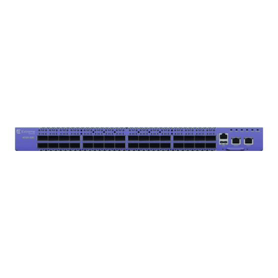
LEDs and their operation, see 8720 Switch LEDs on page 62 section of the guide. The following images show the front and rear views of an 8720 Switch. Figure 1: 8720 Switch front view Figure 2: 8720 Switch rear view... -
Page 15: Nonport-Side View Of The 8720 Switch
MGMT2 - CPU and BMC (secondary) MGMT1 - Direct to CPU (primary) All of the front-panel ports on the 8720-32C switch operate in either 100 gigabit or 40 gigabit mode, and each port supports multiple data lanes through the use of breakout cables. -
Page 16: Device Management Options
Command line Ethernet or serial Management Configuration interface (CLI) connection Guide Extreme SLX-OS REST or NETCONF/ Ethernet Management Configuration YANG APIs. connection Guide Extreme SLX-OS Standard SNMP Ethernet or serial Management Configuration applications connection Guide Extreme 8720 Switch Hardware Installation Guide... -
Page 17: Power Supplies
Power Supplies for Use with Your Switch Each 8720 switch runs with two replaceable internal power supply modules that provide all of the power needed for the switch to operate. You can remove one power supply module without interrupting the switch's operation. Supported power supply configurations include two 750 W AC power supply modules, two 750 W DC power supply modules, or one 750 W AC and one 750 W DC power supply module. -
Page 18: 750 W Ac Power Supply
750W AC power supply - back-to-front airflow (part no. XN-ACPWR-750W-R) Note AC power input cords are not provided with AC power supplies. You can order an appropriate cord from Extreme Networks or from your local supplier. The power cord must meet the requirements listed in Power Cord Requirements... -
Page 19: Preparing For The Installation
35 Preparing for the Installation Before you install your Extreme Networks equipment, careful planning can help ensure that it is used effectively and help prepare you for future growth. Only qualified service personnel should install, maintain, or remove a switch, chassis, or its components. -
Page 20: Operating Environment Requirements
This section lists resources for obtaining additional information. For information about major building codes, consult the following organization: International Code Council (ICC) 5203 Leesburg Pike Falls Church, VA 22041 USA www.iccsafe.org Extreme 8720 Switch Hardware Installation Guide... -
Page 21: Setting Up The Wiring Closet
Use appropriate AC or DC power, power distribution, and grounding for your specific installation. • Use a vinyl floor covering in your wiring closet. (Concrete floors accumulate dust, and carpets can cause static electricity.) Extreme 8720 Switch Hardware Installation Guide... -
Page 22: Controlling The Temperature
Alternately, you can restart the system immediately by removing and then restoring all line power to the system. Safeguards are built into all Extreme Networks switches and power supply units to minimize the risk of fire. Extreme 8720 Switch Hardware Installation Guide... -
Page 23: Controlling The Humidity Level
The rack must meet earthquake safety requirements equal to that of the installed chassis. • The mounting holes should be flush with the rails to accommodate the chassis. • The rack should support approximately 276 kg (600 lb). Extreme 8720 Switch Hardware Installation Guide... -
Page 24: Grounding The Rack
(61 cm) of space behind the mounted equipment. Extra room on each side is optional. Warning Extreme Networks switches do not have a switch for turning power to the unit on and off. For systems using an AC power supply, power to the switch is disconnected by removing the wall plug from the electrical outlet. -
Page 25: Securing The Rack
Evaluating and Meeting Cable Requirements Use professional consultants for site planning and cabling. Extreme Networks recommends using the Building Industry Consulting Service International (BICSI) Registered Communications Distribution Designer (RCDD), which is globally recognized as a standard in site planning and cabling. -
Page 26: Installing Cable
• Assign a unique identification number to each equipment rack. • Identify all wiring closets by labeling the front panel of your Extreme Networks equipment and other hardware. • Keep accurate and current cable identification records. - Page 27 Every cable has a minimum bend radius, example, and fibers will be damaged if the cables are bent too sharply. It is also important not to stretch the cable during installation. Extreme Networks recommends that the bend radius for fiber optic cable Extreme 8720 Switch Hardware Installation Guide...
- Page 28 Table 12: Cable Distances and Types Standard Media Type MHz•km Maximum Rating Distance (Meters) 1000BASE-SX 50/125 µm multimode fiber (850nm optical window) 50/125 µm multimode fiber 62.5/125 µm multimode fiber 62.5/125 µm multimode fiber Extreme 8720 Switch Hardware Installation Guide...
- Page 29 10/125 µm single-mode fiber – 40,000 (1550nm optical window) 1 Proprietary to Extreme Networks. Connections between two Extreme Networks 1000BASE-LX interfaces that use 10/125 µm single-mode fiber can use a maximum distance of 10,000 meters. Extreme 8720 Switch Hardware Installation Guide...
- Page 30 – cable 10BASE-T Category 3 and higher UTP – cable The following tables below list the Extreme Networks 100Gb Direct-Attach Cables and the Extreme Networks 40Gb Direct-Attach Cables Table 13: Extreme Networks 100Gb Direct-Attach Cables Cable Type Part Number Length...
-
Page 31: Using Rj45 Connector Jackets
• Crowded cable installation, which can cause connectors to pop out of the port. 2 Proprietary to Extreme Networks. Connections between two Extreme Networks 1000BASE-LX interfaces that use 10/125 µm single-mode fiber can use a maximum distance of 10,000 meters. -
Page 32: Preventing Radio Frequency Interference (Rfi)
Routing UTP cable near electrical transformers In areas or applications where these situations cannot be avoided, use fiber optic cabling or shielded twisted pair cabling. Meeting Power Requirements Observe the following requirements and precautions for powering your hardware. Extreme 8720 Switch Hardware Installation Guide... -
Page 33: Power Supply Requirements
Most ExtremeSwitching devices do not ship with power cords. Visit www.extremenetworks.com/product/powercords/ for information on selecting and purchasing the correct power cords for use with specific Extreme Networks equipment. The web page provides specifications for power cords in each country so that you can purchase cords locally. - Page 34 UPS transition time is sometimes called UPS transition times vary between UPS models and implementations, but shorter transition times are preferred. For Extreme Networks stacking products, we recommend a UPS transition time of 20 milliseconds or less to ensure optimum performance and minimize service interruptions.
-
Page 35: Following Applicable Industry Standards
For more information, see the following ANSI/TIA/EIA standards: • ANSI/TIA/EIA-568-A—the six subsystems of a structured cabling system • ANSI/TIA/EIA-569-A—design considerations • ANSI/TIA/EIA-606—cabling system administration • ANSI/TIA/EIA-607—commercial building grounding and bonding requirements You can access these standards at: www.ansi.org or www.tiaonline.org. Extreme 8720 Switch Hardware Installation Guide... -
Page 36: Installing Your Device
57 Connecting Network Interface Cables on page 58 Installing Your Switch Before you attempt to install or remove an Extreme Networks switch, read the precautions in Safety Considerations for Installing Switches on page 37. Extreme Networks switches fit into standard 19-inch equipment racks. -
Page 37: Safety Considerations For Installing Switches
19 and ensure that you have the appropriate people and tools on hand. Installing Extreme Networks switches is easiest when there are two people to maneuver the switch and attach mounting hardware. Provide enough space in front of and behind the switch so that you can service it easily. -
Page 38: Attaching The Switch To A Rack
44 Note • When you install Extreme Networks switches, we recommend that you have two people to maneuver the switch and the mounting hardware. • Take care to load the rack so that it is not top-heavy. Start installing equipment at the bottom and work up. - Page 39 Attaching a Mounting Bracket to One Side of the Switch Housing figure Figure 9: Attaching a Mounting Bracket to One Side of the Switch Housing 5. Repeat step 4 to attach the other mounting bracket to the other side of the housing. Extreme 8720 Switch Hardware Installation Guide...
- Page 40 See the figure to the Front Rack Post . Figure 10: Attaching the Slider Assembly to the Front Rack Post b. Extend the slider assembly until its rear clamp fits around the rear rack post. Extreme 8720 Switch Hardware Installation Guide...
- Page 41 Rear Rack Post . Figure 11: Attaching the Slider Assembly to the Rear Rack Post 7. Repeat step 6 to attach the other slider assembly to the front and rear rack posts on the other side. Extreme 8720 Switch Hardware Installation Guide...
- Page 42 11. Push gently until both mounting brackets engage with the slider assemblies. See Engaging the Mounting Brackets with the Rail Assemblies . the Figure Figure 13: Engaging the Mounting Brackets with the Rail Assemblies Extreme 8720 Switch Hardware Installation Guide...
- Page 43 Pushing the Mounting Brackets into the Rail Assemblies . See the Figure Figure 14: Pushing the Mounting Brackets into the Rail Assemblies Completed Installation: Switch in The completed assembly is shown in the Figure 4-Post Rack . Extreme 8720 Switch Hardware Installation Guide...
-
Page 44: Attaching The Switch To A Two-Post Rack
The side of the switch has different sets of holes for attaching mounting brackets in either configuration. Brackets for a two-post mount are not included in the box with your switch. However, they can be ordered separately using part number XN-2P-RKMT299. Extreme 8720 Switch Hardware Installation Guide... - Page 45 Attaching a Short even with the front of the switch, as shown in the figure below: Mounting Bracket (Ear): Front of Switch . Figure 16: Attaching a Short Mounting Bracket (Ear): Front of Switch Extreme 8720 Switch Hardware Installation Guide...
- Page 46 Orient it so that its flange (ear) rests against the rack post. Attaching a Long Mounting Bracket: Front of Switch and See the diagrams below: Attaching a Long Mounting Bracket: Middle of Switch . Extreme 8720 Switch Hardware Installation Guide...
- Page 47 Installing Your Device Attaching the Switch to a Two-Post Rack Figure 18: Attaching a Long Mounting Bracket: Front of Switch Extreme 8720 Switch Hardware Installation Guide...
- Page 48 6. Secure the flanges (ears) on both sides of the switch to the rack posts, using screws that are appropriate for the rack. (Rack-mounting screws are not provided.) Two-Post Front Mount: The completed installation is shown in the diagrams below: Complete and Two-Post Mid-Mount: Complete . Extreme 8720 Switch Hardware Installation Guide...
- Page 49 Installing Your Device Attaching the Switch to a Two-Post Rack Figure 20: Two-Post Front Mount: Complete Figure 21: Two-Post Mid-Mount: Complete Extreme 8720 Switch Hardware Installation Guide...
-
Page 50: Installing Optional Components
If your switch does not come with an installed internal power supply, you can install one or two power supplies. The 8720 Switch supports 750 W power supply units using either AC or DC power. Follow the instructions in the following sections to install the appropriate power supply and connect power to the switch. - Page 51 2. Verify that the new power supply is right side up. 3. Verify that the new power supply's airflow direction (front-to-back or back-to-front) is compatible with the other installed power supply (if any) and with the installed fan modules. Extreme 8720 Switch Hardware Installation Guide...
- Page 52 If power supplies are not installed in both power supply bays, be sure to install a cover over the unoccupied bay. Unoccupied bays must always be covered to maintain proper system ventilation and EMI levels. Extreme 8720 Switch Hardware Installation Guide...
- Page 53 AC power cord into the AC power supply. To install a second power supply, repeat this procedure. When you are finished, follow the steps in Powering up the Switch on page 57 . Extreme 8720 Switch Hardware Installation Guide...
-
Page 54: Installing A 750 W Internal Dc Power Supply
You will need two cable wires for each installed DC power supply: one input cable and a grounding cable. We recommend that each cable have differently colored insulation, as described in "Required Tools and Materials for Installing a 750 W DC Power Supply." Extreme 8720 Switch Hardware Installation Guide... - Page 55 4. Carefully slide the power supply all the way into the power supply bay. 5. Push the power supply in until the latch snaps into place. Caution Do not slam the power supply into the switch. 6. To install a second power supply, repeat the procedure. Extreme 8720 Switch Hardware Installation Guide...
- Page 56 Attach mm ring lug to the 6 AWG ground wire. b. Secure the ring lug with a 5mm hex socket and tighten. c. Gently tug the ground wire to make sure it is fastened securely. Extreme 8720 Switch Hardware Installation Guide...
-
Page 57: Powering Up The Switch
An AC power is not included with the AC power supply. You can purchase AC power cords for use in the US and Canada from Extreme networks or from your local supplier. The cord must meet the requirements listed in... -
Page 58: Connecting Network Interface Cables
5. Repeat step 1 through step 5 for the remaining cables on this or other switches or I/O modules. 6. Dress and secure the cable bundle to provide appropriate strain relief and protection against bends and kinks. Extreme 8720 Switch Hardware Installation Guide... -
Page 59: Activating And Verifying The Switch
2. Connect the RJ-45 serial cable provided with the device to the management Ethernet port of the device. Shown below are the Port-side views of the 8720 switch: Figure 25: Port-side view of the 8720-32C Switch 1 = 40Gbps/100Gbps QSFP+/QSFP28 Ethernet... -
Page 60: Configuring The Switch For Use
2. Press Enter to step through a procedure to change the passwords as shown in the following example. To skip modifying the password, press Ctrl+C. Warning: Access to the Root and Factory accounts may be required for proper support the switch. Please ensure the Root Extreme 8720 Switch Hardware Installation Guide... - Page 61 Passwords are case-sensitive, and they are not displayed when you enter them Extreme SLX-OS on the command line. For more information on passwords, refer to Security Configuration Guide for the 8720 device. The switch is ready for use. Extreme SLX-OS Layer 2 Switching To configure other switch features, see Configuration Guide .
-
Page 62: Monitoring The Switch
750 W DC Power Supply LEDs on page 64 8720 Switch LEDs The following illustrations show the port-side view of the 8720 switch showing the port and system LEDs. Figure 26: Port-side view of the 8720-32C Switch 1 = 40Gbps/100Gbps QSFP+/QSFP28 Ethernet... -
Page 63: 8720-32C Leds For Data Ports (1-32)
Monitoring the Switch 8720-32C LEDs for Data Ports (1-32) 8720-32C LEDs for Data Ports (1-32) Table 16: LEDs for Data Ports (1-32) Port Configuration Color/State Meaning 100 Gb Steady green Port OK or 4x25 Gb Blinking green Port transmitting or receiving... -
Page 64: 750 W Ac Power Supply Leds
(Solid) No PSU fault OUT OK DC output DC output OK (Green) Good (solid) Off or DC output fail Blinkin IN OK DC input DC input OK (Green) Good "IN DC input fail OK" Extreme 8720 Switch Hardware Installation Guide... -
Page 65: Removing And Replacing Components
All installed power supplies must have the same airflow direction (front-to-back or back-to-front) and must also match the airflow direction of the fan modules. To replace one or both AC internal power supplies in an 8720 switch, follow the steps in Installing a 750 W Internal AC Power Supply on page 50. -
Page 66: Removing The Switch From The Rack
Attaching the Switch to a Four-Post Rack on page 38 • Attaching the Switch to a Two-Post Rack on page 44 1. Disconnect the switch from its power source or sources. 2. Remove all cables and transceivers. Extreme 8720 Switch Hardware Installation Guide... - Page 67 Carefully slide the switch out of the slider assembly and place it on a flat surface. You can leave the slider assemblies in place. If you want to remove them, continue with the next step . Extreme 8720 Switch Hardware Installation Guide...
- Page 68 On one of the slider assemblies, push the rear clamp until it separates from the rear rack post. Removing the Slider Assembly: Rear Rack Post . See the diagram below - Figure 28: Removing the Slider Assembly: Rear Rack Post Extreme 8720 Switch Hardware Installation Guide...
- Page 69 If you plan to use the switch again later, we recommend storing it with the mounting brackets attached. Extreme 8720 Switch Hardware Installation Guide...
-
Page 70: Technical Specifications
The SLX 8720 Switch includes the following switch models: Part number Description 8720-32C 8720-32C Switch with two empty power supply slots, and six empty fan slots. Supports 32x100/40GE 8720-32C-AC-F 8720-32C Switch AC with Front to Back Airflow. Supports 32x100/40GE with dual power supplies, six fans 8720-32C-AC-R 8720-32C Switch AC with Back to Front Airflow. - Page 71 Table 21: 8720 Switch Unpackaged Weight 8720-32C (base with no PSU or fans) 7.37 kg (16.24 lb) 8720-32C switch with two AC PSUs (-F and -R 9.7 kg (21.32 lb) models) 8720-32C switch with two DC PSUs (-F and -R 9.72 kg (21.43 lb)
-
Page 72: Acoustic Specifications
Tray 6 Fan 1 high speed Unknown* Tray 6 Fan 2 medium speed Unknown* * - The color of the tab on the fan tray indicates the airflow direction: • Red = Front-to-Back • Blue = Back-to-Front Extreme 8720 Switch Hardware Installation Guide... -
Page 73: Power Options
165 W 159.8 W 313.6 W Stress mode 100% 100% 207.8 W 204.5 W 406.o W Power and Heat Dissipation Table 28: 8720 Switch Power and Heat Dissipation Switch Model Minimum Heat Minimum Power Maximum Maximum Dissipation Consumption Heat Power... -
Page 74: Mean Time Between Failures (Mtbf)
Mean Time Between Failures (MTBF) Technical Specifications Mean Time Between Failures (MTBF) Table 29: 8720 Switch Mean Time Between Failures (MTBF) Switch Model Mean Time Between Failures 8720-32C-AC-F 428,807 hrs @ 25°C 8720-32C-AC-R 476,814 hrs @ 25°C 8720-32C-DC-F 476,813 hrs @ 25°C 8720-32C-DC-R 476,813 hrs @ 25°C... -
Page 75: Standards
EN 55024 EN 55035 EN 55011 (Group 1, Class A) EN 61000-6-2 EN 61000-6-4 EN 61000-3-2 Class A EN 61000-3-3 EN 61000-4-2 EN 61000-4-3 EN 61000-4-4 EN 61000-4-5 EN 61000-4-6 EN 61000-4-8 EN 61000-4-11 Extreme 8720 Switch Hardware Installation Guide... - Page 76 EN/ETSI 300 019 (Environmental for Telecommunications) MEF9 and MEF14 certified for EPL, EVPL, and ELAN Table 34: IEEE 802.3 Media Access Standards IEEE 802.3ab 1000BASE-T IEEE 802.3z 1000BASE-X IEEE 802.3ae 10GBASE-X IEEE 802.3ba 40GBASE-X Extreme 8720 Switch Hardware Installation Guide...
-
Page 77: Environmental Data
14 drops minimum on sides and corners at 42 in (<15 kg box) 750 W Power Supplies Technical Specifications Four 750 W power supply units are available for use with 8720 switches: • 750W AC power supply - front-to-back airflow (part no. XN-ACPWR-750W-F) •... - Page 78 Line frequency range 47 to 63 Hz Maximum inrush current 35 A Output +12 V, 61.5 A +12 Vsb, 3 A Total output power not to exceed 750W Power supply input socket IEC 320 C14 Extreme 8720 Switch Hardware Installation Guide...
- Page 79 Table 42: Environmental Specifications (All Power Supply Units) Operating temperature 0°C to 55°C (normal operation) Storage temperature -40°C to 70°C Operating humidity 20% to 90% relative humidity, non-condensing 30 m/s 2 (3 G) Operational shock Extreme 8720 Switch Hardware Installation Guide...
-
Page 80: Power Cord Requirements For Ac-Powered Switches And Ac Power Supplies
For cords up to 6 feet (2 m) long, the wire size must be 18 AWG (.75 mm ) minimum; over 6 feet, the minimum wire size is 16 AWG (1.0 mm For details about obtaining AC power cords for use in your country, refer to http:// www.extremenetworks.com/product/powercords/. Extreme 8720 Switch Hardware Installation Guide... -
Page 81: Safety And Regulatory Information
Only trained and qualified service personnel (as defined in IEC 60950-1 and AS/NZS 3260) should install, replace, or perform service to Extreme Networks switches and their components. Qualified personnel have read all related installation manuals, have the... -
Page 82: General Safety Precautions
Make sure that your power supplies meet the site DC power or AC power requirements of all the network equipment. • Racks for Extreme Networks equipment must be permanently attached to the floor. Failure to stabilize the rack can cause the rack to tip over when the equipment is removed for servicing. -
Page 83: Cable Routing For Lan Systems
Safety and Regulatory Information Cable Routing for LAN Systems the defective unit to Extreme Networks for repair or replacement, unless otherwise instructed by an Extreme Networks representative. • To remove power from the system, you must unplug all power cords from wall outlets. -
Page 84: Installing Power Supply Units And Connecting Power
When you install DC power supplies or connect DC power: • Extreme Networks DC power supplies do not have switches for turning the unit on and off. Make sure that the DC circuit is de-energized before connecting or disconnecting the DC power cord at the DC input power socket. -
Page 85: Selecting Power Supply Cords
You can purchase a power cord for your product and for your specific country from your local Extreme Networks Channel Account Manager or Sales Manager, or you can purchase a cord from your local supplier. Requirements for the power cord are listed in the Technical Specifications for your product. - Page 86 Il y a risque d’explosion si la pile est remplacée par un type de pile incorrect. Éliminez les piles usées en conformité aux règlements locaux d'élimination des piles. Extreme 8720 Switch Hardware Installation Guide...
-
Page 87: Regulatory Statements
Electromagnetic Compatibility (EMC) Directive 2014/30/EU • Low Voltage Directive (LVD) 2014/35/EU • EN 55032/EN 55024 (European Immunity Requirements) EN61000-3-2/JEIDA (European and Japanese Harmonics Spec) ◦ EN61000-3-3 ◦ China ROHS For more information, see https://www.extremenetworks.com/company/legal/ restriction-of-hazardous-substances/. Extreme 8720 Switch Hardware Installation Guide... -
Page 88: Bsmi Statement (Taiwan)
Canadian requirements This Class A digital apparatus meets all requirements of the Canadian Interference- Causing Equipment Regulations, ICES-003 Class A. Cet appareil numérique de la classe A est conforme à la norme NMB-003 du Canada. Extreme 8720 Switch Hardware Installation Guide... -
Page 89: China Ccc Statement
Federal Communications Commission (FCC) Notice This device complies with Part 15 of the FCC rules. Operation is subject to the following two conditions: (1) this device may not cause harmful interference, and (2) this Extreme 8720 Switch Hardware Installation Guide... -
Page 90: Germany Statement
This is a Class A product based on the standard of the VCCI Council. If this equipment is used in a domestic environment, radio interference may occur, in which case the user may be required to take corrective actions. Extreme 8720 Switch Hardware Installation Guide... -
Page 91: Japan Power Cord
Regulatory Statements Japan power cord Japan power cord English translation of above statement ATTENTION: Never use the power cord packed with your equipment for other products. Extreme 8720 Switch Hardware Installation Guide... -
Page 92: Cautions And Danger Notices
Un mensaje de precaución le alerta de situaciones que pueden resultar peligrosas para usted o causar daños en el hardware, el firmware, el software o los datos. Extreme 8720 Switch Hardware Installation Guide... -
Page 93: General Cautions
Aucune pièce du bloc de l'alimentation ou du ventilateur ne peut être réparée par l'utilisateur. PRECAUCIÓ Si se desmonta cualquier pieza del módulo de fuente de alimentación y ventiladores, la garantía y las certificaciones normativas quedan Extreme 8720 Switch Hardware Installation Guide... - Page 94 PRECAUCIÓ Para evitar que se dañe el puerto serie, mantenga la cubierta colocada sobre el puerto cuando no lo utilice. Caution Never leave tools inside the chassis. Lassen Sie keine Werkzeuge im Chassis zurück. Extreme 8720 Switch Hardware Installation Guide...
- Page 95 PRECAUCIÓ Si no instala un módulo o un fuente de alimentación en la ranura, deberá mantener el panel de ranuras en su lugar. Si pone en Extreme 8720 Switch Hardware Installation Guide...
- Page 96 VORSICHT Alle Geräte mit DC-Netzteil sind nur für die Installation in Bereichen mit beschränktem Zugang gedacht. Ein Bereich mit beschränktem Zugang ist ein Ort, zu dem nur ausgebildetes Extreme 8720 Switch Hardware Installation Guide...
- Page 97 à l'électricité statique dans leur emballage protecteur tant qu'ils n'ont pas été installés. PRECAUCIÓ La electricidad estática puede dañar el chasis y otros dispositivos electrónicos. A fin de impedir que se produzcan daños, conserve los Extreme 8720 Switch Hardware Installation Guide...
- Page 98 (amp) de todos los instrumentos instalados en el mismo circuito que el instrumento. Compare esta suma con el límite nominal para el circuito. Las capacidades nominales de Extreme 8720 Switch Hardware Installation Guide...
-
Page 99: Danger Notices
Des étiquettes de sécurité sont posées directement sur le produit et vous avertissent de ces conditions ou situations. Una advertencia de peligro indica condiciones o situaciones que pueden resultar potencialmente letales o extremadamente peligrosas. También habrá etiquetas Extreme 8720 Switch Hardware Installation Guide... - Page 100 Danger Notices Cautions and Danger Notices de seguridad pegadas directamente sobre los productos para advertir de estas condiciones o situaciones. Extreme 8720 Switch Hardware Installation Guide...
-
Page 101: General Dangers
Jetez/recyclez les batteries conformément aux normes locales. PELIGRO Las baterías usadas para respaldo de RTC/NVRAM no se encuentran en areas de acceso del operador. Existe riesgo de explosión si una batería Extreme 8720 Switch Hardware Installation Guide... - Page 102 PELIGRO Antes de comenzar la instalación, consulte las precauciones en la sección “Power Precautions” (Precauciones sobre corriente). Extreme 8720 Switch Hardware Installation Guide Warning Be careful not to accidently insert your fingers into the fan tray while removing it from the chassis. The fan may still be spinning at a high speed.
- Page 103 レーザ放射 光学器具で直接ビームを見ないこと クラス1 M レーザ製品 警告 Warning Use only optical transceivers that are qualified by Extreme Networks, Inc. and comply with the FDA Class 1 radiation performance requirements defined in 21 CFR Subchapter I, and with IEC 60825 and EN60825. Optical products that do not comply with these standards might emit light that is hazardous to the eyes.
-
Page 104: Glossary
Glossary Extreme 8720 Switch Hardware Installation Guide... -
Page 105: Index
DC power supply brackets, for mounting in rack 44, 66 connecting ground wire 56 building codes 20 LEDs 64 Building Industry Consulting Service International. design standards 35 see BICSI distances cables 28, 31 documentation feedback 9 Extreme 8720 Switch Hardware Installation Guide... - Page 106 LEDs feedback 9 750 W AC power supply 64 fiber optic cable 750 W DC power supply 64 bend radius 27 8720 62, 63 connecting 58 logging in to the switch 60 handling 27 installing 27 first switch login 60...
- Page 107 Index operating environment requirements 22 safety optical cables requirements 81 installing 50 service access to the rack 24 optical transceivers signal quality 32 installing 50 site planning 19 optional components site preparation 37 installing 50 slack in cable 26 space requirements, rack 24 specifications 750 W AC power supply 78 planning...
- Page 108 Index warnings 6 wire connecting 56 wiring closet electrostatic discharge (ESD) 23 floor coverings 21 grounding 21 humidity 23 rack, securing 25 temperature 22 wiring terminals 24...
Need help?
Do you have a question about the 8720 and is the answer not in the manual?
Questions and answers