Extreme Networks BlackDiamond 8806 Hardware Installation Manual
Blackdiamond 8800 series
Hide thumbs
Also See for BlackDiamond 8806:
- Hardware installation manual (180 pages) ,
- Hardware installation manual (202 pages) ,
- Hardware installation manual (204 pages)
Table of Contents
Advertisement
Quick Links
Advertisement
Table of Contents

Subscribe to Our Youtube Channel
Related Manuals for Extreme Networks BlackDiamond 8806


Summary of Contents for Extreme Networks BlackDiamond 8806
- Page 1 BlackDiamond 8800 Series Switches Hardware Installation Guide BlackDiamond 8806 Switch BlackDiamond 8810 Switch Extreme Networks, Inc. 3585 Monroe Street Santa Clara, California 95051 (888) 257-3000 (408) 579-2800 http://www.extremenetworks.com Published: March 2010 Part Number: 100284-00 Rev. 07...
- Page 2 ReachNXT, Sentriant, ServiceWatch, Summit, SummitStack, Triumph, Unified Access Architecture, Unified Access RF Manager, UniStack, the Extreme Networks logo, the Alpine logo, the BlackDiamond logo, the Extreme Turbodrive logo, the Summit logos, and the Powered by ExtremeXOS logo are trademarks or registered trademarks of Extreme Networks, Inc.
-
Page 3: Table Of Contents
Overview of the BlackDiamond 8800 Series Switches ..............13 Full-Duplex Support ........................14 Management Ports ........................14 External Compact Flash Memory Card ..................14 BlackDiamond 8806 Chassis .....................15 BlackDiamond 8810 Chassis .....................16 Chapter 2: BlackDiamond 8000 Series Modules ................19 Overview of the BlackDiamond 8000 Series Modules..............19 Management Switch Modules (MSM) ..................21... - Page 4 Port LEDs on PoE Modules (G48P, G48Pe, and G48Tc, G48Te2, or 8500-G48T-e or 8900- G48T-xl with S-POE Card)....................52 Chapter 3: Power Supply Units for BlackDiamond 8800 Series Switches.......... 53 Overview of BlackDiamond 8800 Series Power Supplies ...............53 Extreme Networks 700/1200 W AC PSU ..................54 LEDs..........................55 Power Supply Cords......................55 Fuse ............................55 Specifications ........................56...
- Page 5 Installing an Extreme Networks AC PSU ..................100 Required Tools and Equipment...................101 Installing the PSU ......................101 Removing or Replacing an Extreme Networks AC PSU ............103 Installing an Extreme Networks 1200 W DC PSU ...............104 Required Tools and Equipment...................104 Installing the DC Wiring .....................104 Installing a 1200 W DC PSU ....................105...
- Page 6 Installing the BlackDiamond 8810 AC Power Cord Retainer ..........133 Disconnecting a BlackDiamond 8810 AC Power Cord ............135 BlackDiamond 8806 AC Power Cord Retainer ................136 Installing the BlackDiamond 8806 AC Power Cord Retainer ..........136 Removing the BlackDiamond 8806 AC Power Cord Retainer..........138 Chapter 10: BlackDiamond PSU Covers ..................139 Required Tools........................139...
- Page 7 Chapter 13: Repacking a BlackDiamond 8800 Series Chassis ............159 Safety Information ........................159 Required Tools and Equipment....................160 Repacking the BlackDiamond 8810 Chassis ................160 Repacking the BlackDiamond 8806 Chassis ................164 Part 5: Appendices Appendix A: Safety Information ....................169 Considerations Before Installing ....................169 Installing Power Supply Units....................170...
- Page 8 Contents BlackDiamond 8800 Series Switches Hardware Installation Guide...
-
Page 9: Preface
Extreme Networks BlackDiamond 8800 series switches. NOTE If the information in the installation note or release note shipped with your Extreme Networks switch differs from the information in this guide, follow the installation note or release note. Intended Audience This guide is intended for use by network administrators responsible for installing and setting up network equipment. -
Page 10: Related Publications
Summit Family Switches Hardware Installation Guide ● ● Extreme Networks Pluggable Interface Modules Installation Guide Documentation for Extreme Networks products is available from the Extreme Networks website at the following location: http://www.extremenetworks.com/go/documentation You can select and download the following Extreme Networks documentation from the Documentation... -
Page 11: Part 1: About The Blackdiamond 8800 Series Switches
About the BlackDiamond 8800 Series Switches... -
Page 13: Chapter 1: About The Blackdiamond 8800 Series Switches
Load sharing on multiple ports ● The BlackDiamond 8800 series switches include two chassis models: BlackDiamond 8806 chassis, with slots for installing one or two management modules and up to five ● I/O modules BlackDiamond 8810 chassis, with slots for installing one or two management modules and up to ●... -
Page 14: Full-Duplex Support
Most ports on an Extreme Networks switch will auto-negotiate duplex operation in the default configuration. Gigabit Ethernet fiber ports and 10-Gigabit Ethernet ports operate only in full-duplex mode in accordance with technical standards. -
Page 15: Blackdiamond 8806 Chassis
● One connector for an ESD-preventive wrist strap ● Depending on the MSMs and I/O modules installed, the BlackDiamond 8806 chassis can support up to 128 gigabits per second of bandwidth per slot. Figure 1 shows the front of a BlackDiamond 8806 chassis equipped with two MSMs and three I/O modules. -
Page 16: Blackdiamond 8810 Chassis
About the BlackDiamond 8800 Series Switches Figure 2: Rear Panel of the BlackDiamond 8806 Chassis PSU / fan controllers Grounding point EX_128A The rear panel of the BlackDiamond 8806 chassis provides: Chassis serial number ● Ethernet MAC address of the switch ●... -
Page 17: I/O Modules
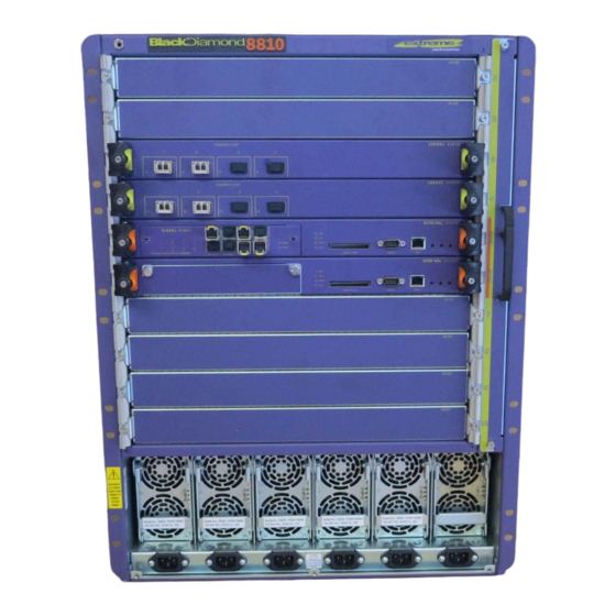
Figure 1 shows the front of a BlackDiamond 8810 chassis equipped with two MSMs and three I/O modules. Figure 3: Front of the BlackDiamond 8810 Chassis ESD wrist strap connector Fan tray I/O module slots MSM module slot I/O module slots Power supplies Power cord connectors... - Page 18 About the BlackDiamond 8800 Series Switches The rear panel of the BlackDiamond 8810 chassis provides: Chassis serial number ● Ethernet MAC address of the switch ● Symbols of safety certification ● Access to the PSU/fan controllers ● Attachment point for optional chassis ground ●...
-
Page 19: Chapter 2: Blackdiamond 8000 Series Modules
BlackDiamond 8000 Series Modules This chapter describes modules for the BlackDiamond 8800 series switches and includes the following sections: Overview of the BlackDiamond 8000 Series Modules on page 19 ● Management Switch Modules (MSM) on page 21 ● I/O Modules on page 25 ●... - Page 20 BlackDiamond 8000 Series Modules Although modules from different series can generally be used together in the same BlackDiamond 8800 series chassis, certain restrictions apply. Table Table 6, and Table 7 show supported and unsupported module series combinations. Table 5: BlackDiamond 8000 Series Module Compatibility—8800 Series with 8900 Series 8900 Series Modules 8800 Series 8900-...
-
Page 21: Management Switch Modules (Msm)
When a switch boots with two MSMs installed, the MSM in the lower-numbered slot becomes the ● primary MSM. In the BlackDiamond 8810 switch this is slot 5; in the BlackDiamond 8806 switch, this is slot 3. When a switch boots with a single MSM (regardless of the slot position), it is selected as the primary ●... -
Page 22: Msm Physical Features
BlackDiamond 8000 Series Modules MSM Physical Features Figure 5 shows the 8500-MSM24. Figure 5: 8500-MSM24 o d u l e s t a t u s L E D s C o n s o l e p o r t C o m p a c t f l a s h p o r t B D _ 2 2 9... - Page 23 Figure 8 shows the MSM-48c. Figure 8: MSM-48c Module status LEDs Console port Compact flash MGMT port ASP_051 Figure 9 shows the 8900-MSM128 module. Figure 9: 8900-MSM128 o d u l e s t a t u s L E D s C o n s o l e p o r t Management Switch Module C o m p a c t f l a s h...
-
Page 24: Msm Leds
BlackDiamond 8000 Series Modules The 8500-MSM24, MSM-48c and 8900-MSM128 modules have a slot for one of the following option cards: S-G8Xc—Adds eight 1-gigabit SFP data ports to the MSM. These data ports operate the same as the ● ports on the G24Xc I/O module. (See “G24Xc I/O Module”... -
Page 25: I/O Modules
I/O Modules The following series of I/O modules are available for the BlackDiamond 8800 series switches: BlackDiamond 8500 series I/O modules (see page ● BlackDiamond 8800 series I/O modules: ● BlackDiamond 8800 original series I/O modules (see page ■ BlackDiamond 8800 a-series I/O modules (see page ■... -
Page 26: Blackdiamond 8500 Series I/O Modules
BlackDiamond 8000 Series Modules BlackDiamond 8500 Series I/O Modules The BlackDiamond 8500 series modules include: 8500-G48T-e ● 8500-G24X-e ● CAUTION ExtremeXOS builds earlier than version 12.3.x do not support the BlackDiamond 8500 series modules. If you attempt to install one of these I/O modules before upgrading the software on your MSM the module will not be recognized by the software and it will not power up. -
Page 27: 8500-G24X-E
8500-G24X-e The 8500-G24X-e I/O module (Figure 11) has 24 unpopulated SFP-based 1-gigabit Ethernet ports. Figure 11: 8500-G24X-e I/O Module 1 0 0 0 B A S E - X p o r t s o d u l e s t a t u s L E D s B D _ 2 3 1 In the default configuration of the 8500-G48T-e I/O module, all ports: Are added to the default VLAN as untagged... -
Page 28: Blackdiamond 8800 Original Series I/O Modules
For information about the LEDs and their activity on the G24X module, see “I/O Module LEDs” on page 50. For information about the SFP modules, see the Extreme Networks Pluggable Interface Modules Installation Guide. BlackDiamond 8800 Series Switches Hardware Installation Guide... -
Page 29: 10G4X I/O Module
For information about the LEDs and their activity on the 10G4X I/O module, see “I/O Module LEDs” on page 50. For information about the XENPAK interfaces, see the Extreme Networks Pluggable Interface Modules Installation Guide. BlackDiamond 8800 Series Switches Hardware Installation Guide... -
Page 30: G48T I/O Module
BlackDiamond 8000 Series Modules G48T I/O Module The G48T I/O module (Figure 14) has 48 autosensing 10/100/1000BASE-T ports that use standard RJ-45 connectors. Figure 14: G48T I/O Module 10/100/1000BASE-T ports Module status LEDs ASP037A In the default configuration of the G48T I/O module, all ports: Are added to the default VLAN as untagged ●... -
Page 31: G48P I/O Module
G48P I/O Module The G48P I/O module (Figure 15) has 48 autosensing 10/100/1000BASE-T ports that use standard RJ-45 connectors. In addition to the Ethernet connection, these ports can deliver Power over Ethernet (PoE) to an attached device using the same cable. The G48P I/O module supports the IEEE 802.3af PoE specification. -
Page 32: Blackdiamond 8800 A-Series I/O Modules
BlackDiamond 8000 Series Modules BlackDiamond 8800 a-Series I/O Modules The BlackDiamond 8800 a-series I/O modules include: G48Ta I/O Module on page 33 ● G48Xa I/O Module on page 34 ● 10G4Xa I/O Module on page 35 ● 10G4Ca I/O Module on page 36 ●... -
Page 33: G48Ta I/O Module
G48Ta I/O Module The G48Ta I/O module (Figure 16) has 48 autosensing 10/100/1000BASE-T ports that use standard RJ-45 connectors. Figure 16: G48Ta I/O Module 10/100/1000BASE-T ports Module status LEDs ASP048 In the default configuration of the G48Ta I/O module, all ports: Are added to the default VLAN as untagged ●... -
Page 34: G48Xa I/O Module
● For information about the LEDs and their activity on the G48Xa module, see “I/O Module LEDs” on page 50. For information about SFPs, see the Extreme Networks Pluggable Interface Modules Installation Guide. BlackDiamond 8800 Series Switches Hardware Installation Guide... -
Page 35: 10G4Xa I/O Module
For information about the LEDs and their activity on the 10G4Xa I/O module, see “I/O Module LEDs” on page 50. For information about the XFP interfaces, see the Extreme Networks Pluggable Interface Modules Installation Guide. BlackDiamond 8800 Series Switches Hardware Installation Guide... -
Page 36: 10G4Ca I/O Module
BlackDiamond 8000 Series Modules 10G4Ca I/O Module The 10G4Ca I/O module (Figure 18) has four 10-gigabit Ethernet ports that use CX4 interface connectors. Figure 19: 10G4Ca I/O Module 10G4Ca 10G4Ca 41613 10GBASE-CX4 Module status LEDs 10 Gbs ports BD_156 In the default configuration of the 10G4Ca I/O module, all ports: Are added to the default VLAN as untagged ●... -
Page 37: G48Tc I/O Module
G48Tc I/O Module The G48Tc I/O module (Figure 20) has 48 autosensing 10/100/1000BASE-T ports that use standard RJ-45 connectors. Figure 20: G48Tc I/O Module 1 0 / 1 0 0 / 1 0 0 0 B A S E - T p o r t s o d u l e s t a t u s L E D s A S P 0 5 1... -
Page 38: 10G4Xc I/O Module
BlackDiamond 8000 Series Modules 10G4Xc I/O Module The 10G4Xc I/O module (Figure 21) has four unpopulated XFP-based 10-gigabit Ethernet ports. Figure 21: 10G4Xc I/O Module Module status LEDs 10G4Xc 10G4Xc 41614 10GBASE-X XFP 10 Gbs ports BD_155 In the default configuration of the 10G4Xc I/O module, all ports: Are added to the default VLAN as untagged ●... -
Page 39: 10G8Xc I/O Module
10G8Xc I/O Module The 10G8Xc I/O module Figure 22 has eight unpopulated XFP-based 10-gigabit Ethernet ports. This module is over-subscribed 2:1. Figure 22: 10G8Xc I/O Module Module status LEDs 10G8Xc 10G8Xc 41615 10GBASE-X XFP 10 Gbs ports BD_155 In the default configuration of the 10G8Xc I/O module, all ports: Are added to the default VLAN as untagged ●... -
Page 40: G24Xc I/O Module
BlackDiamond 8000 Series Modules G24Xc I/O Module The G24Xc I/O module Figure 23 has 24 unpopulated SFP-based 1-gigabit Ethernet ports. Figure 23: G24Xc I/O Module 1000BASE-X ports Module status LEDs ASP049B In the default configuration of the G24Xc I/O module, all ports: Are added to the default VLAN as untagged ●... -
Page 41: G48Xc I/O Module
G48Xc I/O Module The G48Xc I/O module (Figure 24) has 48 unpopulated SFP-based 1-gigabit Ethernet ports. Figure 24: G48Xc I/O Module 1000BASE-X ports Module status LEDs ASP049A In the default configuration of the G48Xc I/O module, all ports: Are added to the default VLAN as untagged ●... -
Page 42: Blackdiamond 8800 E-Series I/O Modules
BlackDiamond 8000 Series Modules BlackDiamond 8800 e-Series I/O Modules The BlackDiamond 8800 e-series of I/O modules include: G48Te I/O Module on page 42 ● G48Pe I/O Module on page 43 ● G48Te2 I/O Module on page 44 ● CAUTION ExtremeXOS software builds earlier than version 11.5.0 do not support G48Te or G48Pe I/O modules. ExtremeXOS builds earlier than version 12.1 do not support the G48Te2 I/O module. -
Page 43: G48Pe I/O Module
G48Pe I/O Module The G48Pe I/O module (Figure 26) has 48 autosensing 10/100/1000BASE-T ports that use standard RJ-45 connectors. In addition to the Ethernet connection, these ports can deliver Power over Ethernet (PoE) to an attached device, using the same cable. The G48Pe I/O module supports the IEEE 802.3af PoE specification. -
Page 44: G48Te2 I/O Module
BlackDiamond 8000 Series Modules G48Te2 I/O Module The G48Te2 I/O module (Figure 25) has 48 autosensing 10/100/1000BASE-T ports that use standard RJ-45 connectors. Figure 27: G48Te2 I/O Module 1 0 / 1 0 0 / 1 0 0 0 B A S E - T p o r t s o d u l e s t a t u s L E D s A S P 0 5 2... -
Page 45: Blackdiamond 8900 Series Modules
BlackDiamond 8900 Series Modules The following 8900 series I/O modules are available: 8900-G96T-c (see page ● 8900-10G24X-c (see page ● 8900-10G8X-xl (see page ● 8900-G48T-xl (see page ● 8900-G48X-xl (see page ● CAUTION ExtremeXOS builds earlier than version 12.3 do not support the BlackDiamond 8900-G96T-c or 8900-10G24X-c modules. -
Page 46: 8900-G96T-C
BlackDiamond 8000 Series Modules 8900-G96T-c The 8900-G96T-c I/O module (Figure 28) has 96 10/100/1000BASE-T ports using MRJ21 connectors. Each connector provides six ports. NOTE The 8900-G96Tc module is not compatible with the 10G4X module. If an 8900-G96Tc module and a 10G4X module are installed in the same chassis, only one of these modules will function. -
Page 47: 8900-10G24X-C I/O Module
8900-10G24X-c I/O Module The 8900-10G24X-c I/O module (Figure 29) has 24 unpopulated SFP+-based 10-gigabit Ethernet ports Figure 29: 8900-10G24X-c I/O Module 1 0 - g i g a b i t p o r t s o d u l e s t a t u s L E D s B D _ 2 2 7 In the default configuration of the 8900-10G24X-c I/O module, all ports: Are added to the default VLAN as untagged... -
Page 48: 8900-10G8X-Xl I/O Module
BlackDiamond 8000 Series Modules 8900-10G8X-xl I/O Module The 8900-10G8X-xl I/O module (Figure 30) has eight unpopulated XFP-based 10-gigabit Ethernet ports. Figure 30: 8900-10G8X-xl I/O Module M o d u l e s t a t u s L E D s 1 0 G b s p o r t s D _ 2 7 9 In the default configuration of the 8900-10G8X-xl I/O module, all ports:... -
Page 49: 8900-G48T-Xl I/O Module
8900-G48T-xl I/O Module The 8900-G48T-xl I/O module (Figure 31) has 48 10/100/1000 1000BASE-T ports using standard RJ-45 connectors. Figure 31: 8900-G48T-xl I/O Module 1 0 / 1 0 0 / 1 0 0 0 B A S E - T p o r t s o d u l e s t a t u s L E D s B D _ 2 8 0... -
Page 50: 8900-G48X-Xl I/O Module
BlackDiamond 8000 Series Modules 8900-G48X-xl I/O Module The 8900-G48X-xl I/O module (Figure 32) has 48 unpopulated SFP-based 1-gigabit Ethernet ports. Figure 32: 8900-G48X-xl I/O Module 1 0 0 0 B A S E - X p o r t s o d u l e s t a t u s L E D s B D _ 2 8 1 In the default configuration of the 8900-G48X-xl I/O module, all ports:... -
Page 51: Module Leds
Module LEDs Table 10 describes the LED activity for all I/O modules that are installed in BlackDiamond 8800 series switches. Table 10: LED Meanings in I/O Modules for BlackDiamond 8800 Series Switches Color Indicates The optional PoE card is installed on the module. Present This LED is present only on the G48Tc, G48Te2, 8500-G48T-e, and 8900-G48T-xl modules. -
Page 52: Port Leds On Poe Modules (G48P, G48Pe, And G48Tc, G48Te2, Or 8500-G48T-E Or 8900-G48T-Xl With S-Poe Card)
BlackDiamond 8000 Series Modules NOTE Table 11 describes port LED activity for the G48Tc, G48Te2, 8500-G48T-e, and 8900-G48T-xl modules without an installed S-POE card. When these modules have an S-POE card installed, the port LEDs operate as described in Table Port LEDs on PoE Modules (G48P, G48Pe, and G48Tc, G48Te2, or 8500-G48T-e or 8900-G48T-xl with S-POE Card) This section describes the port LEDs for BlackDiamond 8000 series I/O modules that support PoE. -
Page 53: Chapter 3: Power Supply Units For Blackdiamond 8800 Series Switches
The chapter describes the power supply units used with the BlackDiamond 8800 series switches and includes the following sections: Overview of BlackDiamond 8800 Series Power Supplies on page 53 ● Extreme Networks 700/1200 W AC PSU on page 54 ● Extreme Networks 600/900 W AC PSU on page 57 ●... -
Page 54: Extreme Networks 700/1200 W Ac Psu
The AC input connection is located on the switch directly below each installed power supply. NOTE In a BlackDiamond 8806 system, the Extreme Networks 700W/1200 W AC PSU can be used with an Extreme Networks 600/900 W AC PSU in the same chassis. -
Page 55: Leds
Power Supply Cords The Extreme Networks 700/1200 W AC PSU(s) can be used with either a 110 V AC or a 220 V AC power supply cord. If you use a 110 V AC power supply cord, the maximum DC output power of the PSU is 700 W. -
Page 56: Specifications
Power Supply Units for BlackDiamond 8800 Series Switches Specifications The 700/1200 W AC PSU functions from 90 V to 264 V and 47 Hz to 63 Hz AC Input. Each PSU provides 700 W to the system if the AC input is in the 110 V low-line output power range and 1200 W to the system if the AC input is in the 220 V high-line output power range. -
Page 57: Extreme Networks 600/900 W Ac Psu
The AC input is located on the switch directly below each installed power supply. NOTE The Extreme Networks 600/900 W AC PSU can be used in combination with an Extreme Networks 700W/1200W AC PSU in the same BlackDiamond 8806 system. -
Page 58: Leds
Extreme Networks 600/900 W AC PSU for a complete replacement. WARNING! Field operators must not attempt to configure or replace fuses in Extreme Networks 600/900 W AC PSUs! In the event of failure, immediately return the defective Extreme Networks 600/900 W AC PSU for a complete replacement. -
Page 59: Specifications
Combining Different AC PSU Models When 600/900 W AC PSUs and 700/1200 W AC PSUs are combined in the same BlackDiamond 8806 chassis and are powered on, all PSUs will be budgeted down to the lower powered 600/900 W AC output values to avoid PSU shutdown due to over-current. -
Page 60: Extreme Networks 1200 W Dc Psu
Power Supply Units for BlackDiamond 8800 Series Switches Extreme Networks 1200 W DC PSU The Extreme Networks 1200 W DC UL-listed accessory power supply unit (Model number 60021/PS 2350) is compatible with the BlackDiamond 8800 series switches. The power supply bay in the BlackDiamond 8800 series switch can accommodate up to six hot-swappable 1200 W DC PSUs. -
Page 61: Minimum Software Required
Field operators must not attempt to open the 1200 W DC PSU enclosure for any reason; the PSU does not contain user-serviceable parts. In the event of failure, return the defective 1200 W DC PSU to Extreme Networks for repair or replacement. - Page 62 Power Supply Units for BlackDiamond 8800 Series Switches BlackDiamond 8800 Series Switches Hardware Installation Guide...
-
Page 63: Part 2: Installing Blackdiamond 8800 Series Hardware
Installing BlackDiamond 8800 Series Hardware... -
Page 65: Chapter 4: Site Preparation
● After examining your physical site and verifying that all environment requirements are met, evaluate and compare your existing cable plant with the requirements of the Extreme Networks equipment to determine if you need to install new cables. Meeting power requirements ●... -
Page 66: Meeting Site Requirements
Site Preparation Meeting Site Requirements This section describes requirements to consider when preparing your installation site, including: Operating Environment Requirements ● Rack Specifications and Recommendations ● Operating Environment Requirements Verify that your site meets all environmental and safety requirements. Virtually all areas of the United States are regulated by building codes and standards. During the early planning stages of installing or modifying your LAN, it is important that you develop a thorough understanding of the regulations that pertain to your location and industry. -
Page 67: Wiring Closet Considerations
Temperature Extreme Networks equipment generates a significant amount of heat. It is essential that you provide a temperature-controlled environment for both performance and safety. Install the equipment only in a temperature- and humidity-controlled indoor area that is free of airborne materials that can conduct electricity. -
Page 68: Humidity
(non-condensing) for short intervals. Chassis Spacing Requirements Extreme Networks recommends placing no more than three BlackDiamond chassis next to each other because of to chassis-to-chassis heating. Use the following spacing guidelines when you install your BlackDiamond 8800 series switch: Leave a minimum of one empty 19-inch rack between two sets of three adjacent BlackDiamond ●... -
Page 69: Electrostatic Discharge
Figure 37: Airflow Through the BlackDiamond 8810 Chassis Airflow through fan tray Airflow at power supply level ASP045 Electrostatic Discharge Your system must be protected from static electricity or electrostatic discharge (ESD). Take the following measures to ensure optimum system performance: Remove materials that can cause electrostatic generation (such as synthetic resins) from the wiring ●... -
Page 70: Rack Specifications And Recommendations
Use a rack grounding kit and a ground conductor that is carried back to earth or to another suitable building ground. All Extreme Networks switches are designed with mounting brackets that provide solid metal-to-metal connection to the rack. If you do not use equipment racks, you can attach wiring terminals directly to the mounting brackets for appropriate grounding. -
Page 71: Space Requirements For The Rack
This will insure good grounding between the chassis, rack, and earth ground. NOTE Because building codes vary worldwide, Extreme Networks strongly recommends that you consult an electrical contractor to ensure proper equipment grounding for your specific installation. Space Requirements for the Rack Provide enough space in front of and behind the switch so that you can service it easily. -
Page 72: Evaluating And Meeting Cable Requirements
Assign a unique block of sequential numbers to the group of cables that run between each pair of ● wiring closets. Assign a unique identification number to each distribution rack. ● Identify all wiring closets by labeling the front panel of your Extreme Networks equipment and ● other hardware. Keep accurate and current cable identification records. ●... -
Page 73: Selecting Cable
10BASE-T Category 3 and higher UTP cable – Proprietary to Extreme Networks. Connections between two Extreme Networks 1000BASE-LX interfaces that use 10/125 μm single-mode fiber can use a maximum distance of 10,000 meters. RJ-45 Connector Jackets Use RJ-45 cable with connector jackets that are flush with the connector or that have connectors with a no-snag feature. -
Page 74: Cable For The 8900-G96T-C Module
Site Preparation Figure 40: RJ-45 Connector Jacket Types Not recommended Best Better SPG_001 Cable for the 8900-G96T-c Module The 8900-G96T-c I/O module uses MRJ21 connectors for the module ports. Each connector provides six ports. To make port connections to this module, use the following types of cables and patch panels: MRJ21-to-MRJ21 cable such as the AMP NETCONNECT part number 1499515-X (Figure ●... -
Page 75: Installing Cable
Installing Cable Consider the following recommendations when you connect cable to your network equipment: Examine cable for cuts, bends, and nicks. ● Support cable using a cable manager that is mounted above connectors to avoid unnecessary weight ● on the cable bundles. Use cable managers to route cable bundles to the left and right of the network equipment to ●... -
Page 76: Fiber Optic Cable
Site Preparation Figure 42: Properly Installed and Bundled Cable Cable managers supporting and directing cables Proper bundling of cables Adequate slack, and bend radius SPG_008 Fiber Optic Cable Fiber optic cable must be handled carefully during installation. Every cable has a minimum bend radius, for example, and fibers will be damaged if the cables are bent too sharply. -
Page 77: Radio Frequency Interference
Figure 43: Bend Radius for Fiber Optic Cable Minimum 2-in. (5.08-cm) radius in 90∞ bend 90∞ Optical fiber cable SPG_002 Radio Frequency Interference If you use UTP cabling in an installation, take precautions to avoid RF interference. RF interference can cause degradation of signal quality, and, in an Ethernet network environment, can cause excessive collisions, loss of link status, or other physical layer problems that can lead to poor performance or loss of communication. -
Page 78: Meeting Power Requirements
In regions that are susceptible to electrical storms, Extreme Networks recommends that you plug ● your system into a surge suppressor. -
Page 79: Ac Power Cord Requirements
AC power input cords are not provided with BlackDiamond power supplies. To purchase a power cord for your product and for your specific country, contact your local Extreme Networks Channel Account Manager or Sales Manager, or purchase a cord from your local supplier. -
Page 80: Calculating Volt-Amperage Requirements
UPS Transition Time Transition time is the time that is necessary for the UPS to transfer from utility power to full-load battery power. For Extreme Networks products, a transition time of less than 20 milliseconds is required for optimum performance. -
Page 81: Chapter 5: Installing The Blackdiamond 8800 Series Chassis
Installing the BlackDiamond 8800 Series Chassis This chapter includes the following sections: Unpacking the BlackDiamond 8806 Chassis on page 82 ● Unpacking the BlackDiamond 8810 Chassis on page 85 ● Pre-installation Requirements on page 88 ● Attaching the Mid-Mount Brackets on page 89 ●... -
Page 82: Unpacking The Blackdiamond 8806 Chassis
Do not remove the nylon straps until you are ready to open the chassis package. CAUTION The BlackDiamond 8806 chassis weighs almost 65 pounds. Proper lifting and moving of the chassis requires two people. To unpack the BlackDiamond 8806 chassis: 1 Remove the nylon straps from around the shipping carton. - Page 83 Figure 45: Clip Locks on the BlackDiamond 8806 Chassis Shipping Carton Squeeze prongs to unlock Clip lock Open lock EX_111A 4 Slide the shipping carton up over the BlackDiamond 8806 chassis (see Figure 46). Figure 46: Removing the Carton from the BlackDiamond 8806 Chassis Lift box chassis Open & remove...
- Page 84 EX_112 CAUTION Do not use the fan tray handle to lift or maneuver the BlackDiamond 8806 chassis. This handle is not designed to support the weight of the chassis. Verify that the following items are included in the shipping carton: BlackDiamond 8806 chassis with four installed blank front panels ●...
-
Page 85: Unpacking The Blackdiamond 8810 Chassis
Do not proceed with unpacking the chassis if either the Tilt Watch indicator or the Shock Watch indicator displays a red warning state. Immediately contact Extreme Networks if a red condition occurs. 2 Open the flaps and remove the contents from the upper shipping carton (see Figure 44). - Page 86 Installing the BlackDiamond 8800 Series Chassis Figure 49: Removing Contents from the BlackDiamond 8810 Upper Shipping Carton ASP024 3 Release the clip locks as shown in Figure a Place your thumb and index finger inside the clip lock to grasp the prongs. b Squeeze the prongs inward applying equal pressure on each side.
- Page 87 Figure 51: Unpacking the BlackDiamond 8810 Chassis ASP016B 6 At each side of the chassis, place one hand in an empty power supply bay and the other hand in the recessed hand-hold on the back panel of the BlackDiamond 8810 chassis (see Figure 47).
-
Page 88: Pre-Installation Requirements
● For installing the chassis in a mid-mount position in the rack: ● Optional BlackDiamond 8806 mid-mount kit, part number 65046. Order this kit separately from ■ the chassis. Optional BlackDiamond 8810 mid-mount kit, Model 41141. Order this kit separately from the ■... -
Page 89: Attaching The Mid-Mount Brackets
To install the chassis in a mid-mount position in the rack, attach the optional mid-mount brackets as described in this section. CAUTION The BlackDiamond 8806 chassis weighs almost 65 pounds., and the BlackDiamond 8810 chassis weighs almost 80 pounds. Proper lifting and moving of the chassis requires two people. To attach the mid-mount brackets: 1 Set the empty chassis in an upright position on a secure flat surface. -
Page 90: Rack-Mounting The Blackdiamond 8800 Series Chassis
Installing the BlackDiamond 8800 Series Chassis Figure 54: Attaching the Mid-mount Brackets to the BlackDiamond 8810 Chassis Mid-Mount Bracket ASP034 Rack-Mounting the BlackDiamond 8800 Series Chassis To mount the BlackDiamond 8800 series chassis in a rack: 1 Locate the 19-inch support bracket that is shipped with the BlackDiamond 8800 series chassis. 2 Identify the rack location where the chassis will be installed. - Page 91 Figure 55: Attaching the Support Bracket to the Rack EX_086B 4 Lift the back of the empty BlackDiamond 8800 series chassis onto the support bracket. 5 Slowly guide the chassis into the system rack until the mounting brackets are flush against the rack uprights.
- Page 92 Installing the BlackDiamond 8800 Series Chassis Figure 56: Securing the BlackDiamond 8806 Chassis to a Rack EX_171A BlackDiamond 8800 Series Switches Hardware Installation Guide...
-
Page 93: Grounding The Blackdiamond 8800 Series Chassis
Figure 57: Securing the BlackDiamond 8810 Chassis to a Rack EX_172A 7 Remove the support bracket from the system rack after the chassis is secured. Save the bracket for future use if you remove the chassis from the rack. Grounding the BlackDiamond 8800 Series Chassis Although grounding the BlackDiamond 8800 series chassis is optional, it is recommended. - Page 94 To ground the chassis: 1 Locate the grounding point on the back of the chassis (Figure 58 Figure 59). Figure 58: Back of BlackDiamond 8806 Chassis PSU / fan controllers Grounding point EX_128A Figure 59: Back of BlackDiamond 8810 Chassis...
-
Page 95: Initial Management Access
CAUTION Be sure that no copper is visible between the lug and the cable insulation. 4 Crimp the lug onto the cable according to the manufacturer’s specifications. 5 Insert the screws through the lug and into the grounding point on the back of the chassis. 6 Connect the other end of the wire to a known reliable earth ground point at your site. - Page 96 Installing the BlackDiamond 8800 Series Chassis BlackDiamond 8800 Series Switches Hardware Installation Guide...
-
Page 97: Chapter 6: Installing Power Supply Units In The Blackdiamond 8800 Series Switches
WARNING! Field operators must not attempt to open the PSU enclosure for any reason; the PSU does not contain user-serviceable parts. In the event of failure, return the defective PSU to Extreme Networks for repair or replacement. BlackDiamond 8800 Series Switches Hardware Installation Guide... -
Page 98: Psu Compatibility
WARNING! Extreme Networks DC PSUs do not have switches for turning the unit on and off. Make sure that the DC circuit is de-energized before connecting or disconnecting the DC power cord at the DC power socket on an Extreme Networks DC PSU. -
Page 99: Minimum Software Requirements
Extreme Networks does not recommended using the 1200 W DC PSU in combination with any Extreme Networks AC PSU in the same BlackDiamond 8800 series system. Extreme Networks recommends that DC and AC PSU units not be used together in the same BlackDiamond switch. -
Page 100: Installing An Extreme Networks Ac Psu
900 W 1200 W WARNING! Be sure that the source outlet is properly grounded before plugging the AC power cord into the Extreme Networks AC PSU. Installing an Extreme Networks AC PSU This section describes how to install either of the following Extreme Networks UL-listed accessory... -
Page 101: Required Tools And Equipment
Power supply cord (110 V AC, 220 V AC, or applicable to country of use) ● An AC power cord is not included with Extreme Networks AC PSUs. You must obtain a power cord that meets the requirements in “Selecting Power Supply Cords” on page 172. - Page 102 Re-install the power cord retainer as described in Chapter 3, “BlackDiamond AC Power Cord Retainers.” To install additional Extreme Networks AC PSUs, repeat steps through 5. NOTE Leave the ESD strap permanently connected to the switch, so that the strap is always available when you need to handle ESD-sensitive components.
-
Page 103: Removing Or Replacing An Extreme Networks Ac Psu
Remove the power cord retainer as described in “Disconnecting a BlackDiamond 8810 AC Power Cord” on page 135 “Removing the BlackDiamond 8806 AC Power Cord Retainer” on page 138. b Completely disconnect and remove the old power cord. c Connect the new AC power cord to the AC input on the front of the switch and then connect the opposite end of the AC power cord to the wall outlet. -
Page 104: Installing An Extreme Networks 1200 W Dc Psu
Installing Power Supply Units in the BlackDiamond 8800 Series Switches Installing an Extreme Networks 1200 W DC PSU This section describes how to install the 1200 W DC PSU in a BlackDiamond 8806 or 8810 switch. WARNING! Field operators must not attempt to open the 1200 W DC PSU enclosure for any reason; the PSU does not contain user-serviceable parts. -
Page 105: Installing A 1200 W Dc Psu
(ground) must connect to the same earth ground point as the switch. Installing a 1200 W DC PSU To install an Extreme Networks 1200 W DC PSU: 1 Attach an ESD-preventive wrist strap to your bare wrist and connect the metal end to the ground receptacle on the top-left corner of the switch front panel. - Page 106 Installing Power Supply Units in the BlackDiamond 8800 Series Switches Be sure that the DC PSU is fully seated in the switch. CAUTION Do not slam the 1200 W DC PSU into the chassis backplane. Figure 64: Installing the 1200 W DC PSU in the Power Supply Bay EX_131 4 Verify that the DC power is turned off at the source.
- Page 107 Figure 65: Connecting the Input Cable to the 1200 W DC PSU Locking handle open Yellow lever Locking handle closed traps DC plug Remove/insert DC plug EX_132 7 Secure the 1200 W DC PSU in the power supply bay by pushing down on the locking handle until it clicks in place.
-
Page 108: Removing A 1200 W Dc Psu
The 1200 W DC PSU may be hot to the touch; use thermal protective gloves to handle the 1200 W DC PSU during removal. To remove an Extreme Networks 1200 W DC PSU: 1 Attach an ESD-preventive wrist strap to your bare wrist and connect the metal end to the ground receptacle on the top-left corner of the switch front panel (if not already attached). -
Page 109: Chapter 7: Installing Modules And Establishing Initial Management Access
CAUTION Do not attempt to mix modules across Extreme Networks product lines. BlackDiamond 8800 series modules are for use only in a BlackDiamond 8810 or 8806 switch. When a BlackDiamond switch is in use, ExtremeXOS software will not recognize a module from a different product line. -
Page 110: Chassis And Slot Compatibility Issues For 8900 Series Modules
● MSMs reside in different slots depending on which BlackDiamond switch you operate: If you are using only one MSM in the BlackDiamond 8806 switch, install that MSM in slot 3. If you ● add a second MSM to increase reliability and throughput, install the second MSM in slot 4. -
Page 111: Installing A Blackdiamond 8000 Series Module
module is a BlackDiamond MSM, and green injector/ejector release latches indicate that the module is a BlackDiamond I/O module (see Figure 67). Figure 67: Colors on Injector/ejector Release Latches I/O module release latches are green release latches are orange Installing a BlackDiamond 8000 Series Module You need the following tools and equipment to install a BlackDiamond 8000 series I/O module or MSM: ESD-preventive wrist strap ●... - Page 112 Installing Modules and Establishing Initial Management Access 4 Remove the module from the antistatic packaging as follows: a Place the antistatic bag containing the module on a flat ESD-protective surface that is clear of any debris. b Break the quality seal, the ESD warning seal, and the Read Installation Note seal. c Open the antistatic bag and firmly grasp the rail of the module.
- Page 113 Figure 69: Injector/ejector Handles in the Latched Position EX_124 CAUTION There are two styles of ejector/injector handles on the BlackDiamond 8800 series modules. Pay careful attention to the instructions in the next step. 8 Using a #2 Phillips screwdriver, lock the module into place in one of the following ways (Figure 70): If the captive screw on each handle has a yellow band around the head of the screw, turn the...
-
Page 114: Connecting Network Interface Cables
Installing Modules and Establishing Initial Management Access Figure 71: Captive Screw with Red Line EX_162 9 Store the module packaging for future use. Leave the ESD-preventive wrist strap permanently connected to the chassis so that the strap is always available when you need to handle ESD-sensitive components. Connecting Network Interface Cables Use the appropriate type of cable to connect the ports of your switch to another switch or router. -
Page 115: Connecting And Disconnecting Cables On The 8900-G96T-C Module
Figure 72: Connecting a 10G4Ca Module Port To disconnect a cable from a 10G4Ca module: 1 Holding the cable connector with one hand, press it against the module front panel as you use the other hand to pull back evenly on the latch (Figure 73). -
Page 116: Installing A Backup Msm
Installing Modules and Establishing Initial Management Access 1 Align the cable connector with the port connector and firmly press the cable connector into place. 2 Use a small straight-tip screwdriver to align and tighten the retaining screw at each end of the cable connector. -
Page 117: Removing A Blackdiamond 8000 Series Module
For more information about slot status information, see the ExtremeXOS Concepts Guide and the ExtremeXOS Command Reference Guide. Removing a BlackDiamond 8000 Series Module CAUTION BlackDiamond 8800, and 8900 series modules have two styles of ejector/injector levers. Pay careful attention to the instructions in step 2. -
Page 118: Blank Front Panels
Installing Modules and Establishing Initial Management Access Figure 75: Indications that the Module is Unlocked Yellow Band on Captive Screw Head Handle Release Latch EX_173 EX_161 3 Squeeze the release latch on each injector/ejector handle and rotate both handles outward to disconnect the module from the chassis backplane (see Figure 75). -
Page 119: Installing A Blank Front Panel
Installing a Blank Front Panel To install the blank front panel: 1 Attach the ESD-preventive wrist strap to your bare wrist and connect the metal end to the ground receptacle at the top left corner of the BlackDiamond chassis. 2 Align the blank front panel over the open slot on the chassis (see Figure 76). - Page 120 Installing Modules and Establishing Initial Management Access Figure 77: Captive Screw on a BlackDiamond 8000 Series Blank Front Panel ASP019 3 Remove the blank front panel from the front of the BlackDiamond switch (see Figure 78). Figure 78: Removing a Blank Front Panel from a BlackDiamond 8800 series Switch ASP020 4 Install an I/O module or MSM in the open slot as described in “Installing a BlackDiamond 8000...
-
Page 121: Installing Or Removing An External Compact Flash Memory Card
Installing or Removing an External Compact Flash Memory Card You do not need to power off the system or remove the MSM from the chassis to install or remove an external compact flash memory card. You need an ESD-preventive wrist strap to install a compact flash memory card. To install the memory card: 1 Attach the ESD-preventive wrist strap to your bare wrist and connect the metal end to the ground receptacle on the chassis front panel. -
Page 122: Initial Management Access
● Flow control—XON/XOFF ● The terminal or PC with terminal-emulation software that you connect to an Extreme Networks switch must be configured with these settings. This procedure is described in the documentation supplied with the terminal. Appropriate cables are available from your local supplier, or you can make your own. To ensure the electromagnetic compatibility of the unit, use only shielded serial cables. - Page 123 5 At the password prompt, press [Return]. The default user name admin has no password assigned to it. When you have successfully logged on to the system, the command line prompt displays the system name (for example, ) in its prompt. BlackDiamond12804>...
- Page 124 Installing Modules and Establishing Initial Management Access BlackDiamond 8800 Series Switches Hardware Installation Guide...
-
Page 125: Part 3: Installing Blackdiamond Switch Accessories
Installing BlackDiamond Switch Accessories... -
Page 127: Chapter 8: Installing Blackdiamond 8800 Series Module Options
Installing BlackDiamond 8800 Series Module Options This chapter includes the following sections: Installing an S-POE Daughter Card on page 127 ● Installing an Option Card in the 8500-MSM24, MSM-48c, or 8900-MSM128 on page 130 ● This chapter describes how to install the following optional components on BlackDiamond 8800 series modules: S-POE daughter card on the G48Tc or G48Te2 I/O module (see next section) ●... - Page 128 Installing BlackDiamond 8800 Series Module Options Figure 80: Daughter Card Connectors on the BlackDiamond G48Tc, G48Te2, or 8500-G48T-e I/O Module Daughter Daughter card connectors card connectors 4 Remove the S-POE card from its anti-static packaging. 5 Align the S-POE card with the connectors on the I/O module (see Figure 82).
-
Page 129: Removing An S-Poe Card
6 Align and finger-tighten the retaining screws, starting with the two middle screws (see Figure Figure 82: Securing the S-POE Card to the I/O Module Tighten first Tighten second PoEcard 7 Re-install the I/O module in the BlackDiamond 8800 series switch following the instructions in “Installing a BlackDiamond 8000 Series Module”... -
Page 130: Installing An Option Card In The 8500-Msm24, Msm-48C, Or 8900-Msm128
Installing BlackDiamond 8800 Series Module Options Installing an Option Card in the 8500-MSM24, MSM-48c, or 8900-MSM128 The 8500-MSM24, MSM-48c and 8900-MSM-128 modules have a slot for one of the following option cards: S-G8Xc, which adds eight 1-gigabit SFP data ports to the MSM ●... - Page 131 Figure 84: Inserting the Option Card Option card MSM48c_hsp-latch 6 Release the hot-swap prevention latch and verify that the option card has engaged the alignment pins and connector at the back of the card. 7 At the back of the option card, align and finger-tighten the captive retaining screws to secure the card in place (Figure 85).
-
Page 132: Removing An Msm Option Card
Installing BlackDiamond 8800 Series Module Options Removing an MSM Option Card To remove an option card from an 8500-MSM24, MSM-48c or 8900-MSM128 module: 1 Attach an ESD-preventive wrist strap to your bare wrist. If the metal end is not already connected, connect it to the ground receptacle at the top left corner of the chassis. -
Page 133: Chapter 9: Blackdiamond Ac Power Cord Retainers
This chapter includes the following sections: BlackDiamond 8810 AC Power Cord Retainer on page 133 ● BlackDiamond 8806 AC Power Cord Retainer on page 136 ● WARNING! These BlackDiamond switches do not have a switch for turning the power of the unit on and off. Power to the switch is disconnected by removing the wall plug from the electrical outlet. - Page 134 BlackDiamond AC Power Cord Retainers 3 Connect each AC power cord to a power outlet on the BlackDiamond 8810 switch as shown in Figure Figure 88: Connecting an AC Power Cord to the BlackDiamond 8810 Switch ASP009 4 Make sure that each AC power cord is firmly plugged into the power outlet as shown in Figure Figure 89: AC Power Cord Plugged into the BlackDiamond 8810 Switch Power Outlet ASP010...
-
Page 135: Disconnecting A Blackdiamond 8810 Ac Power Cord
6 Tighten the captive screws in the middle and on each end of the power cord retainer (see Figure 91). Figure 91: Securing the BlackDiamond 8810 AC Power Cord Retainer REMOVE TO INSTALL POWER CORDS ASP012B 7 To power the system on, connect the other end of each installed AC power cord to the power source. NOTE Leave the ESD-preventive wrist strap permanently connected to the switch so that it is always available when you need to touch ESD-sensitive components. -
Page 136: Blackdiamond 8806 Ac Power Cord Retainer
BlackDiamond AC Power Cord Retainers BlackDiamond 8806 AC Power Cord Retainer Connect all AC power cords before you install the power cord retainer. You need the following tools and equipment before installing or removing the BlackDiamond 8806 AC power cord retainer: ESD-preventive wrist strap ●... - Page 137 4 Place the retainer against the switch as shown in Figure 94. Tighten the captive screw at each end of the retainer. Figure 94: Securing the BlackDiamond 8806 AC Power Cord Retainer Install and secure the channel bracket to the switch by tightening both captive screws Captive screw...
-
Page 138: Removing The Blackdiamond 8806 Ac Power Cord Retainer
ESD-sensitive components. Removing the BlackDiamond 8806 AC Power Cord Retainer To remove the BlackDiamond 8806 AC power cord retainer: 1 Attach the ESD-preventive wrist strap to your wrist and connect the metal end to the ground receptacle on the top-left corner of the switch front panel. -
Page 139: Chapter 10: Blackdiamond Psu Covers
BlackDiamond 8806 PSU Cover The BlackDiamond 8806 PSU cover fits onto the AC power cord management bracket and snaps into place on the front of the BlackDiamond 8806 switch. The PSU cover kit includes the following parts (Figure 96): PSU cover ●... -
Page 140: Installing The Blackdiamond 8806 Psu Cover
BlackDiamond PSU Covers Installing the BlackDiamond 8806 PSU Cover To install the PSU cover: 1 If necessary, remove the installed AC cord retainer. 2 Make sure that all required AC power cords are connected to the AC input connectors on the switch. -
Page 141: Removing The Blackdiamond 8806 Psu Cover
99). Figure 99: Latching the PSU Cover EX_188 Removing the BlackDiamond 8806 PSU Cover To remove the PSU cover: 1 Press down on the latching tab at each side of the top. 2 With the latching tabs pressed down, pull outward on the top edge of the cover to disengage it from the switch chassis. -
Page 142: Blackdiamond 8810 Psu Cover
BlackDiamond PSU Covers BlackDiamond 8810 PSU Cover The BlackDiamond PSU cover fits onto the AC power cord management bracket and snaps into place on the front of the BlackDiamond 8810 switch. The PSU cover kit includes the following parts (Figure 100): PSU cover ●... - Page 143 Figure 101: Attaching the AC Cord Retainer EX_190 1 = Captive retaining screw 4 Set the feet on the base of the cover into the square openings on the top of the AC cord retainer (Figure 102). Figure 102: Setting the PSU Cover in Place EX_191 BlackDiamond 8800 Series Switches Hardware Installation Guide...
-
Page 144: Removing The Blackdiamond 8810 Psu Cover
BlackDiamond PSU Covers 5 Push the top of the cover into place against the front of the switch until the latching tabs click into place (Figure 103). Figure 103: Latching the PSU Cover EX_192 Removing the BlackDiamond 8810 PSU Cover To remove the PSU cover: 1 Press down on the latching tab at each side of the top. -
Page 145: Chapter 11: Blackdiamond Cable Management
Using the Cable Holders and Cable Clips When you use the cable holders and the cable clips, Extreme Networks recommends the following: Attach the cables to the holders by slipping the cable through the opening. ●... -
Page 146: Connecting Cable Holders
BlackDiamond Cable Management Figure 104: BlackDiamond Cable Holders and Clips Interlocking cable holder and cable clips Cable clips Cable holder Side view ENIN005A Connecting Cable Holders Each cable holder holds up to 12 separate cables, with 6 on each side. Connect cable holders end to end as needed to accommodate the number of cables you need to organize. -
Page 147: Connecting Cable Clips
2 Slide the ends together and push the cable holders together until you feel them snap into place (see Figure 106). Figure 106: Connected Cable Holders ENIN004 3 Connect as many cable holders together as you need to manage your cable bundles. 4 To disconnect the holders, grasp one in each hand firmly and carefully pull them apart. - Page 148 BlackDiamond Cable Management 3 Press the clips together until l the connectors lock into place (see Figure 108). Figure 108: Cable Clip Chain ENIN002A 4 Connect as many cable clips together as you need to manage your cable bundles. 5 To disconnect the cable clips, push on the bottom ring while holding the top ring steady. BlackDiamond 8800 Series Switches Hardware Installation Guide...
-
Page 149: Part 4: Blackdiamond Maintenance Procedures
BlackDiamond Maintenance Procedures BlackDiamond 8800 Series Switches Hardware Installation Guide... - Page 150 BlackDiamond 8800 Series Switches Hardware Installation Guide...
-
Page 151: Chapter 12: Replacing Blackdiamond 8800 Series Chassis Components
This chapter describes how to remove and replace a fan tray or a PSU/fan controller in the following BlackDiamond switches: BlackDiamond 8810 switch ● BlackDiamond 8806 switch ● Replacing the Fan Tray The BlackDiamond 8800 series switch has one fan tray that is accessible from the front of the switch. - Page 152 Figure 109: Removing the Fan Tray from the BlackDiamond 8810 Switch Fan Tray Captive Screws (x2) Fan Tray Handle ASP031A Figure 110: Removing the Fan Tray from the BlackDiamond 8806 Switch Fan tray captive screws (x2) Fan tray handle EX_114 4 Use the fan tray handle to pull the fan tray half-way out from the fan tray slot.
-
Page 153: Installing The Replacement Blackdiamond Fan Tray
CAUTION Be sure that both hands are used to support the weight of the fan tray during removal. NOTE Leave the ESD-preventive wrist strap permanently connected to the switch so that it is always available when you need to touch ESD-sensitive components. Installing the Replacement BlackDiamond Fan Tray To install a replacement fan tray into the BlackDiamond 8800 series switch: 1 Attach the ESD-preventive wrist strap to your bare wrist and connect the metal end to the ground... -
Page 154: Replacing The Psu/Fan Controller
Replacing BlackDiamond 8800 Series Chassis Components Figure 112: Installing the Fan Tray in the BlackDiamond 8806 Switch Fan tray captive screws (x2) Fan tray handle EX_115 3 Use a #2 Phillips screwdriver to tighten the screws (Figure 111). Leave the ESD-preventive wrist strap permanently connected to the switch so that it is always available when you need to touch ESD-sensitive components. -
Page 155: Removing The Psu/Fan Controller
Removing the PSU/Fan Controller To remove a PSU/fan controller from the BlackDiamond 8800 series switch: 1 Attach the ESD-preventive wrist strap to your wrist and connect the metal end to the ground receptacle on the front top-left corner of the switch. 2 Locate the eight captive screws on the PSU/fan controller access cover at the back of the BlackDiamond 8800 series switch (see Figure 113... - Page 156 Replacing BlackDiamond 8800 Series Chassis Components Figure 114: Removing the Access Cover from the BlackDiamond 8806 Switch PSU/Fan Controllers BD_169 3 Using a #2 Phillips screwdriver, loosen all eight captive screws on the PSU/fan controller access cover. 4 Pull the access cover away from the back of the switch.
-
Page 157: Installing The Replacement Psu/Fan Controller
6 Using a #1 Phillips screwdriver, loosen all four captive screws on the PSU/fan controller. 7 Pull equally on the upper and lower handles of the PSU/fan controller to disconnect the controller connector. Leave the ESD-preventive wrist strap permanently connected to the switch, so that the strap is always available when you need to handle ESD-sensitive components. - Page 158 Replacing BlackDiamond 8800 Series Chassis Components BlackDiamond 8800 Series Switches Hardware Installation Guide...
-
Page 159: Chapter 13: Repacking A Blackdiamond 8800 Series Chassis
The chapter describes how to remove a BlackDiamond 8800 series chassis from an equipment rack and repack the chassis for shipping back to Extreme Networks. To repack a BlackDiamond 8800 series chassis, use the original shipping crate or box and packing materials. -
Page 160: Required Tools And Equipment
1 Attach the ESD-preventive wrist strap to your bare wrist and connect the metal end to the ground receptacle on the chassis front panel. 2 Remove all modules and power supplies from the chassis. Follow correct Extreme Networks procedures for removing components. - Page 161 Figure 116: Correct Method for Lifting the BlackDiamond 8810 Chassis ASP017A BlackDiamond 8800 Series Switches Hardware Installation Guide...
- Page 162 Repacking a BlackDiamond 8800 Series Chassis 8 Attach all four restraining bolts to the four shipping brackets, securing the BlackDiamond 8810 chassis to the shipping pallet (see Figure 117). Figure 117: Recrating the BlackDiamond 8810 Chassis Slide carton down over chassis Install 4 bolts securing chassis...
- Page 163 11 Place the packing foam on top of the BlackDiamond 8810 chassis (see Figure 119). Figure 119: Packing Foam in the BlackDiamond 8810 Shipping Carton ASP024A 12 Close the top flaps on the shipping carton and seal them with packing tape. 13 Secure the BlackDiamond 8810 shipping carton with nylon straps (see Figure 120).
-
Page 164: Repacking The Blackdiamond 8806 Chassis
CAUTION Do not use the fan tray handle to lift or maneuver the BlackDiamond 8806 chassis. This handle is not designed to support the weight of the chassis. 6 Slowly guide the chassis out of the equipment rack using the support bracket for support. - Page 165 Repeat these steps to insert each of the remaining clip locks. CAUTION Proper installation of the clip locks is critical for safe shipment of the BlackDiamond 8806 chassis. Make sure that the clip locks are secure and accurately installed. Figure 123: Clip Locks on the BlackDiamond 8806 Chassis Shipping Carton...
- Page 166 125). NOTE Nylon straps are optional but are recommended by Extreme Networks for extra security during shipment. The installation of nylon straps requires a crimping tool. If you do not have nylon straps and a crimping tool available to secure the carton, the chassis can be shipped without the straps; however, it is critical that the clip locks be secure before shipment.
-
Page 167: Part 5: Appendices
Appendices... -
Page 169: Appendix A: Safety Information
Safety Information WARNING! Read the following safety information thoroughly before installing Extreme Networks products. Failure to follow this safety information can lead to personal injury or damage to the equipment. Only trained service personnel should perform service to Extreme Networks switches and their components. -
Page 170: Installing Power Supply Units
WARNING! Extreme Networks DC PSUs do not have switches for turning the unit on and off. Make sure that the DC circuit is de-energized before connecting or disconnecting the DC power cord at the DC power socket on the Extreme Networks DC PSU. -
Page 171: Maintenance Safety
● these instructions may damage the equipment or violate required safety and EMC regulations. The chassis cover should only be removed by Extreme Networks personnel. This system contains no ● customer serviceable components. Repairs to the system must be performed by an Extreme Networks factory service technician. -
Page 172: Cable Routing For Lan Systems
IEEE 802.3af. Selecting Power Supply Cords Extreme Networks does not provide power input cords in the product box. To purchase a power cord for your product and for your specific country, contact your local Extreme Networks Channel Account Manager or Sales Manager, or purchase a cord from your local supplier. - Page 173 The following are power cord requirements for use on Extreme switches: Black Diamond SSI 700/1200 W AC PSU Model 60020: The power supply cord must be agency-certified for country of use, and rated at 10A by in-country ● regulatory authority. The power supply cord must have an IEC 320 C13, 90-degree angle plug to connect to the IEC320 ●...
-
Page 174: Battery Replacement And Disposal
2 Dispose of battery in accordance with the battery manufacturer’s recommendation. Fiber Optic Ports—Optical Safety The following safety warnings apply to all optical devices used in Extreme Networks equipment that are removable or directly installed in an I/O module or chassis system. Such devices include but are not limited to gigabit interface converters (GBICs), small form factor pluggable (SFP) modules (or mini- GBICs), XENPAK transceivers, and XFP laser optic modules. -
Page 175: Gbic, Sfp (Mini-Gbic), Xenpak, And Xfp Regulatory Compliance
● NOTE Extreme Networks optical modules are tested to work in all supported Extreme Networks switches. We recommend that all customers use Extreme Networks optical modules in their Extreme Networks switches. Extreme Networks assumes no liability for third-party optical modules. Although Extreme Networks does not block third-party optical modules, we cannot ensure that all third-party optical modules operate properly in all Extreme Networks switches. -
Page 176: Sicherheitshinweise
Safety Information Sicherheitshinweise Vor der Installation der Produkte von Extreme Networks sind die nachfolgenden Sicherheitshinweise aufmerksam zu lesen. Die Nichtbeachtung dieser Sicherheitshinweise kann zu Verletzungen oder Schäden an der Ausrüstung führen. Installation, Wartung und Ausbau eines Switch, einer Grundplatte oder einer seiner Komponenten dürfen nur von geschultem und qualifiziertem Servicepersonal durchgeführt werden! Geschulte und... -
Page 177: Installation Von Netzteilen
Gleichspannungsquelle in Ihrem Gebäude angeschlossen werden. Extreme Networks 325 W AC Netzteile haben keinen An- Aus Schalter. Die Stromzufuhr zu einem Extreme Networks 325 W AC Netzteil wird durch das Ziehen des Netzkabels unterbrochen. Es ist sicherzustellen das diese Verbindung leicht zugänglich ist. -
Page 178: Allgemeine Sicherheitsvorkehrungen
Networks entweder nur mit einem 110-VAC-Kabel oder mit einem 110-VAC-Kabel und einem 208/220- VAC-Kabel geliefert. Die von Extreme Networks gelieferten Stromkabel sind nur für den Einsatz in den Vereinigten Staaten und Kanada ausgelegt und zugelassen. Stromkabel für den Einsatz außerhalb der... - Page 179 Vor dem Anschließen des Wechselstromkabels an ein Netzteil muss sichergestellt werden, dass die Steckdose vorschriftsgemäß geerdet ist. Hinweis: Die Bauvorschriften sind weltweit verschieden; Extreme Networks empfiehlt daher ausdrücklich, einen Elektroinstallateur zu beauftragen, um die sachgemäße Geräteerdung und Stromverteilung für Ihre spezifische Installation sicherzustellen.
- Page 180 Safety Information Lichtleiteranschlüsse: Optische Sicherheit Beim Umgang mit Lichtleitermodulen sind folgende Vorsichtsmaßnahmen zu beachten: ● Niemals durch ein Vergrößerungsgerät auf die übertragende LED/den Laser schauen, wenn diese(r) eingeschaltet ist. ● Niemals direkt auf einen Lichtleiteranschluss am Switch oder auf die Enden eines Faserkabels schauen, wenn diese eingeschaltet sind.
-
Page 181: Appendix B: Technical Specifications
Technical Specifications This appendix includes the following technical specifications: BlackDiamond 8810 Switch on page 181 ● BlackDiamond 8806 Switch on page 183 ● Modules for BlackDiamond 8800 Series Switches on page 185 ● Power Supplies for BlackDiamond 8800 Series Switches on page 188 ●... - Page 182 Technical Specifications Table 22: BlackDiamond 8810 Switch Technical Specifications (Continued) EMI/EMC Standards North America EMC for ITE FCC CFR 47 part 15 Class A (USA) ICES-003 Class A (Canada) European EMC standards EN 55022:1998 Class A EN 55024:1998 Class A includes IEC 61000-4-2, 3, 4, 5, 6, 8, 11 EN 61000-3-2,3 (Harmonics &...
-
Page 183: Blackdiamond 8806 Switch
NEBS GR-63 Issue 2 Normal: 64 dBA front side @ 0.6m High: 67 dBA rear side @ 0.6m BlackDiamond 8806 Switch Table 23: BlackDiamond 8806 Switch Technical Specifications Physical Characteristics BlackDiamond 8806 chassis Height: 17.47 inches (44.4 cm) Width: 17.51 inches (44.5 cm) Depth: 18.12 inches (46.0 cm) - Page 184 Technical Specifications Table 23: BlackDiamond 8806 Switch Technical Specifications (Continued) EMI/EMC Standards North America EMC for ITE FCC CFR 47 part 15 Class A (USA) ICES-003 Class A (Canada) European EMC standards EN 55022:1998 Class A EN 55024:1998 Class A includes IEC 61000-4-2, 3, 4, 5, 6, 8, 11 EN 61000-3-2,3 (Harmonics &...
-
Page 185: Modules For Blackdiamond 8800 Series Switches
14 drops minimum on sides & corners @ 39.4" <20 lb (9 kg) modules @ 19.7" <80 lb (36 kg) chassis Acoustic Sound (BlackDiamond 8806/12804 switch with AC Power Supplies) Sound power in accordance with Sound power EN 300 753 (10-1997) - Page 186 Technical Specifications Table 24: Specifications for BlackDiamond 8000 Series Modules (Continued) 10G4X Weight: 7.75 lb (3.5 kg) Power: 105 W (Heat Dissipation: 358 BTU) G48T Weight: 7.75 lb (3.5 kg) Power: 105 W (Heat Dissipation: 358 BTU) G48P Weight: 8 lb (3.6 kg) Power: 110 W (Heat Dissipation 376 BTU) G48Ta Weight: 6.75 lb (3.1 kg)
- Page 187 Table 24: Specifications for BlackDiamond 8000 Series Modules (Continued) S-POE Card Dimensions: 1.25 inches H by 14.31 inches W by 4.81 inches D (3.18 cm by 36.35 cm by 12.22 cm) Weight: 0.80 lb (0.36 kg) BlackDiamond 8800 Series Switches Hardware Installation Guide...
-
Page 188: Power Supplies For Blackdiamond 8800 Series Switches
Technical Specifications Power Supplies for BlackDiamond 8800 Series Switches Table 25: Specifications for the AC SSI PS Model # 60020/PS2336 (700/1200 W AC PSU) Compatible with the BlackDiamond 8806 and 8810 switches Typical configuration 3 power supplies Full configuration 6 power supplies... -
Page 189: Connector Pinouts
Table 27: Specifications for the DC SSI PS Model Number 60021 (1200 W DC PSU) Compatible with the BlackDiamond 8806 and BlackDiamond 8810 switches Typical configuration 3 power supplies Full configuration 6 power supplies Input Nominal input voltage: –48 V Voltage input range: –40.5 V... - Page 190 Technical Specifications Figure 126 shows the pinouts for a 9-pin to 25-pin (RS-232) null-modem cable. Figure 126: Null-modem Cable Pinouts Switch PC/Terminal Cable connector: 9-pin female Cable connector: 25-pin male/female Screen Shell Screen Ground Ground 25pin Figure 127 shows the pinouts for a 9-pin to 9-pin (PC-AT) null-modem serial cable. Figure 127: PC-AT Serial Null-modem Cable Pinouts Switch PC/Terminal...
- Page 191 Figure 128 shows the port assignments for the MRJ21 connector. Figure 128: Port-to-Pin Assignments in the MRJ21 Connector P o r t 1 P o r t 2 P o r t 3 P o r t 4 P o r t 5 P o r t 6 D _ 2 3 2 BlackDiamond 8800 Series Switches Hardware Installation Guide...
- Page 192 Technical Specifications BlackDiamond 8800 Series Switches Hardware Installation Guide...
-
Page 193: Index
10G4Xa I/O module, 35 10G4Xc I/O module, 38 10G8Xc I/O module, 39 A button, MSM, 23 1200 W DC PSU AC power cord retainer description, 60 BlackDiamond 8806 switch installing, 105 installing, 136 LEDs, 61 removing, 138 removing, 108 BlackDiamond 8810 switch... - Page 194 153 BlackDiamond 8900 series I/O modules MSM option card, 130 8900-10G24X-c, 47 PSU cover 8900-10G8X-xl, 48 BlackDiamond 8806 switch, 139, 140 8900-G48T-xl, 49 BlackDiamond 8810 switch, 142 8900-G48X-xl, 50 PSU/fan controller, 157 8900-G96T-c, 46 S-POE daughter card, 127...
- Page 195 Index connectors CX4, 36 fan tray DB-9, 189 installing, 153 MRJ21, 191 removing, 151 console port fiber optic cable description, 23 bend radius, 76 pinouts, 189 care, 76 settings, 122 connections, making, 114 conventions first switch login, 122 notice icons, 9 full-duplex, 14 text, 10 cover, PSU, 139...
- Page 196 10G4Ca, 36 modules, 111 10G4Xa, 35 MSM option cards, 130 G48Ta, 33 PSU cover G48Xa, 34 BlackDiamond 8806 switch, 139 required software, 32 BlackDiamond 8810 switch, 142 BlackDiamond 8800 c-series PSU/fan controller, 157 10G4Xc, 38 S-POE daughter card, 127 10G8Xc, 39...
- Page 197 22 DC, installing, 104 LEDs, 24 power requirements, 78 PSU cover installing BlackDiamond 8806 switch, 140 network interface connections, making, 114 BlackDiamond 8810 switch, 142 null-modem cable pinouts, 190 removing BlackDiamond 8806 switch, 141 BlackDiamond 8810 switch, 144...
- Page 198 RJ-45 cable, 73 600/900 W AC PSU, 188 RJ-45 connector jackets, 73 700/1200 W AC PSU, 188 running cable. See cable, installing BlackDiamond 8806 switch, 183 BlackDiamond 8810 switch, 181 modules, 185 S-10G1Xc option card option cards, 186 features, 24...
- Page 199 Index discharge ESD, 75 RF interference, 77 warning state on shipping indicators, 85 weight chassis components, 183 modules, 185 white state on shipping indicators, 85 wiring closet airflow requirements, 68 electrostatic discharge, 69 floor coverings, 67 grounding, 67 humidity, 68 rack, securing, 71 temperature, 67 BlackDiamond 8800 Series Switches Hardware Installation Guide...
- Page 200 Index BlackDiamond 8800 Series Switches Hardware Installation Guide...
Need help?
Do you have a question about the BlackDiamond 8806 and is the answer not in the manual?
Questions and answers