Table of Contents
Advertisement
Quick Links
Advertisement
Table of Contents

Related Manuals for Extreme Networks 8520 Series


Summary of Contents for Extreme Networks 8520 Series
- Page 1 Extreme 8520 Series Hardware Installation Guide 9037126-00 Rev. AB March 2022...
- Page 2 Copyright © 2022 Extreme Networks, Inc. All rights reserved. Legal Notice Extreme Networks, Inc. reserves the right to make changes in specifications and other information contained in this document and its website without prior notice. The reader should in all cases consult representatives of Extreme Networks to determine whether any such changes have been made.
-
Page 3: Table Of Contents
Secure the Rack..............................22 Evaluate and Meet Cable Requirements......................22 Label Cables and Keep Accurate Records....................23 Install Cable................................23 Use RJ45 Connector Jackets........................27 Prevent Radio Frequency Interference (RFI)..................27 Meet Power Requirements............................ 28 Power Supply Requirements........................28 Extreme 8520 Series Hardware Installation Guide... - Page 4 Fan Tray and Speed Variation..........................63 Power Consumption..............................64 8520-48Y................................64 8520-48XT................................66 Power and Heat Dissipation..........................68 Mean Time Between Failures..........................68 CPU, Memory Specifications..........................69 Standards..................................70 Environmental Data ..............................72 750 W Power Supplies Technical Specifications..................72 Extreme 8520 Series Hardware Installation Guide...
- Page 5 China and Taiwan: Restriction of Hazardous Substances (ROHS)............ 85 Canadian requirements............................85 China CCC statement...............................85 Australia (RCM)................................86 Federal Communications Commission (FCC) Notice................86 Germany statement..............................86 KCC statement (Republic of Korea).........................86 Japan (VCCI Class A)...............................87 Japan power cord ..............................87 Index................................88 Extreme 8520 Series Hardware Installation Guide...
-
Page 6: Preface
See the Extreme SLX 20.3.3 User Guide and the Extreme SLX 20.3.3 Command Reference Guide for information about configuring Extreme Networks devices. Note If the information in an installation note or release note shipped with your Extreme Networks equipment differs from the information in this guide, follow the installation or release note. Conventions To help you better understand the information presented in this guide, the following topics describe the formatting conventions used for notes, text, and other elements. - Page 7 Default responses to system prompts are enclosed in square brackets. { x | y | z } A choice of required parameters is enclosed in curly brackets separated by vertical bars. You must select one of the options. Extreme 8520 Series Hardware Installation Guide...
-
Page 8: Terminology
Send Feedback The Information Development team at Extreme Networks has made every effort to ensure that this document is accurate, complete, and easy to use. We strive to improve our documentation to help you in your work, so we want to hear from you. -
Page 9: Subscribe To Product Announcements
Extreme Optics Compatibility Other resources such as white papers, data sheets, and case studies Extreme Networks offers product training courses, both online and in person, as well as specialized certifications. For details, visit www.extremenetworks.com/education/. Extreme 8520 Series Hardware Installation Guide... -
Page 10: Extreme 8520 Series Overview
SLX-OS Software Licensing Guide. Management An RJ45 serial console port on the front panel of the 8520 Series switch enables you to connect a terminal and perform local management. An Ethernet management port can be used to connect the system to an out of band management network for administration. Alternatively, you can use an Ethernet cable to connect this port directly to a laptop to view and locally manage the switch configuration. -
Page 11: Cooling
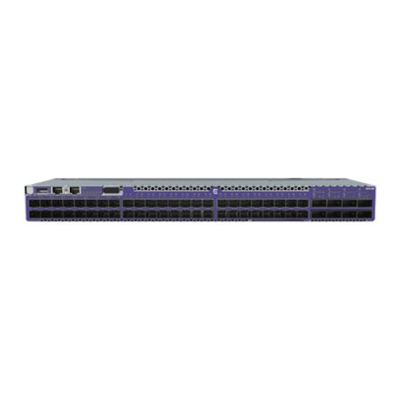
Two power supply bays located in the rear of the switch accommodate hot-swappable 750 W AC or DC power supplies that power the switch. The switch supports two AC or two DC power supplies, or one AC and one DC power supply. For more information about the power supplies used in the 8520 Series switches, see Power Supplies for Use with Your Switch on page 15. - Page 12 2 = Serial console port RJ-45 4 = System LEDs The rear panel of the switch includes: • 6 fan module slots • Grounding lug • 2 power supply slots Figure 2: 8520-48Y Series Rear Panel Extreme 8520 Series Hardware Installation Guide...
-
Page 13: 8520-48Xt Switch Features
Figure 3: 8520-48XT Series Front Panel 1 = 1/10GbE 10GBaseT RJ-45 3 = 10/100/1000BASE-T OOB 5 = Serial console port ports management port RJ-45 6 = System LEDs 2 = 40/100Gbe QSFP28 ports 4 = USB Type A port Extreme 8520 Series Hardware Installation Guide... - Page 14 The rear panel of the switch includes: • 6 fan module slots • Grounding lug • 2 power supply slots Figure 4: 8520-48XT Series Rear Panel 1 = Grounding lug 2 = Power supply slots 3 = Fan module slots Extreme 8520 Series Hardware Installation Guide...
-
Page 15: Power Supplies For Use With Your Switch
Power Supplies for Use with Your Switch Each 8520 Series switch runs with two replaceable internal power supply modules that provide all of the power needed for the switch to operate. You can remove one power supply module without interrupting the switch's operation. Supported power supply configurations include two 750 W AC power supply modules, two 750 W DC power supply modules, or one 750 W AC and one 750 W DC power supply module. -
Page 16: 750 W Ac Power Supply
Note AC power input cords are not provided with AC power supplies. You can order an appropriate cord from Extreme Networks or from your local supplier. The power cord must meet the requirements listed in Power Cord Requirements for AC-Powered Switches and AC Power Supplies on page 74. -
Page 17: Site Preparation
The physical installation site must meet the following requirements for a safe and successful installation: • Building and electrical code requirements • Environmental, safety, and thermal requirements for the equipment you plan to install • Equipment rack requirements 2. Evaluating and meeting cable requirements. Extreme 8520 Series Hardware Installation Guide... -
Page 18: Operating Environment Requirements
Site Preparation After examining your physical site and verifying that all environment requirements are met, evaluate and compare your existing cable plant with the requirements of the Extreme Networks equipment to determine if you need to install new cables. 3. Meeting power requirements. -
Page 19: Set Up The Wiring Closet
Consult an electrical contractor for commercial building and wiring specifications. Control the Temperature Extreme Networks equipment generates a significant amount of heat. It is essential that you provide a temperature-controlled environment for both performance and safety. Install the equipment only in a temperature- and humidity-controlled indoor area that is free of airborne materials that can conduct electricity. -
Page 20: Control The Humidity Level
Table 7 summarizes the behavior of ExtremeSwitching switches when they experience high operating temperatures. Safeguards are built into all Extreme Networks switches and power supply units to minimize the risk of fire. Table 7: Thermal Shutdown and Restart Behavior Switch Model(s) -
Page 21: Rack Specifications And Recommendations
Because building codes vary worldwide, consult an electrical contractor to ensure proper equipment grounding for your specific installation. Provide Adequate Space for the Rack Provide enough space in front of and behind the switch so that you can service it easily. Extreme 8520 Series Hardware Installation Guide... -
Page 22: Secure The Rack
Extra room on each side is optional. Warning Extreme Networks switches do not have a switch for turning power to the unit on and off. For systems using an AC power supply, power to the switch is disconnected by removing the wall plug from the electrical outlet. -
Page 23: Label Cables And Keep Accurate Records
Assign a unique block of sequential numbers to the group of cables that run between each pair of wiring closets. • Assign a unique identification number to each equipment rack. • Identify all wiring closets by labeling the front panel of your Extreme Networks equipment and other hardware. • Keep accurate and current cable identification records. •... - Page 24 Keep all ports and connectors free of dust. Figure 6: Properly Installed and Bundled Cable 1 = Ensure adequate slack and bend radius Handle Fiber Optic Cable Fiber optic cable must be handled carefully during installation. Extreme 8520 Series Hardware Installation Guide...
- Page 25 Table 8: Cable Distances and Types Standard Media Type MHz•km Maximum Distance Rating (Meters) 1000BASE-SX 50/125 µm multimode fiber (850nm optical window) 50/125 µm multimode fiber 62.5/125 µm multimode fiber 62.5/125 µm multimode fiber Extreme 8520 Series Hardware Installation Guide...
- Page 26 1000BASE-T Category 5 and higher UTP cable – 1 Proprietary to Extreme Networks. Connections between two Extreme Networks 1000BASE-LX interfaces that use 10/125 µm single-mode fiber can use a maximum distance of 10,000 meters. Extreme 8520 Series Hardware Installation Guide...
-
Page 27: Use Rj45 Connector Jackets
RF interference can cause degradation of signal quality, and, in an Ethernet network environment, can cause excessive collisions, loss of link status, or other physical layer problems that can lead to poor performance or loss of communication. Extreme 8520 Series Hardware Installation Guide... -
Page 28: Meet Power Requirements
Extreme Networks equipment. The web page provides specifications for power cords in each country so that you can purchase cords locally. Extreme 8520 Series Hardware Installation Guide... -
Page 29: Ups (Uninterruptible Power Supply) Requirements
VA = Volts x Amperes 3. Add the VA from all the pieces of equipment together to find the total VA requirement. To determine the minimum volt-amperage requirements for your UPS, add 30% to the total. Extreme 8520 Series Hardware Installation Guide... -
Page 30: Follow Applicable Industry Standards
UPS transfer time. UPS transition times vary between UPS models and implementations, but shorter transition times are preferred. For Extreme Networks stacking products, a UPS transition time of 20 milliseconds or less ensures optimum performance and minimizes service interruptions. -
Page 31: Install The Switch
Turn on the Extreme 9920 on page 45 Connect Network Interface Cables on page 46 Before you attempt to install or remove an Extreme Networks switch, read the precautions in Safety Considerations for Installation on page 31. Extreme Networks switches fit into standard 19-inch equipment racks. -
Page 32: What You Will Need For The Installation
ESD-preventive wrist strap for installing optional ports at the back of the switch. Attach the Switch to a Rack or Cabinet The 8520 Series switch can be attached to a standard 19-inch equipment rack, in either of the following ways: •... -
Page 33: Four-Post Rack Mount
4. Attach a mounting bracket to each side of the switch housing, using the screws provided. Ensure that the blue tab is close to the mounting ear and away from the switch. Figure 9: Attaching a Mounting Bracket to One Side of the Switch Housing Extreme 8520 Series Hardware Installation Guide... - Page 34 Figure 11: Attaching the Slider Assembly to the Rear Rack Post 6. Locate the intermediate rail inside each slider assembly and pull it out to its fullest extent. (It remains attached to the slider assembly.) Extreme 8520 Series Hardware Installation Guide...
- Page 35 7. Push the switch in until both mounting brackets engage with the sliding rails. Figure 13: Engaging the Mounting Brackets with the Rail Assemblies 8. Release the tabs on both slider assemblies, and carefully push the switch back until it is firmly in place. Extreme 8520 Series Hardware Installation Guide...
-
Page 36: Two-Post Rack Mount
The side of the switch has different sets of holes for attaching mounting brackets in either configuration. Brackets for a two-post mount are not included in the box with the switch. However, they can be ordered separately using part number XN-2P-RKMT299. Extreme 8520 Series Hardware Installation Guide... - Page 37 3. Secure the brackets to the rack posts using rack-mounting screws that are appropriate for the rack (not provided). If the switch comes with installed AC power supplies, skip to the topic: Turn on the Extreme 9920 page 45. Extreme 8520 Series Hardware Installation Guide...
-
Page 38: Install Optional Components
Extreme Optics website to determine the appropriate optics. The first and last ports of the 8520 Series uplinks are capable of breakouts (they are color coded differently too). • For 8520-48Y models, the 1st and last uplink ports are ports 49 and 56 •... -
Page 39: Install A 750 W Internal Ac Power Supply
2. Verify that the new power supply is right side up. 3. Verify that the new power supply's airflow direction (front-to-back or back-to-front) is compatible with the other installed power supply (if any) and with the installed fan modules. Extreme 8520 Series Hardware Installation Guide... - Page 40 EMI levels. 6. Connect the AC power cord. a. If necessary, slide the plastic cord retainer farther away from the back of the switch. b. Connect the AC power cord to the input connector. Extreme 8520 Series Hardware Installation Guide...
-
Page 41: Install A 750 W Internal Dc Power Supply
You can use up to a 30-Amp breaker. To install a 750 W DC power supply in a switch, perform the following tasks in the order listed: Extreme 8520 Series Hardware Installation Guide... - Page 42 To prepare the cable wires, follow these steps: Procedure 1. Strip 6 mm (0.25 inch) of insulation from one end on each cable wire if necessary. 2. Repeat step for the other cable wire. Extreme 8520 Series Hardware Installation Guide...
- Page 43 Be sure to disconnect the ground wire after you disconnect all power cables. Procedure 1. Verify that the DC circuit is de-energized. 2. Attach an ESD-preventive wrist strap to your bare wrist and connect the metal end to an appropriate ground point on the rack. Extreme 8520 Series Hardware Installation Guide...
- Page 44 Always make sure that the DC circuit is de-energized before connecting or disconnecting the DC power cables on the DC power supply. Caution Provide proper connection and strain relief on the DC power cables in accordance with all local and national electrical codes. Extreme 8520 Series Hardware Installation Guide...
-
Page 45: Turn On The Extreme 9920
An AC power cord is not included with the AC power supply. You can purchase AC power cords for use in the US and Canada from Extreme Networks or from your local supplier. The cord must mee the requirements listed in Power Cord Requirements for AC-Powered Switches and AC Power Supplies page 74. -
Page 46: Connect Network Interface Cables
5. Repeat the preceding steps for the remaining cables on this or other switches or I/O modules. 6. Dress and secure the cable bundle to provide appropriate strain relief and protection against bends and kinks. Extreme 8520 Series Hardware Installation Guide... -
Page 47: Activate And Verify The Switch
5. Open a terminal emulator application (such as HyperTerminal on a PC, or TERM, Tip, or Kermit in a LINUX environment), and configure the application as follows: • In a Windows environment: Parameter Value Bits per second 115200 Data bits Parity None Extreme 8520 Series Hardware Installation Guide... -
Page 48: Configure The Switch For Use
Root or Factory password will result in fabric downtime. for user - admin Changing password for admin Enter old password: Enter new password: Re-type new password: passwd: all authentication tokens updated successfully Extreme 8520 Series Hardware Installation Guide... - Page 49 (.), and the underscore (_) only. Passwords are case- sensitive, and they are not displayed when you enter them on the command line. For more information on passwords, refer to Extreme SLX-OS Security Configuration Guide for the 8520 Series device.
-
Page 50: Remove And Replace Components
• If the power supply module has a blue tab, the airflow is back-to-front. To replace one or both AC internal power supplies in an 8520 Series switch, follow the steps in Install a 750 W Internal AC Power Supply on page 39. -
Page 51: Remove The Device From The Rack
These procedures assume that you have attached the device to the rack as described in one of the following topics: • Four-Post Rack Mount on page 33 • Two-Post Rack Mount on page 36 Procedure 1. Disconnect the device from its power source or sources. 2. Remove all cables and transceivers. Extreme 8520 Series Hardware Installation Guide... - Page 52 Carefully slide the device out of the slider assembly and place it on a flat surface. You can leave the slider assemblies in place. If you want to remove them, continue with the next step. Extreme 8520 Series Hardware Installation Guide...
- Page 53 Tilt the device so that the brackets are clear of the rack posts, and carefully lift it out of the rack. If the device cannot be tilted (because other equipment is mounted directly above and below), remove one or two mounting brackets from the device and then slide the device out. Extreme 8520 Series Hardware Installation Guide...
- Page 54 Remove the Device from the Rack Remove and Replace Components Results As a best practice, if you plan to use the device again later, store it with the mounting brackets attached. Extreme 8520 Series Hardware Installation Guide...
-
Page 55: Monitor The Switch
No power; some power rails are dropping below specification Green Valid power. All monitored voltages are nominal. System Boot failed. Green Operationl. Blinking amber Booting. Amber Fault. Fan Status No power. Green Fan is operational. Amber Fan failure. Extreme 8520 Series Hardware Installation Guide... -
Page 56: Management Port Leds
The port has link established. There is no data activity. Blinking green The port has link established and there is data activity. Blinking slowly green The port is disabled by the admin. Amber Fault. Extreme 8520 Series Hardware Installation Guide... -
Page 57: Sfp+/Sfp28 Port Leds For The 8520-48Y
100 Gb or 40 Gb 1st LED No link. Link is active, but there is no activity. Blinking Link is active and there is activity. All LEDs blinking (on 1 Switch is beaconing. second, off 1 second) Extreme 8520 Series Hardware Installation Guide... -
Page 58: 750 W Ac Power Supply Leds
AC input OK (Green) Good AC input fail 750 W DC Power Supply LEDs The following table describes the meanings of the LEDs on the 750 W DC power supply (part number XN-DCPWR-750W-F or XN-DCPWR-750W-R). Extreme 8520 Series Hardware Installation Guide... - Page 59 (Solid) No PSU fault OUT OK DC output DC output OK (Green) Good (solid) Off or DC output fail Blinking IN OK DC input DC input OK (Green) Good "IN OK" DC input fail Extreme 8520 Series Hardware Installation Guide...
-
Page 60: Technical Specifications
750 W Power Supplies Technical Specifications on page 72 Power Cord Requirements for AC-Powered Switches and AC Power Supplies on page 74 Console Connector Pinouts on page 75 The 8520 Series includes the following switch models: • 8520-48Y-8C • 8520-48Y-8C-AC-F •... -
Page 61: Software Specifications
Technical Specifications Software Specifications Software Specifications The following table includes software specifications for the 8520 Series switches. Software Specifications Description Maximum MAC addresses 64,000 Maximum VLANs 4,096 Maximum ACLs (IPv4/IPv6/L2) 2,000 Maximum members in a standard LAG Maximum number of MCT switches... -
Page 62: Weights And Physical Dimensions
Weights and Physical Dimensions Technical Specifications Weights and Physical Dimensions The following tables include the unpackaged and packaged weights and dimensions of the 8520 Series switches. Table 16: 8520 Series Unpackaged Dimensions 8520-48Y Height: 4.3 cm (1.7 in) Width: 44.0 cm (17.3 in) Length: 54.15 cm (21.32 in) -
Page 63: Acoustic Specifications
Four-post rack mount kit (included with switch) 2.94 kg (6.48 lb) Two-post rack mount kit (separately orderable) .51 kg (1.12 lb) Acoustic Specifications The following table includes acoustic specifications of the 8520 Series switches. Switch Model Bystander Sound Pressure (at Declared Sound Power (at 25°C) 25°C) -
Page 64: Power Consumption
Red = Front-to-Back • Blue = Back-to-Front Power Consumption The following tables include power consumption information for the 8520 Series switches. 8520-48Y The following tables provide AC and DC power consumption information for the 8520-48Y switch models. Table 21: AC IN: 220V... - Page 65 Notes Dual Power Single Power PSU1 PSU2 Empty 1. No fiber transceivers inserted Model 2. No port up link 3. 85% fan duty Standby 1. All ports up link Model 2. 85% fan duty Extreme 8520 Series Hardware Installation Guide...
-
Page 66: 8520-48Xt
Single Power PSU1 PSU2 Empty 148.5 275.5 1. No fiber transceivers inserted Model 2. No port up link 3. 85% fan duty Standby 155.8 1. All ports up link Model 2. 85% fan duty Extreme 8520 Series Hardware Installation Guide... - Page 67 Notes Dual Power Single Power PSU1 PSU2 Empty 1. No fiber transceivers inserted Model 2. No port up link 3. 85% fan duty Standby 1. All ports up link Model 2. 85% fan duty Extreme 8520 Series Hardware Installation Guide...
-
Page 68: Power And Heat Dissipation
1. Snake test with 100% traffic load Model (64 byte packet length) 2. 100% fan duty Power and Heat Dissipation The following table includes power and heat dissipation information for the 8520 Series switches. Switch Model Minimum Heat Minimum Power Maximum Heat... -
Page 69: Cpu, Memory Specifications
187,308 @ 50°C 8520-48XT-6C-DC-R 421,461 hrs @ 25°C 176,926 @ 45°C CPU, Memory Specifications The following table includes cpu and memory specifications for the 8520 Series switches. Specifications 2.2 GHz 8-core CPU 16 Gb DDR4 ECC memory 128 Gb SSD memory... -
Page 70: Standards
EN 55024:2010/A1:2015 EN 55011:2009+A1:2010 (Group 1, Class A), EN 55035 EN 61000-6-2:2005+AC:2005 EN 61000-6-4:2007+A1:2011 EN 61000-3-2:2014 Class A EN 61000-3-3:2013 EN 61000-4-2:2009 EN 61000-4-3:2006+A1:2008+A2:2010 EN 61000-4-4:2012 EN 61000-4-5:2014 EN 61000-4-6:2014/AC:2015 EN 61000-4-8:2010 EN 61000-4-11:2004/A1:2017 Extreme 8520 Series Hardware Installation Guide... - Page 71 EN/ETSI 300 019 (Environmental for Telecommunications) MEF9 and MEF14 certified for EPL, EVPL, and ELAN Table 30: IEEE 802.3 Media Access Standards IEEE 802.3ab 1000BASE-T IEEE 802.3z 1000BASE-X IEEE 802.3ae 10GBASE-X IEEE 802.3ba 40GBASE-X Extreme 8520 Series Hardware Installation Guide...
-
Page 72: Environmental Data
14 drops minimum on sides and corners at 42 in (<15 kg box) 750 W Power Supplies Technical Specifications Four 750 W power supply units are available for use with the 8520 Series switches: • 750W AC power supply - front-to-back airflow (part no. XN-ACPWR-750W-F) •... - Page 73 Total output power not to exceed 750W Power supply input socket IEC 320 C14 Power cord input plug IEC 320 C13 Power cord wall plug Refer to Power Cord Requirements for AC-Powered Switches and AC Power Supplies on page 74 Extreme 8520 Series Hardware Installation Guide...
-
Page 74: Power Cord Requirements For Ac-Powered Switches And Ac Power Supplies
For cords up to 6 feet (2 m) long, the wire size must be 18 AWG (.75 mm ) minimum; over 6 feet, the minimum wire size is 16 AWG (1.0 mm For details about obtaining AC power cords for use in your country, refer to http:// www.extremenetworks.com/product/powercords/. Extreme 8520 Series Hardware Installation Guide... -
Page 75: Console Connector Pinouts
CTS (clear to send) Figure 24 shows the pinouts for a 9-pin to 25-pin (RS-232) null-modem cable. Figure 24: Null-Modem Cable Pinouts Figure 25 shows the pinouts for a 9-pin to 9-pin (PC-AT) null-modem serial cable. Extreme 8520 Series Hardware Installation Guide... - Page 76 RJ45-to-DB-9 adapter. Table 40: Pinouts for an RJ45 to DB-9 Adapter Signal RJ45 Pin DB-9 Pin CTS (clear to send) DTR (data carrier detect) TXD (transmit data) GND (ground) GND (ground) RXD (receive data) Extreme 8520 Series Hardware Installation Guide...
- Page 77 Technical Specifications Console Connector Pinouts Table 40: Pinouts for an RJ45 to DB-9 Adapter (continued) Signal RJ45 Pin DB-9 Pin DSR (data set ready) RTS (request to send) Extreme 8520 Series Hardware Installation Guide...
-
Page 78: Safety Information
• Racks for Extreme Networks equipment must be permanently attached to the floor. Failure to stabilize the rack can cause the rack to tip over when the equipment is removed for servicing. Extreme 8520 Series Hardware Installation Guide... -
Page 79: General Safety Precautions
This system contains no customer serviceable components. Do not attempt to repair a chassis, power supply, module, or other component. In the event of failure, return the defective unit to Extreme Networks for repair or replacement, unless otherwise instructed by an Extreme Networks representative. -
Page 80: Fiber Optic Ports And Optical Safety
Install all cables in a manner that avoids strain. Use tie wraps or other strain relief devices. Fiber Optic Ports and Optical Safety The following safety warnings apply to all optical devices used in Extreme Networks equipment that are removable or directly installed in an I/O module or chassis system. -
Page 81: Install Power Supply Units And Connect Power
For the ratings and power input requirements of each power supply unit, see "Technical Specifications" or the data sheet for the power supply at www.extremenetworks.com. Warning Be sure to satisfy the requirements listed in this section when you install Extreme Networks power supplies or connect power. When you install any power supply: •... -
Page 82: Select Power Supply Cords
When you install DC power supplies or connect DC power: • Extreme Networks DC power supplies do not have switches for turning the unit on and off. Make sure that the DC circuit is de-energized before connecting or disconnecting the DC power cord at the DC input power socket. -
Page 83: Battery Notice
Il y a risque d’explosion si la pile est remplacée par un type de pile incorrect. Éliminez les piles usées en conformité aux règlements locaux d'élimination des piles. Battery Warning - Taiwan About This Task Extreme 8520 Series Hardware Installation Guide... -
Page 84: Regulatory Information
Electromagnetic Compatibility (EMC) Directive 2014/30/EU • Low Voltage Directive (LVD) 2014/35/EU • EN 55032/EN 55024 (European Immunity Requirements) ◦ EN61000-3-2/JEIDA (European and Japanese Harmonics Spec) ◦ EN61000-3-3 EMC Warnings Taiwan BSMI Warning China CCC Warning Extreme 8520 Series Hardware Installation Guide... -
Page 85: China And Taiwan: Restriction Of Hazardous Substances (Rohs)
This Class A digital apparatus meets all requirements of the Canadian Interference-Causing Equipment Regulations, ICES-003 Class A. Cet appareil numérique de la classe A est conforme à la norme NMB-003 du Canada. China CCC statement Extreme 8520 Series Hardware Installation Guide... -
Page 86: Australia (Rcm)
Class A device (Broadcasting Communication Device for Office Use): This device obtained EMC registration for office use (Class A), and may be used in places other than home. Sellers and/or users need to take note of this. Extreme 8520 Series Hardware Installation Guide... -
Page 87: Japan (Vcci Class A)
Japan power cord English translation of above statement ATTENTION: Never use the power cord packed with your equipment for other products. Extreme 8520 Series Hardware Installation Guide... -
Page 88: Index
UPS 29 8520 Series 10 announcements 8, 9 on switch 75 ANSI standards 30 conventions notice icons 6 text 6 cooling back-to-front cooling 50 8520 Series 11 battery notice 83 cords bend radius 23, 24 requirements 74 BICSI 22 selecting 82 brackets, for mounting in rack 51 building codes 18 Extreme 8520 Series Hardware Installation Guide... - Page 89 LEDs system protection 20 750 W AC power supply 58 750 W DC power supply 58 8520 Series switches 55 logging in to the switch 48 airflow 50 replacing 50 features management port 8520 Series switches 10 8520 Series 10 feedback 8...
- Page 90 RFI, see radio frequency interference (RFI) optical transceivers RJ45 cable 27 installing 38 optional components installing 38 overview safety 8520 Series switches 10 precautions when installing 31 requirements 78 service access to the rack 21 signal quality 27 pinouts site planning 17 DB-9 console connector 75 site preparation 32 null-modem cable 75 slack in cable 23...
- Page 91 Index UTP cable bend radius 23 category 5 23 discharge ESD 23 preventing RFI 27 VOSS initial login 48 warnings 6 wire connecting 43 wiring closet electrostatic discharge (ESD) 20 floor coverings 19 grounding 19 humidity 20 rack, securing 22 temperature 19 wiring terminals 21...
Need help?
Do you have a question about the 8520 Series and is the answer not in the manual?
Questions and answers