Table of Contents
Advertisement
Advertisement
Table of Contents
Troubleshooting

Related Manuals for Tally Dascom 7006


Summary of Contents for Tally Dascom 7006
- Page 1 User Guide 7006 7008 Thermal Printer...
-
Page 3: Table Of Contents
T a b l e o f C o n t e n t s Table of Contents Welcome ..........1-1 Getting Started . - Page 4 T a b l e o f C o n t e n t s Windows Driver Installation ........3-2 Setting Printing Preferences .
- Page 5 T a b l e o f C o n t e n t s Printing Standard Labels and Tags ......7-1 Using CPL Programming .
- Page 6 T a b l e o f C o n t e n t s Printer Specifications ........9-1 Technical Specification Information .
- Page 7 T a b l e o f C o n t e n t s Cleaning and Preventive Maintenance ....11-1 Cleaning Instructions ........11-1 Printhead Assembly Removal and Replacement .
-
Page 9: Welcome
Congratulations on the purchase of this thermal label printer. With its 2-year warranty, mid-range performance, and customer service, the printer will provide you continuous label printing with very little downtime and at the highest quality. Tally Dascom is com- mitted to providing a high-performance and reliable user experience. This User’s Manual provides information on how to install the printer and includes all necessary user support information. - Page 10 W e l c o m e Technical Support — For technical support please contact your dealer or the Technical Support Team of your Tally Dascom Representatives – see last page of this manual.
-
Page 11: Getting Started
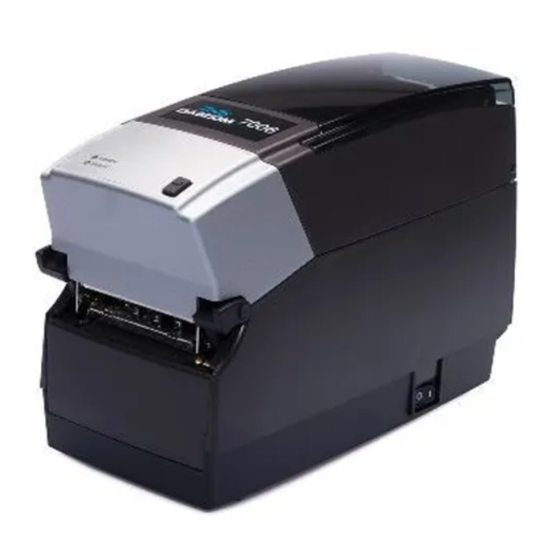
Chapter Getting Started First, take a tour around the printer to understand its parts and functions. Parts and Functions Outside the Printer Figure 2-1: Top and Front View Device A – CD control panel (7008 only) Back-lit, two-line, 16-character display with full menus to change setup options B –... - Page 12 G e t t i n g S t a r t e d Device C – READY LED Shows printer status GREEN – Printer ready to accept data RED – Printer error, empty media roll, or paused operation dur- ing batch mode processing D –...
-
Page 13: Inside The Printer
G e t t i n g S t a r t e d Inside the Printer Figure 2-2: Side View Device A – Large roll spindle slot Holds large roll media B – Standard roll spindle slot Holds standard roll media C –... -
Page 14: Paper Media Guide Bar
G e t t i n g S t a r t e d Paper Media Guide Bar Figure 2-3: Inner Side View of Media Bar Figure 2-4: Top View of Media Guide from Behind Printer Device A – Media guide (silver bar) Guides the labels through the printer... -
Page 15: Connection Ports And Power Connector
G e t t i n g S t a r t e d Connection Ports and Power Connector Figure 2-5: Connections Ports and Power Connector (Back View) Connector A – ON/OFF switch Controls printer power B – Power connector Connects to power supply C –... -
Page 16: Take Up Spindle And Take Up Clutch (Gears)
G e t t i n g S t a r t e d Take Up Spindle and Take Up Clutch (Gears) Figure 2-6: Take Up Spindle, Clutch, and Side view of Clutch Gears Components Description Take Up Spindle Take Up Clutch Supply Spindle and Supply Clutch Figure 2-7: Supply Spindle and Clutch Components... -
Page 17: Index
G e t t i n g S t a r t e d Printhead Assembly (TPH, Shield, Bracket, and LED Array) Figure 2-8: Printhead Assembly Platen and Index Sensor Figure 2-9: Platen Assembly and Index Sensor Components Description Index Sensor Platen... -
Page 18: Understanding The Control Panel Buttons And The Lcd (7008 Only)
(7008 Only) When the printer is powered on, the LCD displays “Tally Dascom 7008”. After approxi- mately 2 seconds, the LCD displays “Tally Dascom”. This is an indication that the menu is at its highest level. From this menu level, the LEFT button displays the current status of the printer; either a READY condition, or the most recent error encountered. - Page 19 G e t t i n g S t a r t e d LEFT button (B): Press the LEFT button to display the current printer status. From within the menu, pressing the LEFT button returns to the previous menu level. UP (A) and DOWN (C) buttons: Allows menu navigation up and down through the menu tree, and allows the user to increase or decrease numeric values in some menu items.
-
Page 20: Understanding The Lcd Menu Structure
G e t t i n g S t a r t e d Understanding the LCD Menu Structure MAIN MENU USER MENU Contrast 0 … 8 Contrast Backlight ON or OFF Control Keyboard English, French Layout Beeper Volume 0 … 3 Volume Set Date Date (MM/DD/YY) - Page 21 Yes? Or No? Factory Defaults Yes? Or No? CUSTOMER For technical support please contact your dealer or the Technical Support SUPPORT Team of your Tally Dascom Representatives – see last page of this manual. Web: http://jadmin.dascom.com RETURN Return to Main Menu 2-11...
-
Page 22: Setting Up The Printer
G e t t i n g S t a r t e d Setting Up the Printer Setting up the printer is an easy process. This chapter describes printer requirements, printer controls, loading thermal transfer ribbon, and loading print media. The printer self test is also described. -
Page 23: Unpacking The Printer
G e t t i n g S t a r t e d Unpacking the Printer Printer Accessories Power cord Power supply Figure 2-11: Packaging Diagram 2-13... -
Page 24: Controls, Indicators, And Connectors
G e t t i n g S t a r t e d Controls, Indicators, and Connectors Controls and indicators for the printer are located on the front panel and right side of the printer. 7008 printers also have an LCD display on the user interface. Figure 2-12: Printer Controls and Indicators Device Primary Function... -
Page 25: Connecting Data Cables To The Printer
Ethernet cable USB cable (compatible with both USB-A and USB-B) Tally Dascom custom parallel cable Tally Dascom custom serial cable or serial adapter cable Figure 2-13: (Back View) Connections and Power Connector A – ON/OFF switch Controls printer power B –... -
Page 26: Usb-A Host Connectivity
G e t t i n g S t a r t e d USB-A HOST Connectivity The printer supports hubs, USB keyboards, USB keyboard wedge scanners, and USB flash drives. These devices can be used to input data directly to the printer. They are most commonly used in conjunction with CPL scripting language, for example, menus and stored formats, to produce labels. -
Page 27: Connecting Power To The Printer
G e t t i n g S t a r t e d Connecting Power to the Printer The next step is to provide power to the printer. Use only the AC adapter supplied with the printer. Using a power adapter not certified for use is both unsafe and voids the war- ranty on the printer. - Page 28 G e t t i n g S t a r t e d 2. Connect the power supply cord into the power connector located in the back corner of the printer. The flat end of the power supply cord, listed as B below in Figure 2-15, has an arrow to indicate which end is on top.
- Page 29 G e t t i n g S t a r t e d 3. Connect the power cord into the power source by carefully plugging the power cord into the wall outlet or other power source. NOTE: Once the power supply is plugged into the wall, the green LED illumi- nates on the power supply unit.
-
Page 30: Printer Power Test
G e t t i n g S t a r t e d Printer Power Test The power supply indicates power with a green light. The next step verifies the printer is receiving power. 4. Press the power switch (D in Figure 2-17 below) to the ON position. NOTE: The power light on the top user interface cover turns green to indicate the unit is receiving power. - Page 31 NOTE: (7008 printers only) the LCD briefly displays PRESS RIGHT ARROW FOR MENU. Then the LCD displays “Tally Dascom 7008” for about one second. When the printer is ready to print, the LCD displays “Tally Dascom” (see Figure 2-18 below).
-
Page 32: Thermal Transfer Ribbon Loading (Tt Printers Only)
G e t t i n g S t a r t e d Thermal Transfer Ribbon Loading (TT Printers Only) To run the printer in thermal transfer mode, a ribbon must be loaded properly into the printer in order to print. This section details step-by-step instructions on how to load thermal transfer ribbon into the printer. - Page 33 G e t t i n g S t a r t e d 2. Remove the Test Sample from inside the printer, and store it with other documenta- tion for future reference. Figure 2-21: Removing the Test Sample from the Printer 3.
- Page 34 G e t t i n g S t a r t e d 4. Once the tape is removed, discard the tape, and spread the ribbon out so the text on the leader A is facing down. Make sure the ribbon does not roll off the table when setting it down.
- Page 35 G e t t i n g S t a r t e d 6. Next, raise the printhead mechanism fully. Refer to the figure below. Figure 2-25: Fully Raised Printhead Mechanism CLEANING NOTE: This is the ideal position for cleaning the printhead, printhead shield, and platen.
- Page 36 G e t t i n g S t a r t e d 7. Next, insert the ribbon supply roll. Lift the ribbon supply roll, as shown in Figure 2-26, with one hand as it currently is positioned with the leader text showing. Examine the ends of the ribbon supply roll and notice the notches on the roll.
- Page 37 G e t t i n g S t a r t e d 8. While holding the ribbon in place, pull gently on the green supply spindle to insert the ribbon supply roll into place. Figure 2-28: Pulling Out the Ribbon Supply Spindle 9.
- Page 38 G e t t i n g S t a r t e d 10. When the ribbon feels secure, gently push and rotate the green supply spindle clock- wise, while holding the supply clutch hug, until the ribbon seats properly. Figure 2-30: Supply spindle Rotation to Secure Supply Roll In Place 11.
- Page 39 G e t t i n g S t a r t e d NOTE: If the printhead mechanism latches, a clicking noise will sound. If the printhead mechanism is latched by mistake, push up the black printhead latches to release the printhead mechanism as shown in Figure 2-24. 12.
- Page 40 G e t t i n g S t a r t e d 13. Pull gently on the green take up spindle to insert the ribbon take up roll into place. Line up the notches on the ribbon take up core with the printer take up spindle notches to secure the take up roll into place.
- Page 41 G e t t i n g S t a r t e d 15. Once the ribbon take up core has been installed, turn the take up spindle clockwise to wind the ribbon leader onto the take up core. Rotate the green take up spindle clockwise until the black ribbon begins winding on the take up core as shown in Figure 2-35.
-
Page 42: Loading Media
G e t t i n g S t a r t e d Loading Media All printers have media loading instruction labels on the bottom of the dust cover. To increase the life of the printhead, we recommend using media approved by the manu- facturer with all printer models. - Page 43 G e t t i n g S t a r t e d 3. Insert the spindle into the approved sample media roll (see inward and outward wound media figures below). Figure 2-39: Inserting the Spindle Into the Approved Inward Wound Media Figure 2-40: Inserting the Spindle into Outward Wound Media NOTE: For more information regarding approved media please contact a local reseller or the manufacturer.
- Page 44 G e t t i n g S t a r t e d 4. Prior to loading media, take a moment to review operation of the media guides. The guides are spring loaded in order to provide proper media control during printing. The right media guide has a green locking tab as shown in Figure 2-41, that holds the guides in any position.
- Page 45 G e t t i n g S t a r t e d 5. To initially set the media guides to the proper setting, try to push either guide to the outside of the printer. If the guide does not move, lift up slightly on the green lock until it stops in the upright position.
- Page 46 G e t t i n g S t a r t e d 7. Unroll a few labels. Position the media, print side up, into the printer as shown in Figure 2-44 and 2-45. Figure 2-44: Media Print Side Must be Facing Up for Inward Wound Media Figure 2-45: Media Print Side Must be Facing Up for Outward Wound Media 2-36...
- Page 47 G e t t i n g S t a r t e d 8. Place the media under the media guide bar as shown in Figure 2-46. Figure 2-46: Place the Media Under the Media Guide Bar 9. Lower the media between the two media guides. Position the media as shown in Fig- ure 2-47.
- Page 48 G e t t i n g S t a r t e d 10. Once the guides are against the sides of the roll, push the roll down in the slot as shown in Figure 2-48. This locks the media guide in the proper position. The media should look as shown.
- Page 49 G e t t i n g S t a r t e d 12. The media should be visible as shown in Figure 2-50 below the round metal rod. Figure 2-50: Front View of Media Being Loaded Under Media Guide 13.
- Page 50 G e t t i n g S t a r t e d 14. Once the media is pulled forward three to four inches, latch the mechanism as shown in Figure 2-52. Figure 2-52: Latching the Mechanism 15. Close the dust cover to enclose standard size media while printing. Figure 2-53: Closed Dust Cover 2-40...
-
Page 51: Loading Large Roll Od Media
G e t t i n g S t a r t e d Loading Large Roll OD Media 1. Locate the rear door screws at the rear of the printer as identified with the arrows in Figure 2-54. Remove the screws with a #2 Phillips screwdriver. Keep the screws for future usage. - Page 52 G e t t i n g S t a r t e d 3. Open the media covers as shown in Figure 2-56. Figure 2-56: Loading Large Media Roll, Print Side Up Figure 2-57: Large Media Roll in Position 2-42...
- Page 53 G e t t i n g S t a r t e d 4. Close the top cover and let the dust cover rest on the large media roll. Figure 2-58: Closing the Top Cover 2-43...
-
Page 54: Performing The Self Test
G e t t i n g S t a r t e d Performing the Self Test The self test checks the printer’s overall operability, and lists the printer’s current set- tings. Refer to the figures and instructions below to perform the printer self test. Figure 2-59: Performing the Printer Self Test IMPORTANT! The printer should be loaded with media, connected to AC power, and turned on. - Page 55 G e t t i n g S t a r t e d The output from the self test is described in the table below. Example (Actual settings may Setting Description vary from examples listed below) Firmware version and date FW: 195-170-149 V1.49 Printer serial number S/N: P012345678...
- Page 56 G e t t i n g S t a r t e d Pitch (dots) Print density in dots per inch Pitch (dots): 200 Present Label When ON, Printer will advance and reverse Present Label: ON the distance specified below for each label printed.
-
Page 57: Software Installation
Chapter Software Installation For all models there are two methods to install the required software. METHOD A: Install Software Using the Installation CD Place the Installation CD into the computer and the CD automatically runs through all the required steps to properly install the required software for the printer. When the installation is complete, proceed to Chapter 4 of this User’s Guide. -
Page 58: Windows Driver Installation
S o f t w a r e I n s t a l l a t i o n Windows Driver Installation NOTE: Please ensure to install the drivers BEFORE connecting the printers to the PC. 1. Browse to the drivers directory: [Drive]:\Users\<logon_name>\TallyDas- com\Drivers 2. -
Page 59: Installing And Running The Administrator Software
S o f t w a r e I n s t a l l a t i o n Installing and Running the Administrator Software The Administrator configuration software allows the user to configure, test, and operate the printer. Installing the Administrator Configuration Software 1. -
Page 61: Using The Administrator Tool
Chapter Using the Administrator Tool Select the connection method being used between computer and printer. If using serial, select the appropriate communication port and baud rate. The default serial baud rate is 9600. If using USB, select the appropriate printer driver. NOTE: Refer to Chapter 3, “Windows Driver Installation”... -
Page 62: Administrator Sections
U s i n g t h e A d m i n i s t r a t o r T o o l If using Parallel, select the appropriate LPT port If using Network, select the correct IP address. NOTE: Refer to Chapter 6 “Network Printing”... -
Page 63: Method 1: Calibrate Using The Administrator Configuration Software
U s i n g t h e A d m i n i s t r a t o r T o o l Method 1: Calibrate using the Administrator configuration software Once properly installed as shown in Chapter 3 “Installing and Running the Administra- tor Software”, calibration may be performed using the Index Setting field in the Printer Settings tab of Administrator. -
Page 64: Fonts/Objects
U s i n g t h e A d m i n i s t r a t o r T o o l Fonts/Objects View the printer’s fonts, stored objects and graphics. Delete and loading objects is also available with this setting. -
Page 65: Pcl Windowing
U s i n g t h e A d m i n i s t r a t o r T o o l PCL Windowing This tab is useful only for PCL-equipped printers (4 inch 300 dpi printers). It allows you to make a label out of a full-page PCL document by specifying the small region of that document you wish to print. -
Page 66: Cpl Editor
U s i n g t h e A d m i n i s t r a t o r T o o l CPL Editor The CPL editor is a text editor/terminal program for communicating with the printer. This editor allows the user to create, open or save text files, and send them to the printer. -
Page 67: Usb A Host
Chapter USB A Host Loading Firmware Using a USB Flash Drive When a USB flash drive is inserted into the USB A port (referred to as “E” below in Figure 5-1), the printer looks at the content of the flash drive, following a set of rules, and deter- mines if the drive contains a firmware upgrade. -
Page 68: Loading Firmware Using The Usb A Host
U S B A H o s t Loading firmware using the USB A Host 1. Create a folder on the flash drive at the root level named TallyDascom. 2. Inside this folder create a folder named Firmware. 3. Copy the firmware file (obtained, for example, from the manufacturers web site) in the Firmware folder. -
Page 69: Network Printing
Chapter Network Printing Network-enabled printers can be connected directly to a network, providing the flexibility of printing to the same printer from multiple workstations. To configure the printer’s network settings, connect to the Administrator program over a local USB or serial or parallel port. Refer to Chapter 4 “Using the Administrator Tool” for instructions on connecting to the printer using a local port. -
Page 70: Using Automatic Address Assignment
N e t w o r k P r i n t i n g The screen should look like this: Using Automatic Address Assignment Automatic address assignment, known as DHCP configuration, is only possible if the net- work being used supports it. If the network does support DHCP, put the printer into DHCP mode by selecting the DHCP checkbox under the address fields in the Ethernet Settings area. -
Page 71: Verifying Network Settings
N e t w o r k P r i n t i n g Verifying Network Settings When a static address was assigned or configured for DHCP, after clicking the Apply button, disconnect the Administrator from the printer, power-cycle the printer, and then connect to it once again using the USB, serial, or parallel port. -
Page 72: Configuring A Printer Driver For Network Use
N e t w o r k P r i n t i n g Configuring a Printer Driver for Network Use In order to print using the driver, a new port must be configured within the printer driver. 1. Locate the appropriate driver in the Windows Printers folder. 2. - Page 73 N e t w o r k P r i n t i n g 7. In the Printer Name or IP Address box, enter the IP address assigned to the printer. The Port Name box is auto-populated. Click Next. 8.
-
Page 74: Sharing The Printer On A Network
N e t w o r k P r i n t i n g Sharing the Printer on a Network ASSUMPTION: It is assumed that the printer is connected to a local machine already on a network. 1. Locate the appropriate Driver in the Windows Printers folder. 2. -
Page 75: Printing Standard Labels And Tags
Chapter Printing Standard Labels and Tags Sources for printed label and tag data include the following: Label software CPL programming Third party applications or interfaces Using CPL Programming A common method of printing labels is CPL programming. Commands and data are sent to the printer using the Administrator. - Page 76 P r i n t i n g S t a n d a r d L a b e l s a n d T a g s To save this label format for future use, click the Save to File button. To reload it, or any other label format, click the Open File button.
-
Page 77: Using Third-Party And Proprietary Applications
P r i n t i n g S t a n d a r d L a b e l s a n d T a g s Using Third-Party and Proprietary Applications Labels are frequently printed from commercial software or proprietary applications. Printing from Microsoft Word The instructions below describe how to create both simple and complex labels using Microsoft Word software. - Page 78 P r i n t i n g S t a n d a r d L a b e l s a n d T a g s 3. Select a printer. 4. Click Close to close the Print dialog box.
-
Page 79: Setting Label Size
P r i n t i n g S t a n d a r d L a b e l s a n d T a g s Setting Label Size Set up the Word document for the desired label size. 1. - Page 80 P r i n t i n g S t a n d a r d L a b e l s a n d T a g s 3. Click the Paper tab. 4. Set the correct width and height for the label. The example shows a 2.4” wide by 1” tall label.
- Page 81 P r i n t i n g S t a n d a r d L a b e l s a n d T a g s 5. Click OK and, if necessary, Fix to reset the margins. The Word document should look similar to the figure below.
-
Page 82: Creating A Label And Barcode
P r i n t i n g S t a n d a r d L a b e l s a n d T a g s Creating a Label and Barcode Design the label in a Word document. Use the following steps to design a barcode. 1. -
Page 83: Printing From Proprietary Applications
P r i n t i n g S t a n d a r d L a b e l s a n d T a g s Printing from Proprietary Applications There are a variety of applications that are industry or function specific. Some of these require a generic text printer driver. -
Page 85: Troubleshooting
Chapter Troubleshooting The printer requires minimal user maintenance. When problems do occur, however, it is important to isolate the root cause between hardware or programming issues. Isolating Problems Programming issues can often make problems appear hardware related. Use the follow- ing steps to determine the source of the problem. -
Page 86: Print A New Label Format
T r o u b l e s h o o t i n g Print a New Label Format If a known printable format is unavailable then a new format may be created using an available text editor. Creating and sending the simple format listed below should help isolate the problem. -
Page 87: Common Issues
T r o u b l e s h o o t i n g Common Issues The following issues are based on technical support records of user questions. Labels Skipping or Printer Feeding Blank Labels Label skipping can frequently be corrected by performing a printer calibration. Refer to the calibration section of Chapter 4 (“Calibrating the Printer”). -
Page 88: Serial Communication
T r o u b l e s h o o t i n g Send this file to the printer by selecting File then selecting Print. The printer will not print anything but the ready light will blink on and off. Once a solid Green ready light is visible, cycle the power to the printer. -
Page 89: Printing Too Light
T r o u b l e s h o o t i n g Printing Too Light Download and install the Administrator configuration software for simplified setting of these values from the Installation CD included with the printer or from the manufactur- ers web site. -
Page 90: Paper Is Jammed In The Printer
T r o u b l e s h o o t i n g Paper is Jammed in the Printer Turn the printer off before attempting to un-jam the printer. If a label is jammed in the printer, unplug the printer from its power source and remove the jammed label by hand only. -
Page 91: Printer Specifications
Chapter Printer Specifications Specifications are provided for reference and are based on printer tests using Tally Das- com brand ribbons and labels. Results may vary in actual application settings or when using products other than recommended supplies. We recommend always qualifying any application with thorough testing. -
Page 92: Optional Features
300 dpi Print Resolution (12 dots/mm) Ethernet 10/100 Base-T interface Thermal Transfer Printing PCL (4” printers with 300 dpi printhead only) Printing Specifications Nominal 2” 7006 or 7008 4” 7006 or 7008 Printer Size Print 203 dpi Standard 300 dpi Optional... -
Page 93: Media Specifications
P r i n t e r S p e c i f i c a t i o n s Media Specifications Media Types: Direct thermal or thermal transfer labels, tags, wristbands, static labels, and receipt paper. Media Thickness: 0.010” (0,25mm) thickness max. Index types: Reflective and transmissive sensors to detect gaps between labels, die-cuts, black-marks, notches, and holes. -
Page 94: Ribbon Specifications
P r i n t e r S p e c i f i c a t i o n s Ribbon Specifications Ribbon width: 2” Printer: 2.4" (61mm) Max. 2” Nominal Length: 6500” (approx. 165m) Max. 4” Printer: 4.25" (108mm) Max. 4”... -
Page 95: Bar Code Symbologies And Specifications
P r i n t e r S p e c i f i c a t i o n s Bar Code Symbologies and Specifications UPCA ADD 2 EAN 8 128C UPCE ADD 5 EAN 13 CODE128 UPCE1 CODE 39 PLESSEY EAN128 POSTNET... -
Page 96: Communications Specifications
P r i n t e r S p e c i f i c a t i o n s Communications Specifications Parallel Interface: Centronics compatible parallel interface (requires a special cable). High-speed serial interfaces: Serial RS-232 (requires a special cable) Configurable baud rate (1,200 –... -
Page 97: Physical Specifications
5” (127mm) 6.9” (175mm) Depth 10.04” (255mm) 10.04” (255mm) DT Weight 5.02 lbs (7008) 4.91 lbs (7006) 5.91 lbs (7008) 5.88 lbs (7006) TT Weight 5.23 lbs (7008) 5.00 lbs (7006) 6.10 lbs (7008) 6.00 lbs (7006) Software Administrator: Printer with USB/Serial bi-directional configuration software, included with printer requires Windows driver installation. -
Page 99: Consumables
Chapter Consumables Compatible Media The manufacturer stocks a wide variety of labels and tags for use in thermal printers. Items range from paper labels and tags in various sizes and synthetic jewelry labels to RFID labels and hospital wristbands. If the standard items will not fit your application needs, the manufacturer offers custom options for compatible labels and tags. -
Page 100: Consumables
C o n s u m a b l e s DT Inch Labels and Tags Size # up Print Items Rolls per Stock Material Adhesive Wind OD” Core” Index Roll # Part # (WxH”) type per roll case Item .75x.75 Paper Permanent... - Page 101 C o n s u m a b l e s Size Print Items Rolls per Stock # up Material Adhesive Wind OD” Core” Index Roll # Part # (WxH”) type per roll case Item 2.4x.75 Vinyl Permanent 4.75 2130 03-89-1002 2.4x1 Paper...
- Page 102 C o n s u m a b l e s Size Print Items Rolls per Stock # up Material Adhesive Wind OD” Core” Index Roll # Part # (WxH”) type per roll case Item 4.25x3 Paper Permanent 4.75 03-89-1010 4.25x3 Paper Permanent...
- Page 103 C o n s u m a b l e s TT Inch Labels and Tags Size Print Items Rolls per Stock # up Material Adhesive Wind OD” Core” Index Roll # Part # (WxH”) type per roll case Item .75x.75 Paper Permanent...
-
Page 104: Tt Butterfly Labels
C o n s u m a b l e s Size Print Items Rolls per Stock # up Material Adhesive Wind OD” Core” Index Roll # Part # (WxH”) type per roll case Item Poly Permanent 4.75 03-02-1831 4.25x3 Paper Permanent 1750... -
Page 105: Dt Rattail Labels
C o n s u m a b l e s DT Rattail Labels Print Items Rolls per Stock Size (WxH”) # across Material Adhesive Wind OD” Core” Index Roll # Part # type per roll case item 1.25x3 Vinyl Permanent 4.75 03-02-3000... -
Page 106: Dt Non-Adhesive Tags
C o n s u m a b l e s DT Non-Adhesive Tags Print Items Rolls per Stock Size (WxH) # across Thickness Wind OD” Core” Index Roll # Part # type per roll case item 2.4x1 10 mil 4.75 1069 03-02-1235... -
Page 107: Metric Labels
C o n s u m a b l e s Metric Labels Direct Thermal Size # up Print Material Adhesive Wind OD” Core” Items per Rolls per Index Stock Part # (WxH mm) type roll case item 25x25 Top Coated Permanent 4,75 2500... - Page 108 C o n s u m a b l e s Thermal Transfer Size # up Print Material Adhesive Wind OD” Core” Items per Rolls per Index Stock Part # (WxH mm) type roll case item 25x25 Matt Velum Permanent 4,75 2500 2600020...
-
Page 109: Ribbons
Rolls per case Part # 4.2" 3156 7005 2610008 4.2" 3156 Wax/Resin 7005 2610019 4.2" 3156 Premium Resin 7005 2610021 2.4" 6500 7006/7008 2610000 4.2" 6500 7006/7008 2610001 2.4" 6500 Wax/Resin 7006/7008 2610014 4.2" 6500 Wax/Resin 7006/7008 2610015 2.4" 6500... -
Page 110: Options
C o n s u m a b l e s Options For more details on printer accessories please refer to the Installation CD or the web site. Printer Options Product Model # Description 2" 4" 3600000 Parallel cable 3600004 Serial cable 6' 3600005 Serial adapter (for 5VDC) -
Page 111: Cleaning And Preventive Maintenance
Chapter Cleaning and Preventive Maintenance The printer is designed to provide exceptional service with a minimum of preventive maintenance. We recommend cleaning the printer on a regular basis using standard cleaning supplies like swabs etc. Cleaning Instructions The exterior is cleaned with a lint-free cloth, and if necessary, a mild detergent solution. Interior components (printhead, platen roller, media sensor, peel bar, ribbon, and media paths) are cleaned with a 98% to 99 % pure isopropyl or denatured alcohol or blown air to remove any particles. - Page 112 C l e a n i n g a n d P r e v e n t i v e M a i n t e n a n c e 1. Open the print mechanism. Turn the printer off when cleaning the printhead. Make sure the printhead is completely dry before turning the printer back on.
-
Page 113: Printhead Assembly Removal And Replacement
C l e a n i n g a n d P r e v e n t i v e M a i n t e n a n c e Printhead Assembly Removal and Replacement NOTE: If the printer is within the warranty period, the user must must contact an authorized repair center or authorized field technician. - Page 114 C l e a n i n g a n d P r e v e n t i v e M a i n t e n a n c e 3. Remove the screw holding the green ground wire to the bracket. 4.
-
Page 115: Printhead Assembly Replacement
C l e a n i n g a n d P r e v e n t i v e M a i n t e n a n c e Printhead Assembly Replacement NOTE: If the printer is within the warranty period, the user must must contact an authorized repair center or authorized field technician. - Page 116 C l e a n i n g a n d P r e v e n t i v e M a i n t e n a n c e 4. Secure the ground wire to the bracket, ensuring that the lock washer is between the wire lug and the bracket shield.
- Page 117 C l e a n i n g a n d P r e v e n t i v e M a i n t e n a n c e 7. Push the printhead mechanism up and back to position the left side printhead bracket support tab on the left side platform.
-
Page 118: Platen Assembly Removal And Replacement
C l e a n i n g a n d P r e v e n t i v e M a i n t e n a n c e Platen Assembly Removal and Replacement NOTE: If the printer is within the warranty period, the user must must contact an authorized repair center or authorized field technician. - Page 119 C l e a n i n g a n d P r e v e n t i v e M a i n t e n a n c e 3. Remove the three screws indicated. 4. Remove two screws at the rear of the printer. 5.
- Page 120 C l e a n i n g a n d P r e v e n t i v e M a i n t e n a n c e 6. Remove the media guide gear and set aside. Then, unscrew the two screws exposed after the guides were removed.
- Page 121 C l e a n i n g a n d P r e v e n t i v e M a i n t e n a n c e 9. Slide the right side platen bearing past its plastic snap, toward the front of the printer.
-
Page 122: Platen Assembly Replacement
C l e a n i n g a n d P r e v e n t i v e M a i n t e n a n c e Platen Assembly Replacement NOTE: If the printer is within the warranty period, the user must must contact an authorized repair center or authorized field technician. - Page 123 C l e a n i n g a n d P r e v e n t i v e M a i n t e n a n c e 3. Slide the right side platen bearing into its plastic snap. Ensure the platen rotates in its bearings.
- Page 124 C l e a n i n g a n d P r e v e n t i v e M a i n t e n a n c e 6. Ensure that the enclosure on-off switch tab is above the on-off switch as shown. That will help properly locate the enclosure on the base.
- Page 125 C l e a n i n g a n d P r e v e n t i v e M a i n t e n a n c e 9. Expose the underside of the printer, install and torque the three screws (1, 2, 3) at the locations shown.
- Page 126 C l e a n i n g a n d P r e v e n t i v e M a i n t e n a n c e 12. Snap the enclosure into position, and ensure a good fit between both sides of the enclosure and the front bezel.
-
Page 127: Index
I n d e x Index Administrator Software 3-3 Getting Started 2-1 Administrator Tool 4-1 Index Sensor 2-7 Bar Code 9-5 Indicators 2-14 Butterfly Labels 10-6 Inside the Printer 2-3 Communications Specifications 9-6 Labels and Tags 10-2 Compatible Media 10-1 Large Roll OD Media 2-41 Connecting Power 2-17 LCD 2-8... - Page 128 I n d e x Physical Specifications 9-7 TT Butterfly Labels 10-6 Platen 2-7 TT Labels and Tags 10-5 Platen Assembly Removal and TT Rattail Labels 10-7 Replacement 11-8 Power Connector 2-5 Power Test 2-20 Unpacking the Printer 2-13 Preventive Maintenance 9-7 USB A Host 5-1 Printer Drivers 3-2 USB-A HOST Connectivity 2-16...
- Page 129 All rights reserved. Translations, reprinting or copying by any means of this manual complete or in part or in any different form requires our explicit approval. We reserve the right to make changes to this manual without notice. All care has been taken to ensure accuracy of information contained in this manual.
- Page 130 DASCOM REPRESENTATIVES GERMANY UNITED KINGDOM RUSSIA and CIS DASCOM Europe GmbH DASCOM Europe GmbH DASCOM GB Ltd Representation Moscow Heuweg 3 ViewPoint, Basing View, Leninsky Prospekt 95a, Office 322 D-89079 Ulm Basingstoke, Hampshire Deutschland RG21 4RG, England 119313 Moscow, Russian Federation Tel.: +49 (0) 731 2075 0 Phone: +44 (0) 1256 481481 Phone: +7 (495) 984 70 65...
Need help?
Do you have a question about the 7006 and is the answer not in the manual?
Questions and answers