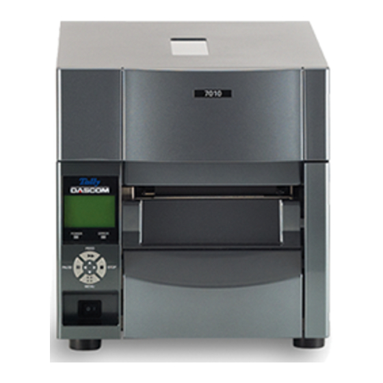
Tally Dascom 7010 Installation Manual
Peeler unit
Hide thumbs
Also See for 7010:
- Installation manual (9 pages) ,
- Installation manual (8 pages) ,
- Maintenance manual (255 pages)
Advertisement
Installation Guide
This guide is provided for use by service representatives who must install the
peeler unit. If the peeler is not installed, please contact your supplier.
Note
Installation requires a cross-point ('Phillips') screwdriver with magnetic tip and a
shaft at least 200 mm (8 inches) long.
(1)
Check to make sure that the printer's power switch is turned off then disconnect the
power cord.
(2)
Open the top cover and lift the thermal printhead and sensor arm.
Top cover
Thermal printhead
(3)
Remove the operation panel on
the front of the printer (2 screws).
When doing this, remove the
flexible cable that is connected
to the operation panel.
(4)
Remove the front right cover on
the front of the printer. (2 screws)
Caution
Head open lever
Flexible cable
Operation
panel
Front right
cover
7010 Peeler Unit
Sensor arm
Sensor arm open lever
Advertisement
Table of Contents

Subscribe to Our Youtube Channel
Related Manuals for Tally Dascom 7010


Summary of Contents for Tally Dascom 7010
-
Page 1: Installation Guide
Installation Guide 7010 Peeler Unit Caution This guide is provided for use by service representatives who must install the peeler unit. If the peeler is not installed, please contact your supplier. Note Installation requires a cross-point ('Phillips') screwdriver with magnetic tip and a shaft at least 200 mm (8 inches) long. - Page 2 Remove the front center cover. (2 screws) Front center cover Remove the plastic cover from the front center cover that you have removed. (2 screws) Note The plastic cover that you have removed is needed if the peeler unit is de-installed, so store it carefully.
- Page 3 Attach the connector of the peeler unit to the daughter board as shown in the figure. Note The connector cannot be connected if it is inserted in the wrong orientation unless force is used! Check the orientation of the connector carefully. Slide the release knob of the peeler unit to the left and open the peeler unit.
- Page 4 (11) Align the two tabs on the bottom of the 'front center cover' to the slits of the printer as it is slid in to the printer. The bottom plate of the front cover needs to be held up from below to ensure a good fit.
Need help?
Do you have a question about the 7010 and is the answer not in the manual?
Questions and answers