AudioCodes MP-124 User Manual
Sip cpe & access analog gateways
Hide thumbs
Also See for MP-124:
- User manual (486 pages) ,
- Hardware installation manual (44 pages) ,
- User manual (238 pages)
Table of Contents
Advertisement
Quick Links
Advertisement
Table of Contents

Related Manuals for AudioCodes MP-124


Summary of Contents for AudioCodes MP-124
- Page 1 User's Manual Version 5.2 Document #: LTRT-65409 September 2007 http://ArtTel.ru...
- Page 2 http://ArtTel.ru...
-
Page 3: Table Of Contents
Package Contents ....................37 3.2.3 Mounting the MP-124 ....................37 3.2.3.1 Mounting MP-124 on a Desktop.............. 38 3.2.3.2 Installing the MP-124 in a 19-inch Rack..........38 3.2.4 Cabling the MP-124 ....................40 3.2.4.1 Grounding the MP-124 ................40 3.2.4.2 Connecting MP-124 to the Ethernet Network ......... 40 3.2.4.3... - Page 4 MediaPack Series 4.3.4 Assigning an IP Address Using the CLI..............51 4.3.4.1 Accessing the CLI ................... 51 4.3.4.2 Assigning an IP Address ................. 52 Configuring Basic Parameters ................53 Web-based Management ..................55 Computer Requirements ..................55 Protection and Security Mechanisms..............55 5.2.1 User Accounts ......................56 5.2.2...
- Page 5 SIP User's Manual Contents 5.5.8.5 Caller ID Permissions................153 5.5.8.6 Call Waiting ................... 153 5.5.9 Configuring the Advanced Applications..............154 5.5.9.1 Configuring RADIUS Accounting Parameters........154 5.5.9.2 Configuring the FXO Parameters............156 5.5.9.3 Configuring the Voice Mail (VM) Parameters........160 Network Settings ....................
- Page 6 5.13.1.4 Assigning a Name to a Port ..............244 5.13.1.5 Viewing Ethernet Port Settings ............. 245 5.13.1.6 Viewing the Active Alarms Table............246 5.13.2 MP-124 ......................... 247 5.13.2.1 Accessing the Home Page..............247 5.13.2.2 Viewing Port Information ............... 248 5.13.2.3 Assigning a Name to a Port ..............248 5.13.2.4 Viewing Ethernet Port Information ............
- Page 7 SIP User's Manual Contents 7.2.2.6 Fax / Modem Transparent Mode............329 7.2.2.7 Fax / Modem Transparent with Events Mode ........329 7.2.3 Supporting V.34 Faxes ..................330 7.2.3.1 Using Bypass Mechanism for V.34 Fax Transmission......330 7.2.3.2 Using Relay mode for both T.30 and V.34 faxes ........330 7.2.4 Supporting V.152 Implementation ................
- Page 8 Getting Started with VLANS and Multiple IPs ............375 8.9.3.1 Integrating Using the Embedded Web Server ........376 8.9.3.2 Integrating Using the ini File..............378 Selected Technical Specifications..............381 MP-11x Specifications..................381 MP-124 Specifications ..................385 10 Supplied SIP Software Package..............389 SIP User's Manual Document #: LTRT-65409 http://ArtTel.ru...
- Page 9 Figure 3-9: MP-124 with Brackets for Rack Installation .................38 Figure 3-10: RJ-45 Connector Pinouts....................40 Figure 3-11: 50-pin Telco Connector (MP-124/FXS only)..............42 Figure 3-12: MP-124 in a 19-inch Rack with MDF Adaptor..............42 Figure 3-13: MP-124 RS-232 Connector Pinouts ..................43 Figure 4-1: Startup Process........................47 Figure 4-2: Quick Setup Screen ......................53...
- Page 10 MediaPack Series Figure 5-36: FXO Settings Screen ...................... 156 Figure 5-37: Voice Mail Screen ......................160 Figure 5-38: IP Settings Screen ......................164 Figure 5-39: Application Settings Screen .................... 168 Figure 5-40: NFS Settings Screen ...................... 170 Figure 5-41: IP Routing Tablre Screen....................173 Figure 5-42: VLAN Settings Screen ....................
- Page 11 SIP User's Manual Contents Figure 7-6: FXS / FXO Example......................353 Figure 7-7: Tel to IP Routing Screen....................355 Figure 7-8: Tel to IP Routing Screen....................356 Figure 8-1: Nat Functioning ......................... 366 Figure 8-2: VLAN Settings Screen - Example ..................376 Figure 8-3: IP Settings Screen - Example ...................
- Page 12 Table 2-1: MP-11x Front Panel LEDs Description .................24 Table 2-2: MP-11x Rear Panel Component Descriptions ..............25 Table 2-3: Reset Button Description on MP-124 Front Panel ..............26 Table 2-4: MP-124 Front Panel LEDs Description .................26 Table 2-5: MP-124 Rear Panel Component Descriptions ..............28 Table 2-6: MP-124 Rear Panel Ethernet LEDs Description ..............28...
- Page 13 Table 8-1: Traffic / Network Types and Priority ................... 374 Table 8-2: Example of VLAN and Multiple IPs Configuration.............. 375 Table 9-1: MP-11x Functional Specifications ..................381 Table 9-2: MP-124 Functional Specifications..................385 Table 10-1: Supplied Software Package ..................... 389 Version 5.2 September 2007 http://ArtTel.ru...
- Page 14 MediaPack Series Reader's Notes SIP User's Manual Document #: LTRT-65409 http://ArtTel.ru...
-
Page 15: Weee Eu Directive
SIP User's Manual Notices Notice This document describes the AudioCodes MediaPack series Voice over IP (VoIP) gateways. Information contained in this document is believed to be accurate and reliable at the time of printing. However, due to ongoing product improvements and revisions, AudioCodes cannot guarantee accuracy of printed material after the Date Published nor can it accept responsibility for errors or omissions. -
Page 16: Related Documentation
MediaPack series. • Throughout this manual, unless otherwise specified, the term MediaPack refers to the MP-124, MP-118, MP-114, and MP-112 VoIP gateways. • Throughout this manual, unless otherwise specified, the term MP-11x refers to the MP-118, MP-114, and MP-112 VoIP gateways. - Page 17 SIP User's Manual General Notes: • FXO (Foreign Exchange Office) is the interface replacing the analog telephone and connects to a Public Switched Telephone Network (PSTN) line from the Central Office (CO) or to a Private Branch Exchange (PBX). The FXO is designed to receive line voltage and ringing current, supplied from the CO or the PBX (just like an analog telephone).
- Page 18 MediaPack Series Reader's Notes SIP User's Manual Document #: LTRT-65409 http://ArtTel.ru...
-
Page 19: Overview
VoIP analog MediaPack gateways listed in the table below: Table 1-1: Supported Product Configurations Combined FXS / Number of Product Name Channels MP-124 MP-118 4 + 4 MP-114 2 + 2 MP-112* * The MP-112 differs from the MP-114 and MP-118 in that its configuration excludes the RS-232 connector, Lifeline option, and outdoor protection. -
Page 20: Mediapack Features
MediaPack Features This section provides a high-level overview of some of the many MediaPack supported features. For more updated information on the gateway’s supported features, refer to the latest MP-11x & MP-124 SIP Release Notes. 1.2.1 MP-11x Hardware Features The MP-11x series hardware features includes the following: Combined FXS/FXO gateways (4 FXS and 4 FXO ports on the MP-118;... -
Page 21: Hardware Features
LEDs on the front and rear panels provide information on the operating status of the gateway and the network interface. Reset button on the front panel restarts the MP-124 gateway, and is also used to restore the MP-124 parameters to their factory default settings. - Page 22 MediaPack Series Reader's Notes SIP User's Manual Document #: LTRT-65409 http://ArtTel.ru...
-
Page 23: Mediapack Physical Description
This section provides a physical description on the hardware (i.e., ports, buttons, and LEDs) on the front and rear panels of the MP-11x (refer to 'MP-11x Physical Description' on page 23) and MP-124 (refer to 'MP-124 Physical Description' on page 26) gateways. MP-11x Physical Description The subsections below provide a physical description of the front and rear panels of the MP-11x. -
Page 24: Table 2-1: Mp-11X Front Panel Leds Description
MediaPack Series The following table describes the MP-11x front panel LEDs: Table 2-1: MP-11x Front Panel LEDs Description Type Color State Definition Telephone The phone is ringing (incoming call, before Channels Blinking Interface answering). Status Fast Line malfunction Blinking Green Normal onhook position Offhook Ringing... -
Page 25: Mp-11X Rear Panel
SIP User's Manual 2. MediaPack Physical Description 2.1.2 MP-11x Rear Panel The figure below illustrates the rear panel of the MP-118, which is almost identical to the MP-114 and MP-112 models (differing only in the number of FXS / FXO ports). Figure 2-2: MP-11x (e.g., MP-118) Rear Panel Connectors The following table describes the MP-11x rear panel ports: Table 2-2: MP-11x Rear Panel Component Descriptions... -
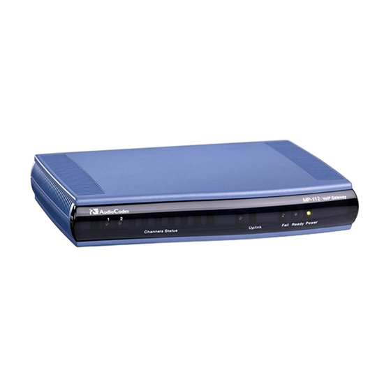
Page 26: Physical Description
MP-124 Front Panel The figure below illustrates the front layout of the MP-124. Figure 2-3: MP-124 Front Panel The table below describes the MP-124 Reset button located on the front panel. Table 2-3: Reset Button Description on MP-124 Front Panel Type... - Page 27 SIP User's Manual 2. MediaPack Physical Description Table 2-4: MP-124 Front Panel LEDs Description Label Type Color State Function Control Link Green Blinking Sending and receiving SIP messages Control Blank No traffic Packet Status Green Blinking Transmitting RTP (Real-Time Transport...
-
Page 28: Rear Panel
MediaPack Series 2.2.2 MP-124 Rear Panel The figure below illustrates the rear panel of the MP-124. Figure 2-4: MP-124 (FXS) Rear Panel Connectors The table below describes the MP-124 rear panel components. Table 2-5: MP-124 Rear Panel Component Descriptions Item #... -
Page 29: Installing The Mediapack
This section provides information on the installation procedure for the MP-11x (refer to 'Installing the MP-'11x on page 29) and the MP-124 (refer to 'Installing the MP-124' on page 36). For information on how to start using the gateway, refer to 'Getting Started' on page 45. -
Page 30: Package Contents
MediaPack Series 3.1.2 Package Contents Ensure that in addition to the MP-11x unit, the package contains the following items: AC power cable. Small plastic bag containing four anti-slide bumpers for desktop installation. A CD with software and documentation may be included. The MediaPack Fast Track Guide. -
Page 31: Mounting Mp-11X On A Desktop
SIP User's Manual 3. Installing the MediaPack 3.1.3.1 Mounting MP-11x on a Desktop Attach the four (supplied) anti-slide bumpers to the base of the MP-11x (refer to the figure item #1 in 'Mounting the MP-11x' on page 30) and place it on a desktop in the desired position. -
Page 32: Cabling The Mp-11X
MediaPack Series To install the MP-11x in a 19-inch rack, take these 3 steps: Attach one or two MP-11x devices to the shelf using the shelf-to-device screws (supplied). Position the shelf in the rack and line up its side holes with the rack frame holes. Attach the shelf to the rack using four standard rack screws (not supplied). -
Page 33: Connecting Mp-11X To The Network
SIP User's Manual 3. Installing the MediaPack To reduce the risk of fire, use only No. 26 AWG or larger Warning: telecommunication line cords. 3.1.4.1 Connecting MP-11x to the Network Follow the procedure below for connecting MP-11x directly to the Ethernet network. To connect MP-11x directly to the Ethernet network: Using a crossover Ethernet cable with RJ-45 connectors on either end, connect the MP-11x Ethernet port (labelled Ethernet), directly to the network. -
Page 34: Connecting Mp-11X To Fxs /Fxo Devices
MediaPack Series 3.1.4.2 Connecting MP-11x to FXS /FXO Devices Follow the procedure below for connecting MP-11x to FXO or FXS devices. To connect MP-11x to FXO or FXS devices: Using an RJ-11 two-wire telephone cords (refer to figure below for connector pinouts), connect the MP-11x to the required telephone interfaces: •... -
Page 35: Cabling The Mp-11X/Fxs Lifeline
SIP User's Manual 3. Installing the MediaPack Figure 3-6: PS/2 Connector Pinouts For information on establishing a serial communications link with the MP-11x, refer to Establishing a Serial Communications Link with the MediaPack. 3.1.4.4 Cabling the MP-11x/FXS Lifeline The Lifeline provides a wired analog POTS phone connection to any PSTN or PBX FXS port when there is no power, or when the network connection fails. -
Page 36: Connecting Mp-11X To Power
Cable the MP-124 (refer to 'Cabling the MP-124' on page 40). After connecting the MP-124 to the power source, the Ready and LAN LEDs on the front panel light up green (after a self-testing period of about 1 minute). Any malfunction changes the Ready LED to red. -
Page 37: Unpacking
Mounting the MP-124 The MP-124 offers the following mounting options: Desktop mounting ('Mounting the MP-124 on a Desktop' on page 38) Installed in a standard 19-inch rack ('Installing the MP-124 in a 19-inch Rack' on page Version 5.2 September 2007... -
Page 38: Mounting Mp-124 On A Desktop
3.2.3.2 Installing the MP-124 in a 19-inch Rack The MP-124 can be installed in a standard 19-inch rack by the addition of two short, equal- length brackets (supplied). The MP-124 with brackets for rack installation is shown in the figure below. - Page 39 Repeat steps 1 through 4 to attach the second bracket to the other side of the MP- 124. Position the MP-124 in the rack and line up the bracket holes with the rack frame holes. Use four standard rack screws (not supplied) to attach the MP-124 to the rack.
-
Page 40: Cabling The Mp-124
Connecting MP-124 to the Ethernet network (refer to 'Connecting MP-124 to the Ethernet Network' on page 40) Connecting MP-124 to FXS analog lines using a Telco cable (refer to 'Connecting MP- 124 to FXS Interface' on page 41) Connecting MP-124 RS-232 port to a PC (refer to 'Connecting MP-124 RS-232 Port to a PC' on page 43.) -
Page 41: Connecting Mp-124 To Fxs Interface
3. Installing the MediaPack 3.2.4.3 Connecting MP-124 to FXS Interface The MP-124 interfaces with the analog telephone interfaces by connecting to a main distribution frame (MDF) using a 50-pin Telco cable. To connect MP-124 to the FXS telephone interface: Wire the 50-pin Telco connectors according to the pinouts in the figures below. -
Page 42: Figure 3-11: 50-Pin Telco Connector (Mp-124/Fxs Only)
MediaPack Series Figure 3-11: 50-pin Telco Connector (MP-124/FXS only) Figure 3-12: MP-124 in a 19-inch Rack with MDF Adaptor SIP User's Manual Document #: LTRT-65409 http://ArtTel.ru... -
Page 43: Connecting Mp-124 Rs-232 Port To A Pc
3.2.4.4 Connecting MP-124 RS-232 Port to a PC Follow the procedure below to connect the MP-124 serial (RS-232) interface to a PC using a standard, straight-through cable with DB-9 connectors on either end. To connect MP-124 to a PC, take these 2 steps: Connect the DB-9 connector (refer to the figure below for connector pinouts), on one end of the cable, to the MP-124 RS-232 port (labeled RS-232). - Page 44 MediaPack Series Reader's Notes SIP User's Manual Document #: LTRT-65409 http://ArtTel.ru...
-
Page 45: Getting Started
SIP User's Manual 4. Getting Started Getting Started The gateway is supplied with default networking parameters (i.e., MAC and IP addresses, as listed in the table below) and with an application software (cmp file) residing on its flash memory (with factory default parameters). Before you begin configuring the gateway, refer to 'Configuration Concepts' on page a description of the available gateway configuration methods. -
Page 46: Startup Process
MediaPack Series Startup Process The startup process (illustrated in the following figure) begins when the gateway is reset (physically, using the Embedded Web Server, or using SNMP) and ends when the operational software is running. In the startup process, the network parameters, and software and configuration files are obtained. -
Page 47: Figure 4-1: Startup Process
SIP User's Manual 4. Getting Started Figure 4-1: Startup Process Version 5.2 September 2007 http://ArtTel.ru... -
Page 48: Assigning An Ip Address
MediaPack Series Assigning an IP Address To assign the gateway an IP address, use one of the following methods: HTTP using a Web browser (refer to 'Assigning an IP Address Using HTTP' on page 48). BootP (refer to 'Assigning an IP Address Using BootP' on page 49). Voice Menu using a standard touch-tone telephone connected to one of the FXS analog ports (refer to Assigning an IP Address Using the Voice Menu Guidance on page 50). -
Page 49: Assigning An Ip Address Using Bootp
SIP User's Manual 4. Getting Started Reconnect the gateway and your PC (if necessary) to the network. Restore your PC’s IP address and subnet mask to their original settings. If necessary, restart your PC and re-access the gateway via the Embedded Web Server with its newly assigned IP address. -
Page 50: Assigning An Ip Address Using The Voice Menu Guidance
MediaPack Series 4.3.3 Assigning an IP Address Using the Voice Menu Guidance Initial configuration of the gateway can be performed using a standard touch-tone telephone connected to one of the FXS analog ports. The voice menu can also be used to query and modify basic configuration parameters. -
Page 51: Assigning An Ip Address Using The Cli
SIP User's Manual 4. Getting Started The following configuration parameters can be queried or modified via the voice menu: Table 4-2: Configuration Parameters Available via the Voice Menu Item Number at Menu Description Prompt IP address Subnet mask Default Gateway IP address Primary DNS server IP address DHCP enable / disable MGCP call agent IP address (N/A) -
Page 52: Assigning An Ip Address
To access the CLI using the RS-232 port , take these 2 steps: Connect the gateway's RS-232 port to your PC (for MP-11x refer to Connecting the MP-11x RS-232 Port to Your PC on page 34; for MP-124, refer to Connecting the MP- 124 RS-232 Port to Your PC on page 43). -
Page 53: Configuring Basic Parameters
SIP User's Manual 4. Getting Started Configuring Basic Parameters To configure the gateway's basic parameters, use the Embedded Web Server’s ‘Quick Setup’ screen (shown in the figure below). For information on accessing the Embedded Web Server, refer to 'Accessing the Embedded Web Server' on page 58. Figure 4-2: Quick Setup Screen To configure basic SIP parameters, take these 10 steps: Access the ‘Quick Setup’... - Page 54 MediaPack Series When working with a Proxy server, set the ‘Working with Proxy’ field to ‘Yes’, and then enter the IP address of the primary Proxy server in the field ‘Proxy IP address’. When no Proxy is used, the internal routing table is used to route the calls. Enter the Proxy name in the field ‘Proxy Name’.
-
Page 55: Web-Based Management
SIP User's Manual 5. Web-based Management Web-based Management The gateway's Embedded Web Server is used for remote configuration of the gateway including loading of configuration files, as well as for online monitoring of the gateway. In addition, you can also remotely reset the gateway. The Embedded Web Server can be accessed from a standard Web browser such as Microsoft™... -
Page 56: User Accounts
MediaPack Series 5.2.1 User Accounts Up to five simultaneous users can be handled on gateway authentication via the Embedded Web Server. To prevent unauthorized access to the Embedded Web Server, two user accounts are available: primary and secondary. Each account is composed of three attributes: username, password, and access level. -
Page 57: Limiting The Embedded Web Server To Read-Only Mode
SIP User's Manual 5. Web-based Management The first time a Web browser request is made, users are requested to provide their account's username and password to obtain access. If the Embedded Web Server is left idle for more than five minutes, the session expires and the user is required to re-enter username and password. -
Page 58: Accessing The Embedded Web Server
MediaPack Series Accessing the Embedded Web Server You can access the gateway's Embedded Web Server by following the procedure below. To access the Embedded Web Server, take these 4 steps: Open a standard Web-browsing application (for a list of supported Web browsers, refer to 'Computer Requirements' on page 55). -
Page 59: Getting Acquainted With The Web Interface
SIP User's Manual 5. Web-based Management Getting Acquainted with the Web Interface The figure below displays the general layout of the interface of the Embedded Web Server. The Embedded Web Server features the following components: Title bar: contains three configurable elements: corporate logo, a background image, and the product's name. -
Page 60: Main Menu Bar
MediaPack Series 5.4.1 Main Menu Bar The main menu bar of the Embedded Web Server provides the following menus: Quick Setup: Accesses the 'Quick Setup' screen for quickly configuring the gateway's basic settings.For a full list of configurable parameters, directly access the Protocol Management and Advanced Configuration menus. -
Page 61: Searching For Configuration Parameters
SIP User's Manual 5. Web-based Management 5.4.4 Searching for Configuration Parameters The Embedded Web Server provides a search engine that allows you to search any ini file parameter that is configurable by the Web server. The Search button, located near the bottom of the Main menu bar is used to perform parameter searches. -
Page 62: Figure 5-3: Searched Parameter Highlighted In Screen
MediaPack Series In the searched result list, click the required parameter to open the screen in which the parameter appears; the searched parameter is highlighted in green in the screen for easy identification, as shown in the figure below. Figure 5-3: Searched Parameter Highlighted in Screen If the searched parameter is not located, the "No Matches Found For This Note: String"... -
Page 63: Customizing The Web Interface
SIP User's Manual 5. Web-based Management 5.4.5 Customizing the Web Interface You can customize the gateway's Embedded Web Server interface to suit your specific corporate logo and product naming conventions. The following Web interface elements can be customized: Main corporate logo displayed on the title bar (refer to 'Replacing the Main Corporate Logo' on page 63) Background image displayed on the title bar (refer to 'Replacing the Background Image File' on page 66) -
Page 64: Figure 5-6: Image Download Screen
MediaPack Series 5.4.5.1.1 Replacing the Main Corporate Logo with an Image File You can replace the logo in the Web interface's title bar using either the Embedded Web Server or the ini file. To replace the default logo with your own corporate image via the Embedded Web Server, take these 7 steps: Access the gateway's Embedded Web Server (refer to 'Accessing the Embedded Web Server' on page 58). -
Page 65: Table 5-3: Customizable Logo Ini File Parameters
SIP User's Manual 5. Web-based Management Use a gif, jpg or jpeg file for the logo image. It is important that the image file Note: has a fixed height of 59 pixels (the width can be configured up to a maximum of 339 pixels). -
Page 66: Replacing The Background Image File
MediaPack Series 5.4.5.2 Replacing the Background Image File The background image file is duplicated across the width of the screen. The number of times the image is duplicated depends on the width of the background image and screen resolution. When choosing your background image, keep this in mind. The background image file can be replaced using either the Embedded Web Server or the ini file. -
Page 67: Customizing The Product Name
SIP User's Manual 5. Web-based Management To replace the background image via the ini file, take these 3 steps: Place your background image file in the same folder as where the device’s ini file is located (i.e., the same location defined in the BootP/TFTP configuration utility). For detailed information on the BootP/TFTP, refer to the SIP Series Reference Manual). -
Page 68: Creating A Login Welcome Message
MediaPack Series 5.4.5.4 Creating a Login Welcome Message You can create a Welcome message box (alert message) that appears (see figure below for an example) after each successful login to the gateway's Embedded Web Server. The ini file parameter table WelcomeMessage allows you to create the Welcome message. Up to 20 lines of character strings can be defined for the message. -
Page 69: Protocol Management
SIP User's Manual 5. Web-based Management Protocol Management The Protocol Management menu is used to configure the gateway's SIP parameters and tables. Throughout this section, parameters enclosed in square brackets ([...]) depict Note: the ini file parameters that correspond to the Embedded Web Server parameters. -
Page 70: General Parameters
MediaPack Series 5.5.1.1 General Parameters The General Parameters option is used to configure general SIP parameters. To configure the general SIP protocol parameters, take these 4 steps: Open the 'General Parameters' screen (Protocol Management menu > Protocol Definition submenu > General Parameters option). Figure 5-8: General Screen SIP User's Manual Document #: LTRT-65409... -
Page 71: Table 5-8: General Parameters (Protocol Definition)
SIP User's Manual 5. Web-based Management Configure the parameters according to the table below. Click the Submit button to save your changes. To save the changes to flash memory, refer to 'Saving Configuration' on page 238. Table 5-8: General Parameters (Protocol Definition) Parameter Description PRACK Mode... - Page 72 MediaPack Series Table 5-8: General Parameters (Protocol Definition) Parameter Description Enable Early Media If enabled, the gateway sends 183 Session Progress response with SDP (instead of 180 Ringing), allowing the media stream to be set up prior to [EnableEarlyMedia] the answering of the call. [0] Disable = Early Media is disabled (default).
- Page 73 SIP User's Manual 5. Web-based Management Table 5-8: General Parameters (Protocol Definition) Parameter Description Fax Signaling Method Determines the SIP signaling method used to establish and convey a fax session after a fax is detected. [IsFaxUsed] [0] No Fax = No fax negotiation using SIP signaling. Fax transport method is according to the parameter FaxTransportMode (default).
- Page 74 MediaPack Series Table 5-8: General Parameters (Protocol Definition) Parameter Description SIP TCP Local Port Local TCP port used to receive SIP messages. The default value is 5060. [TCPLocalSIPPort] SIP TLS Local Port Local TLS port used to receive SIP messages. The default value is 5061.
- Page 75 SIP User's Manual 5. Web-based Management Table 5-8: General Parameters (Protocol Definition) Parameter Description Enable Remote Party ID Enable Remote-Party-ID (RPI) headers for calling and called numbers for Tel IP calls. [EnableRPIheader] Valid options include: [0] Disable (default). [1] Enable = RPI headers are generated in SIP INVITE messages for both called and calling numbers.
- Page 76 MediaPack Series Table 5-8: General Parameters (Protocol Definition) Parameter Description Enable History-Info Enables usage of the History-Info header. Header Valid options include: [EnableHistoryInfo] [0] Disable = Disable (default) [1] Enable = Enable UAC Behavior: Initial request: The History-Info header is equal to the Request URI. If a PSTN Redirect number is received, it is added as an additional History- Info header with an appropriate reason.
- Page 77 SIP User's Manual 5. Web-based Management Table 5-8: General Parameters (Protocol Definition) Parameter Description Use Source Number as Applicable to Tel-to-IP calls. Display Name [0] No = The Tel Source Number is used as the IP Source Number and [UseSourceNumberAsD the Tel Display Name is used as the IP Display Name (if Tel Display isplayName] Name is received).
- Page 78 MediaPack Series Table 5-8: General Parameters (Protocol Definition) Parameter Description Determines the method used to play Ringback tone to the Tel side. [0] Play Ringback Tone to Don't Play = Ringback Tone isn't played. [PlayRBTone2Tel] [1] Play Local = Ringback Tone is played to the Tel side of the call when 180/183 response is received.
- Page 79 SIP User's Manual 5. Web-based Management Table 5-8: General Parameters (Protocol Definition) Parameter Description Enable GRUU Determines whether or not the Globally Routable User Agent URIs (GRUU) mechanism is used. [EnableGRUU] Valid options include: [0] Disable = Disable (default) [1] Enable = Enable The gateway obtains a GRUU by generating a normal REGISTER request.
- Page 80 MediaPack Series Table 5-8: General Parameters (Protocol Definition) Parameter Description Subject Defines the value of the Subject header in outgoing INVITE messages. If not specified, the Subject header isn't included (default). [SIPSubject] The maximum length of the subject is limited to 50 characters. Multiple Packetization Determines whether the 'mptime' attribute is included in the outgoing SDP.
- Page 81 SIP User's Manual 5. Web-based Management Table 5-8: General Parameters (Protocol Definition) Parameter Description Retransmission Parameters SIP T1 Retransmission The time interval (in msec) between the first transmission of a SIP Timer [msec] message and the first retransmission of the same message. The default is 500.
-
Page 82: Proxy & Registration Parameters
MediaPack Series 5.5.1.2 Proxy & Registration Parameters The Proxy & Registration option is used to configure parameters that are associated with Proxy and Registration. To configure the Proxy & Registration parameters, take these 4 steps: Open the 'Proxy & Registration' parameters screen (Protocol Management menu > Protocol Definition submenu >... -
Page 83: Table 5-9: Proxy & Registration Parameters
SIP User's Manual 5. Web-based Management Configure the Proxy and Registration parameters according to the following table. Click the Submit button to save your changes, or click the Register or Un-Register buttons to save your changes and register / unregister to a Proxy / Registrar. To save the changes to flash memory, refer to 'Saving Configuration' on page 238. - Page 84 MediaPack Series Table 5-9: Proxy & Registration Parameters Parameter Description First Redundant Proxy IP addresses of the first redundant Proxy you are using. IP Address Enter the IP address as FQDN or in dotted decimal notation (e.g., 192.10.1.255). You can also specify the selected port in the format <IP [ProxyIP] Address>:<port>.
- Page 85 SIP User's Manual 5. Web-based Management Table 5-9: Proxy & Registration Parameters Parameter Description Proxy Load Balancing Enables the usage of the Proxy Load Balancing mechanism. Method [0] Disable = Load Balancing is disabled (default). [ProxyLoadBalancing [1] Round Robin = Round Robin. Method] [2] Random Weights = Random Weights.
- Page 86 MediaPack Series Table 5-9: Proxy & Registration Parameters Parameter Description Enable Proxy Keep Determines whether Keep-Alive with the Proxy is enabled or disabled. Alive [0] Disable = Disable (default)\ [EnableProxyKeepAli [1] Using OPTIONS = Enable Keep alive with Proxy using OPTIONS [2] Using REGISTER = Enable Keep alive with Proxy using REGISTER If EnableProxyKeepAlive = 1, SIP OPTIONS message is sent every ProxyKeepAliveTime.
- Page 87 SIP User's Manual 5. Web-based Management Table 5-9: Proxy & Registration Parameters Parameter Description Use Routing Table for Use the internal Tel to IP routing table to obtain the URI Host name and Host Names and (optionally) an IP profile (per call), even if Proxy server is used. Profiles [0] Disable = Don't use (default).
- Page 88 MediaPack Series Table 5-9: Proxy & Registration Parameters Parameter Description Registrar IP Address IP address (numerical or FQDN) and optionally port number of Registrar server. [RegistrarIP] Enter the IP address in dotted format notation, for example, 201.10.8.1:<5080>. Notes: If not specified, the REGISTER request is sent to the primary Proxy server (refer to 'Proxy IP address' parameter).
- Page 89 SIP User's Manual 5. Web-based Management Table 5-9: Proxy & Registration Parameters Parameter Description Miscellaneous parameters Gateway Name Assigns a name to the gateway (e.g., 'gateway1.com'). Ensure that the name you choose is the one that the Proxy is configured with to identify your [SIPGatewayName] gateway.
- Page 90 MediaPack Series Table 5-9: Proxy & Registration Parameters Parameter Description Proxy DNS Query Type Enables the use of DNS Naming Authority Pointer (NAPTR) and Service Record (SRV) queries to discover Proxy servers. [ProxyDNSQueryType Valid options include: [0] A-Record = A-Record (default) [1] SRV = SRV [2] NAPTR = NAPTR If set to A-Record [0], no NAPTR or SRV queries are performed.
- Page 91 SIP User's Manual 5. Web-based Management Table 5-9: Proxy & Registration Parameters Parameter Description Number of RTX Before Number of retransmitted INVITE/REGISTER messages before call is routed Hot-Swap (hot swap) to another Proxy/Registrar. The valid range is 1 to 30. The default value is 3. [HotSwapRtx] Note: This parameter is also used for alternative routing using the Tel to IP Routing table.
-
Page 92: Coders
MediaPack Series Table 5-9: Proxy & Registration Parameters Parameter Description Challenge Caching Determines the mode used for Challenge Caching. Challenge Caching is Mode used to reduce the number of SIP messages transmitted through the network. The first request to the Proxy is sent without authorization. The [SIPChallengeCachin Proxy sends a 401/407 response with a challenge. -
Page 93: Figure 5-10: Coders Screen
SIP User's Manual 5. Web-based Management To configure the gateway's coders, take these 9 steps: Open the 'Coders' screen (Protocol Management menu > Protocol Definition submenu > Coders option). Figure 5-10: Coders Screen From the 'Coder Name' drop-down list, select the coder you want to use. For the full list of available coders and their corresponding attributes, refer to the table below. -
Page 94: Table 5-10: Supported Coders
MediaPack Series Notes: • Each coder (i.e., 'Coder Name') can appear only once. • If packetization time and / or rate are not specified, the default value is applied. • The ptime specifies the packetization time the gateway expects to receive. -
Page 95: Dtmf & Dialing Parameters
SIP User's Manual 5. Web-based Management Table 5-10: Supported Coders Coder Name Packetization Time Rate Payload Type Silence Suppression 10, 20 (default), 30, Always 64 Dynamic (0-120) N/A G.711U-law_VBD 40, 50, 60, 80, 100, [g711UlawVbd] T.38 [t38fax] 5.5.1.4 DTMF & Dialing Parameters The DTMF &... -
Page 96: Table 5-11: Dtmf And Dialing Parameters
MediaPack Series Configure the DTMF and dialing parameters according to the table below. Click the Submit button to save your changes. To save the changes to flash memory, refer to 'Saving Configuration' on page 238. Table 5-11: DTMF and Dialing Parameters Parameter Description Max Digits in Phone Num... - Page 97 SIP User's Manual 5. Web-based Management Table 5-11: DTMF and Dialing Parameters Parameter Description to 5 Tx DTMF Option Determines a single or several preferred transmit DTMF negotiation methods. [TxDTMFOption] Valid options include: [0] Not Supported = No negotiation, DTMF digits are sent according to the parameters DTMFTransportType and RFC2833PayloadType (default).
- Page 98 MediaPack Series Table 5-11: DTMF and Dialing Parameters Parameter Description Hook-Flash Option Supported hook-flash Transport Type (method by which hook-flash is sent and received). [HookFlashOption] Valid options include: [0] Not Supported = Hook-Flash indication isn't sent (default) [1] INFO = Send proprietary INFO message with Hook-Flash indication [4] RFC 2833 Notes: FXO gateways support the receiving of RFC 2833 Hook-Flash signals.
-
Page 99: Configuring The Advanced Parameters
SIP User's Manual 5. Web-based Management Table 5-11: DTMF and Dialing Parameters Parameter Description [0] Disable = '*' or '#' terminate number collection (default). Enable Special Digits [IsSpecialDigits] [1] Enable = if you want to allow '*' and '#' to be used for telephone numbers dialed by a user or entered for the endpoint telephone number. -
Page 100: General Parameters
MediaPack Series 5.5.2.1 General Parameters The General Parameters option is used to configure general control protocol parameters. To configure the advanced general protocol parameters, take these 4 steps: Open the 'General Parameters' screen (Protocol Management menu > Advanced Parameters submenu > General Parameters option). Figure 5-12: General Parameters Screen (Advanced Parameters Submenu) SIP User's Manual Document #: LTRT-65409... -
Page 101: Table 5-12: General Parameters (Advanced Parameters)
SIP User's Manual 5. Web-based Management Configure the parameters according to the table below. Click the Submit button to save your changes. To save the changes to flash memory, refer to 'Saving Configuration' on page 238. Table 5-12: General Parameters (Advanced Parameters) Parameter Description [0] Disable = gateway accepts all SIP calls (default). - Page 102 MediaPack Series Table 5-12: General Parameters (Advanced Parameters) Parameter Description [0] Disable = Disabled (default). Enable Digit Delivery to Tel [EnableDigitDelivery] [1] Enable = Enable Digit Delivery feature for the FXO/FXS gateway The digit delivery feature enables sending DTMF digits to the gateway's port after the call is answered [line offhooked (FXS) or seized (FXO)].
- Page 103 SIP User's Manual 5. Web-based Management Table 5-12: General Parameters (Advanced Parameters) Parameter Description Reanswer Time The time period after user hangs up the phone and before the call is disconnected (FXS). Also called regret time. [RegretTime] The valid range is 0 to 255 (in seconds). The default value is 0. Disconnect and Answer Supervision [0] Disable = Disable the polarity reversal service (default).
- Page 104 MediaPack Series Table 5-12: General Parameters (Advanced Parameters) Parameter Description Broken Connection The amount of time (in 100 msec units) an RTP packet isn't received, Timeout after which a call is disconnected. The valid range is 1 to 1000. The default value is 100 (i.e., 10 seconds). [BrokenConnectionEvent Timeout] Notes:...
- Page 105 SIP User's Manual 5. Web-based Management Table 5-12: General Parameters (Advanced Parameters) Parameter Description CDR and Debug CDR Server IP Address Defines the destination IP address for CDR logs. The default value is a null string that causes the CDR messages to be [CDRSyslogServerIP] sent with all Syslog messages.
- Page 106 MediaPack Series Table 5-12: General Parameters (Advanced Parameters) Parameter Description Misc. Parameters Progress Indicator to IP For Analog (FXS/FXO) gateways: [ProgressIndicator2IP] [0] No PI = For Tel-to-IP calls, the gateway sends '180 Ringing' SIP response to IP after placing a call to phone (FXS) or to PBX (FXO). [1] PI = 1, [8] PI = 8: For Tel-to-IP calls, if EnableEarlyMedia = 1, the gateway sends 183 session in progress message + SDP, immediately after a call is placed to Phone/PBX.
- Page 107 SIP User's Manual 5. Web-based Management Table 5-12: General Parameters (Advanced Parameters) Parameter Description Delay After Reset [sec] Defines the amount of time (in seconds) the gateway's operation is delayed after a reset cycle. [GWAppDelayTime] The valid range is 0 to 45. The default value is 7 seconds. Note: This feature helps to overcome connection problems caused by some LAN routers or IP configuration parameters change by a DHCP Server.
-
Page 108: Supplementary Services
MediaPack Series Table 5-12: General Parameters (Advanced Parameters) Parameter Description Out-Of-Service Behavior Determines the behavior of FXS endpoints that are not defined (in the Endpoint Phone Number table), and the behavior of all FXS endpoints [FXSOOSBehavior] when a Busy-Out condition exists. [0] None = Normal operation. -
Page 109: Figure 5-13: Supplementary Services Screen
SIP User's Manual 5. Web-based Management To configure the supplementary services' parameters, take these 4 steps: Open the 'Supplementary Services' screen (Protocol Management menu > Advanced Parameters submenu > Supplementary Services option). Figure 5-13: Supplementary Services Screen Configure the supplementary services parameters according to the table below. Click the Submit button to save your changes, or click the Subscribe to MWI or Unsubscribe to MWI buttons to save your changes and to subscribe / unsubscribe to the MWI server. -
Page 110: Table 5-13: Supplementary Services Parameters
MediaPack Series Table 5-13: Supplementary Services Parameters Parameter Description [0] Disable = Disables the Hold service. Enable Hold [EnableHold] [1] Enable = Enables the Hold service (default). If the Hold service is enabled, a user can activate Hold (or Unhold) using the hook-flash. - Page 111 SIP User's Manual 5. Web-based Management Table 5-13: Supplementary Services Parameters Parameter Description [0] Disable = Disable the Call Waiting service. Enable Call Waiting [EnableCallWaiting] [1] Enable = Enable the Call Waiting service (default). If enabled, when an FXS gateway receives a call on a busy endpoint, it responds with a 182 response (and not with a 486 busy).
- Page 112 MediaPack Series Table 5-13: Supplementary Services Parameters Parameter Description Caller ID Type Defines one of the following standards for detection (FXO) and generation (FXS) of Caller ID, and detection (FXO) generation (FXS) of MWI (when [CallerIDType] specified) signals: [0] Bellcore = Caller ID and MWI (default) [1] ETSI = Caller ID and MWI [2] NTT [4] Britain...
- Page 113 SIP User's Manual 5. Web-based Management Table 5-13: Supplementary Services Parameters Parameter Description [0] Disable = MWI information isn't sent to display (default). MWI Display [MWIDisplay] [1] Enable = MWI information is sent to display. If enabled, the gateway generates an MWI FSK message that is displayed on the MWI display.
-
Page 114: Metering Tones
MediaPack Series Table 5-13: Supplementary Services Parameters Parameter Description Conference ID Defines the Conference Identification string (up to 16 characters). The default value is 'conf'. [ConferenceID] The gateway uses this identifier in the Conference-initiating INVITE that is sent to the media server when Enable3WayConference is set to 1. For example: ConferenceID = MyConference. -
Page 115: Figure 5-15: Charge Codes Table Screen
SIP User's Manual 5. Web-based Management Table 5-14: Metering Tones Parameters Parameter Description Generate Metering Tones Determines the method used to configure the metering tones that are generated to the Tel side (FXS gateways only). [PayPhoneMeteringMode] [0] Disable = Metering tones aren't generated (default). [1] Internal Table = Metering tones are generated according to the internal table configured by the parameter ChargeCode. -
Page 116: Keypad Features
MediaPack Series Use the table to define up to 25 different charge codes (each charge code is defined in a single row). Each code can include from a single and up to four different time periods in a day (24 hours). Each time period is composed of: •... -
Page 117: Figure 5-16: Keypad Features Screen
SIP User's Manual 5. Web-based Management To configure the keypad features, take these 4 steps: Open the 'Keypad Features' screen (Protocol Management menu > Advanced Parameters submenu > Keypad Features option). Figure 5-16: Keypad Features Screen Configure the Keypad Features according to the table below. Click the Submit button to save your changes. -
Page 118: Table 5-15: Keypad Features Parameters
MediaPack Series Table 5-15: Keypad Features Parameters Parameter Description Forward Note that the forward type and number can be viewed in the Call Forward Table (refer to 'Call Forward' on page 151) Unconditional Keypad sequence that activates the immediate forward option. [KeyCFUnCond] No Answer Keypad sequence that activates the forward on no answer option. -
Page 119: Stand-Alone Survivability
SIP User's Manual 5. Web-based Management Table 5-15: Keypad Features Parameters Parameter Description Deactivate Keypad sequence that deactivates the delayed hotline option. After the sequence is pressed a confirmation tone is heard. [KeyHotLineDeact] Note: Applicable only to FXS endpoints. Transfer Blind Keypad sequence that activates the blind transfer option. -
Page 120: Figure 5-17: Stand-Alone Survivability Screen
MediaPack Series established, the SAS switches to pre-Normal mode. In this mode, the SAS maintains all terminations of existing calls while any new SIP call signaling (issued by new INVITE session) is transacted to/from the IP Centrex server. This requires the SAS to maintain a database of current active calls so that after releasing all calls established during Emergency mode, the SAS can continue functioning in Normal mode. -
Page 121: Configuring The Number Manipulation Tables
SIP User's Manual 5. Web-based Management 5.5.3 Configuring the Number Manipulation Tables The VoIP gateway provides four Number Manipulation tables for incoming and outgoing calls. These tables are used to modify the destination and source telephone numbers so that the calls can be routed correctly. The Manipulation Tables include: Destination Phone Number Manipulation Table for IP-to-Tel calls Destination Phone Number Manipulation Table for Tel-to-IP calls... -
Page 122: Figure 5-18: Source Phone Number Manipulation Table For Tel-To-Ip Calls
MediaPack Series To configure the Number Manipulation tables, take these 5 steps: Open the required 'Number Manipulation' screen (Protocol Management menu > Manipulation Tables submenu); the relevant Manipulation table screen is displayed (e.g., 'Source Phone Number Manipulation Table for Tel IP Calls' screen). Figure 5-18: Source Phone Number Manipulation Table for Tel-to-IP Calls The figure above exemplifies the use of the manipulation rules in the 'Source Phone Number Manipulation Table for Tel IP Calls':... -
Page 123: Table 5-17: Number Manipulation Parameters
SIP User's Manual 5. Web-based Management Table 5-17: Number Manipulation Parameters Parameter Description Destination (called) telephone number prefix. An asterisk (*) represents Destination Prefix any number. Source (caller) telephone number prefix. An asterisk (*) represents any Source Prefix number. Source IP address of the call (obtained from the Contact header in the Source IP (Applicable only to the INVITE message). -
Page 124: Dialing Plan Notation
MediaPack Series 5.5.3.1 Dialing Plan Notation The dialing plan notation applies to all the Manipulation tables as well as to the Tel to IP Routing table (refer to 'Tel to IP Routing Table' on page 129) and to IP to Hunt Group Routing table (refer to 'IP to Hunt Group Routing' on page 132). -
Page 125: Figure 5-19: Phone Context Table Screen
SIP User's Manual 5. Web-based Management To configure the Phone-Context tables, take these 6 steps: Open the 'Phone Context Table' screen (Protocol Management menu > Manipulation Tables submenu > Phone Context Table option). Figure 5-19: Phone Context Table Screen From the 'Add Phone Context As Prefix' drop-down list, select 'Enable' to add the received Phone-Context parameter as a prefix to outgoing Called and Calling numbers, if necessary. -
Page 126: Configuring The Routing Tables
MediaPack Series Table 5-19: Phone-Context Parameters Parameter Description Add Phone Context As Prefix Determines whether or not the received Phone-Context parameter is added as a prefix to the outgoing Called and Calling numbers. [AddPhoneContextAsPrefix] Valid options include: [0] Disable = Disable (default). [1] Enable = Enable. -
Page 127: General Parameters
SIP User's Manual 5. Web-based Management 5.5.4.1 General Parameters The General Parameters option is used to configure the gateway's IP-to-Tel and Tel-to-IP routing parameters. To configure the general routing parameters, take these 4 steps: Open the 'General Parameters' screen (Protocol Management menu > Routing Tables submenu >... - Page 128 If enabled, Add port number (single digit in the range 1 to 8 for 8-port gateways, 2 digits in the range 01 to 24 for MP-124) as a prefix to the called (destination) phone number for Tel IP incoming calls.
-
Page 129: Tel To Ip Routing Table
SIP User's Manual 5. Web-based Management Table 5-20: General Parameters (Routing Tables) Parameter Description Max Allowed Packet Packet loss percentage at which the IP connection is considered a failure. Loss for Alt Routing [%] The range is 1 to 20%. The default value is 20%. [IPConnQoSMaxAllowe dPL] Max Allowed Delay for... -
Page 130: Figure 5-21: Tel To Ip Routing Screen
MediaPack Series Alternative Routing (when Proxy isn't used): an alternative IP destination for telephone number prefixes is available. To associate an alternative IP address to called telephone number prefix, assign it with an additional entry (with a different IP address), or use an FQDN that resolves to two IP addresses. The call is sent to the alternative destination when one of the following occurs: •... -
Page 131: Table 5-21: Tel To Ip Routing Table
SIP User's Manual 5. Web-based Management From the 'Tel to IP Routing Mode' drop-down list, select the required Tel to IP routing mode (refer to the table below). From the 'Routing Index' drop-down list, select the range of entries that you want to add. -
Page 132: Ip To Hunt Group Routing
MediaPack Series Table 5-21: Tel to IP Routing Table Parameter Description A read-only field representing the Quality of Service of the destination IP Status address: n/a = Alternative Routing feature is disabled. OK = IP route is available Ping Error = No ping to IP destination; route is not available QoS Low = Bad QoS of IP destination;... -
Page 133: Figure 5-22: Ip To Hunt Group Routing Table Screen
SIP User's Manual 5. Web-based Management You can configure the 'Hunt Group Settings' table to determine the method in which new calls are assigned to channels within the Hunt Groups (a different method for each Hunt Group can be configured). For information on how to enable this option, refer to 'Configuring the Hunt Group Settings' on page 145. -
Page 134: Internal Dns Table
MediaPack Series Table 5-22: IP to Hunt Group Routing Table Parameter Description IP to Tel Routing Mode Defines order between routing calls to Hunt group and manipulation of destination number. [RouteModeIP2Tel] [0] Route calls before manipulation = IP-to-Tel calls are routed before the number manipulation rules are applied (default). -
Page 135: Internal Srv Table
SIP User's Manual 5. Web-based Management To configure the internal DNS table, take these 7 steps: Open the 'Internal DNS Table' screen (Protocol Management menu > Routing Tables submenu > Internal DNS Table option). Figure 5-23: Internal DNS Table Screen In the 'Domain Name' field, enter the host name to be translated. -
Page 136: Reasons For Alternative Routing
MediaPack Series If the Internal SRV table is configured, the gateway first tries to resolve a Note: domain name using this table. If the domain name isn't found, the gateway performs an SRV resolution using an external DNS server. To configure the Internal SRV table, take these 9 steps: Open the 'Internal SRV Table' screen (Protocol Management menu >... -
Page 137: Figure 5-25: Reasons For Alternative Routing Screen
SIP User's Manual 5. Web-based Management You can use the 'Reasons for Alternative Routing' screen in the following example scenarios: For Tel-to-IP calls: when there is no response to an INVITE message (after INVITE retransmissions), and the gateway then issues an internal 408 'No Response' implicit release reason. -
Page 138: Configuring The Profile Definitions
MediaPack Series 5.5.5 Configuring the Profile Definitions The Profiles feature provides the gateway with high-level adaptation when connected to a variety of equipment (from both Tel and IP sides) and protocols, each of which requires different system behavior. You can assign different Profiles (behavior) on a per call basis, using the Tel to IP and IP to Trunk Group Routing tables, or associate different Profiles to the gateway's endpoints. -
Page 139: Figure 5-26: Coder Group Settings Screen
SIP User's Manual 5. Web-based Management To configure coder groups, take these 11 steps: Open the 'Coder Group Settings' screen (Protocol Management menu > Profile Definitions submenu > Coder Group Settings option). Figure 5-26: Coder Group Settings Screen From the 'Coder Group ID' drop-down list, select a coder group ID that you want to add (up to four coder groups can be configured). -
Page 140: Tel Profile Settings
MediaPack Series Notes: • Each coder can appear only once. • The ptime specifies the packetization time the gateway expects to receive. The gateway always uses the ptime requested by the remote side for sending RTP packets. If not specified, the packetization time (ptime) gets a default value. - Page 141 SIP User's Manual 5. Web-based Management To configure Tel Profiles, take these 9 steps: Open the 'Tel Profile Settings' screen (Protocol Management menu > Profile Definitions submenu > Tel Profile Settings option). From the 'Profile ID' drop-down list, select the Tel Profile identification number you want to edit (up to four Tel Profiles can be configured).
-
Page 142: Ip Profile Settings
MediaPack Series From the 'Profile Preference' drop-down list, select the preference (1-20) of the current Profile. The preference option is used to determine the priority of the Profile. Where '20' is the highest preference value. If both IP and Tel profiles apply to the same call, the coders and other common parameters (noted by an asterisk in the description of the parameter TelProfile) of the preferred Profile are applied to that call. -
Page 143: Figure 5-27: Ip Profile Settings Screen
SIP User's Manual 5. Web-based Management To configure the IP Profile settings, take these 9 steps: Open the 'IP Profile Settings' screen (Protocol Management menu > Profile Definitions submenu > IP Profile Settings option. Figure 5-27: IP Profile Settings Screen From the 'Profile ID' drop-down list, select the IP Profile you want to edit (up to four IP Profiles can be configured). -
Page 144: Configuring The Endpoint Phone Numbers
MediaPack Series From the 'Profile Preference' drop-down list, select the preference (1-20) of the current Profile. The preference option is used to determine the priority of the Profile. Where '20' is the highest preference value. If both IP and Tel profiles apply to the same call, the coders and other common parameters (noted by an asterisk in the description of the parameter IPProfile) of the preferred Profile are applied to that call. -
Page 145: Configuring The Hunt Group Settings
SIP User's Manual 5. Web-based Management Table 5-23: Endpoint Phone Number Table Parameter Description The numbers (1-8) in the Channel(s) fields represent the ports on the back Channel(s) of the VoIP gateway. To enable a VoIP gateway channel, you must enter the port (channel) number. -
Page 146: Figure 5-29: Hunt Group Settings Screen
MediaPack Series To configure the Hunt Group Settings table, take these 5 steps: Open the 'Hunt Group Settings' screen (Protocol Management menu > Hunt Group Settings). Figure 5-29: Hunt Group Settings Screen From the 'Routing Index' drop-down list, select the range of entries that you want to edit (up to 24 entries can be configured). -
Page 147: Table 5-24: Hunt Group Settings Parameters
SIP User's Manual 5. Web-based Management Table 5-24: Hunt Group Settings Parameters Mode Description Hunt Group ID to which you want to determine the method in which new calls Hunt Group ID are assigned to channels within the Hunt group. Method in which new calls are assigned to channels within the Hunt Group Channel Select entered in the 'Hunt Group ID' field:... -
Page 148: Configuring The Endpoint Settings
MediaPack Series 5.5.8 Configuring the Endpoint Settings The Endpoint Settings submenu enables you to configure port-specific parameters. 5.5.8.1 Authentication The 'Authentication' screen (typically used for FXS gateways) defines a username and password combination for authenticating each gateway port. The 'Authentication Mode' parameter (described in 'Proxy & Registration Parameters' on page 82) determines whether authentication is performed per port or for the entire gateway. -
Page 149: Automatic Dialing
SIP User's Manual 5. Web-based Management 5.5.8.2 Automatic Dialing The 'Automatic Dialing' screen is used to define telephone numbers that are automatically dialed when a specific port is used. You can also configure automatic dialing using the ini file parameter TargetOfChannel (refer to 'Analog Telephony Parameters' on page 294). -
Page 150: Caller Id
MediaPack Series Notes: • After a ring signal is detected on an 'Enabled' FXO port, the gateway initiates a call to the destination number without seizing the line. The line is seized only after the call is answered. • After a ring signal is detected on a 'Disabled' or 'Hotline' FXO port, the gateway seizes the line. -
Page 151: Call Forward
SIP User's Manual 5. Web-based Management In the' Caller ID/Name' field, enter the Caller ID string. The Caller ID string can contain up to 18 characters. Note that when the FXS gateways receives 'Private' or 'Anonymous' strings in the From header, it doesn't send the calling name or number to the Caller ID display. -
Page 152: Figure 5-32: Call Forward Table Screen
MediaPack Series To configure the Call Forward table, take these 4 steps: Open the 'Call Forward Table' screen (Protocol Management menu > Endpoint Settings submenu > Call Forward option). Figure 5-32: Call Forward Table Screen Configure the Call Forward parameters for each port according to the table below. Click the Submit button to save your changes. -
Page 153: Caller Id Permissions
SIP User's Manual 5. Web-based Management 5.5.8.5 Caller ID Permissions The 'Caller ID Permissions' screen is used to enable or disable (per port) the Caller ID generation (for FXS gateways) and detection (for FXO gateways). If a port isn't configured, its Caller ID generation / detection are determined according to the global parameter EnableCallerID (described in 'Supplementary Services' on page 108). -
Page 154: Configuring The Advanced Applications
MediaPack Series To configure Call Waiting, take these 5 steps: Open the 'Caller Waiting' screen (Protocol Management menu > Endpoint Settings > Call Waiting option). Figure 5-34: Call Waiting Screen For each relevant, from the 'Call Waiting Configuration; drop-down list, select one of the following: •... -
Page 155: Figure 5-35: Radius Parameters Screen
SIP User's Manual 5. Web-based Management To configure the RADIUS parameters, take these 4 steps: Open the ‘RADIUS Parameters' screen (Protocol Management menu > Advanced Applications submenu > RADIUS Parameters). Figure 5-35: RADIUS Parameters Screen Configure the RADIUS accounting parameters according to the table below. Click the Submit button to save your changes. -
Page 156: Configuring The Fxo Parameters
MediaPack Series 5.5.9.2 Configuring the FXO Parameters The 'FXO Settings' screen is used to configure the gateway's specific FXO parameters. The 'FXO Settings' screen is only available for gateways providing FXO Note: interface. To configure the FXO parameters, take these 4 steps: Open the 'FXO Settings' screen (Protocol Management menu >... -
Page 157: Table 5-27: Fxo Parameters
SIP User's Manual 5. Web-based Management Table 5-27: FXO Parameters Parameter Description Dialing Mode Used for IP FXO gateways calls. [IsTwoStageDial] [0] One Stage = One-stage dialing. [1] Two Stages = Two-stage dialing (default). If two-stage dialing is enabled, then the FXO gateway seizes one of the PSTN/PBX lines without performing any dial, the remote user is connected over IP to PSTN/PBX, and all further signaling (dialing and Call Progress Tones) is performed directly with the PBX without the gateway's... - Page 158 MediaPack Series Table 5-27: FXO Parameters Parameter Description Ring Detection Timeout Note: Applicable only to FXO gateways for Tel IP calls. [sec] The Ring Detection timeout is used differently for normal and for automatic dialing. [FXOBetweenRingTime] If automatic dialing is not used, and if Caller ID is enabled, then the FXO gateway seizes the line after detection of the second ring signal (allowing detection of caller ID, sent between the first and the second rings).
- Page 159 SIP User's Manual 5. Web-based Management Table 5-27: FXO Parameters Parameter Description Disconnect on Dial Tone FXO modules can disconnect a call after a dial tone from the PBX is detected. [DisconnectOnDialTone [0] Disable = Call isn't released. [1] Enable = Call is released if dial tone is detected on the gateway's FXO port (default).
-
Page 160: Configuring The Voice Mail (Vm) Parameters
MediaPack Series 5.5.9.3 Configuring the Voice Mail (VM) Parameters The 'Voice Mail' screen is used to configure the Voice Mail (VM) parameters. The VM application applies only to FXO/CAS gateways. For detailed information on VM, refer to the CPE Configuration Guide for Voice Mail User's Manual. The 'Voice Mail' screen is only available for gateways providing FXO Note: interfaces. -
Page 161: Table 5-28: Voice Mail Parameters
SIP User's Manual 5. Web-based Management Click the Submit button to save your changes. To save the changes to flash memory, refer to 'Saving Configuration' on page 238. Table 5-28: Voice Mail Parameters Parameter Description General Voice Mail Interface Enables the VM application on the gateway and determines the communication method used between the PBX and the gateway. - Page 162 MediaPack Series Table 5-28: Voice Mail Parameters Parameter Description Digit Patterns The following digit pattern parameters apply only to VM applications that use the DTMF communication method. For the available patterns' syntaxes, refer to the CPE Configuration Guide for Voice Mail. Forward on Busy Digit Determines the digit pattern used by the PBX to indicate 'call forward on Pattern (Internal)
- Page 163 SIP User's Manual 5. Web-based Management Table 5-28: Voice Mail Parameters Parameter Description MWI Off Digit Pattern Determines a digit code used by the gateway to notify the PBX that there aren't any messages waiting for a specific extension. This code is added [MWIOffCode] as prefix to the dialed number.
-
Page 164: Network Settings
MediaPack Series Network Settings The Network Settings menu allows you to configure the following: IP Settings (refer to 'Configuring the IP Settings' on page 164) Application Settings (refer to 'Configuring the Application Settings' on page 168) NFS Settings (refer to 'Configuring the NFS Settings' on page 170) IP Routing Table (refer to 'Configuring the IP Routing Table' on page 172) VLAN Settings (refer to 'Configuring the VLAN Settings' on page 174) 5.6.1... -
Page 165: Table 5-29: Network Settings -- Ip Settings Parameters
SIP User's Manual 5. Web-based Management Configure the IP Settings according to the table below. Click the Submit button to save your changes. To save the changes to flash memory, refer to 'Saving Configuration' on page 238. Table 5-29: Network Settings -- IP Settings Parameters Parameter Description IP Networking Mode... - Page 166 MediaPack Series Table 5-29: Network Settings -- IP Settings Parameters Parameter Description Control Network Settings (available only in Multiple IPs and Dual IP modes) IP Address The gateway's source IP address in the Control network. The default value is 0.0.0.0. [LocalControlIPAddress] Subnet Mask The gateway's subnet mask in the Control network.
- Page 167 SIP User's Manual 5. Web-based Management Table 5-29: Network Settings -- IP Settings Parameters Parameter Description NAT Settings NAT IP Address Global gateway IP address. Define if static Network Address Translation (NAT) device is used between the gateway and the Internet. [StaticNatIP] Differential Services.
-
Page 168: Configuring The Application Settings
MediaPack Series 5.6.2 Configuring the Application Settings The 'Application Settings' screen is used for configuring various application parameters (e.g., for Telnet). To configure the Application Settings parameters, take these 4 steps: Open the 'Application Settings' screen (Advanced Configuration menu > Network Settings >... - Page 169 SIP User's Manual 5. Web-based Management Table 5-30: Network Settings, Application Settings Parameters Parameter Description NTP Server IP Address IP address (in dotted format notation) of the NTP server. The default IP address is 0.0.0.0 (the internal NTP client is disabled). [NTPServerIP] NTP UTC Offset Defines the UTC (Universal Time Coordinate) offset (in seconds) from...
-
Page 170: Configuring The Nfs Settings
MediaPack Series Table 5-30: Network Settings, Application Settings Parameters Parameter Description STUN Server Primary IP Defines the IP address of the primary STUN server. The valid range is the legal IP addresses. The default value is 0.0.0.0. [STUNServerPrimaryIP] STUN Server Secondary IP Defines the IP address of the secondary STUN server. -
Page 171: Table 5-31: Network Settings -- Nfs Settings Parameters
SIP User's Manual 5. Web-based Management Configure the NFS Settings according to the table below. Click the Apply New Settings button; the remote NFS file system is mounted immediately. Check the Syslog server for the 'NFS mount was successful' message. To save the changes to flash memory, refer to 'Saving Configuration' on page 238. -
Page 172: Configuring The Ip Routing Table
MediaPack Series Table 5-31: Network Settings -- NFS Settings Parameters Parameter Description Group ID used in authentication if using Auth UNIX. The valid range is 0 to 65537. The default is 1 [NFSServers_GID] The VLAN, OAM [0] or MEDIA [1], to use when accessing the remote file system. -
Page 173: Figure 5-41: Ip Routing Tablre Screen
SIP User's Manual 5. Web-based Management To configure the IP Routing table, take these 3 steps: Open the 'IP Routing Table' screen (Advanced Configuration menu > Network Settings > Routing Table option). Figure 5-41: IP Routing Tablre Screen Use the 'Add a new table entry' pane to add a new routing rule. Each field in the IP routing table is described in the table below. -
Page 174: Configuring The Vlan Settings
MediaPack Series Table 5-32: IP Routing Table Column Description Column Name Description [ini File Parameter Name] Gateway IP Address Specifies the IP address of the router to which the packets are sent [RoutingTableGatewaysColum if their destination matches the rules in the adjacent columns. A read-only field that indicates the time period for which the specific routing rule is valid. -
Page 175: Table 5-33: Network Settings -- Vlan Settings Parameters
SIP User's Manual 5. Web-based Management Configure the VLAN Settings according to the table below. Click the Submit button to save your changes. To save the changes to flash memory, refer to 'Saving Configuration' on page 238. Table 5-33: Network Settings -- VLAN Settings Parameters Parameter Description VLAN Mode... -
Page 176: Media Settings
MediaPack Series Media Settings The Media Settings submenu is used to configure the gateway's channel parameters. These parameters are applied to all the gateway's channels. From the Media Settings submenu, you can define the following: Voice Settings (refer to 'Configuring the Voice Settings' on page 176) Fax / Modem / CID Settings (refer to 'Configuring the Fax / Modem / CID Settings' on page 179) RTP/RTCP Settings (refer to 'Configuring the RTP / RTCP Settings' on page 183) -
Page 177: Figure 5-43: Voice Settings Screen
SIP User's Manual 5. Web-based Management Figure 5-43: Voice Settings Screen Configure the Voice Settings according to the table below. Click the Submit button to save your changes. To save the changes to flash memory, refer to 'Saving Configuration' on page 238. Table 5-34: Media Settings, Voice Settings Parameters Parameter Description... - Page 178 MediaPack Series Table 5-34: Media Settings, Voice Settings Parameters Parameter Description EnableSilenceCompression = 2 and IsCiscoSCEMode = 1 'annexb=no'. [0] Off = Echo Canceler disabled. Echo Canceller [EnableEchoCanceller] [1] On = Echo Canceler enabled (default). Note: The parameter ECE is used to maintain backward compatibility. [0] DTMF Mute = Erase digits from voice stream, do not relay to DTMF Transport Type remote.
-
Page 179: Configuring The Fax / Modem / Cid Settings
SIP User's Manual 5. Web-based Management 5.7.2 Configuring the Fax / Modem / CID Settings The 'Fax / Modem / CID Settings' screen is used for configuring fax, modem, and Caller ID (CID) parameters. To configure the Fax, Modem, and CID Settings parameters, take these 4 steps: Open the 'Fax / Modem / CID Settings' screen (Advanced Configuration menu >... -
Page 180: Table 5-35: Media Settings -- Fax/Modem/Cid Parameters
MediaPack Series Table 5-35: Media Settings -- Fax/Modem/CID Parameters Parameter Description Fax Transport Mode Fax Transport Mode that the gateway uses. [FaxTransportMode] [0] Disable = transparent mode. [1] T.38 Relay = (default). [2] Bypass. [3] Events Only. Note: If parameter IsFaxUsed = 1, then FaxTransportMode is always set to 1 (T.38 relay). - Page 181 SIP User's Manual 5. Web-based Management Table 5-35: Media Settings -- Fax/Modem/CID Parameters Parameter Description V.21 Modem Transport Type V.21 Modem Transport Type that the gateway uses. [V21ModemTransportType] [0] Disable = Disable (Transparent) -- default [1] Enable Relay = N/A [2] Enable Bypass.
- Page 182 MediaPack Series Table 5-35: Media Settings -- Fax/Modem/CID Parameters Parameter Description Fax Relay Max Rate (bps) Maximum rate (in bps), at which fax relay messages are transmitted (outgoing calls). [FaxRelayMaxRate] [0] 2400 = 2.4 kbps. [1] 4800 = 4.8 kbps. [2] 7200 = 7.2 kbps.
-
Page 183: Configuring The Rtp / Rtcp Settings
SIP User's Manual 5. Web-based Management 5.7.3 Configuring the RTP / RTCP Settings The 'RTP / RTCP Settings' screen is used for configuring RTP/RTCP parameters. To configure the RTP / RTCP Settings parameters, take these 4 steps: Open the 'RTP / RTCP Settings' screen (Advanced Configuration menu > Media Settings >... -
Page 184: Table 5-36: Media Settings, Rtp / Rtcp Parameters
MediaPack Series Table 5-36: Media Settings, RTP / RTCP Parameters Parameter Description Dynamic Jitter Buffer Minimum Minimum delay for the Dynamic Jitter Buffer. Delay The valid range is 0 to 150 milliseconds. The default delay is 10 milliseconds. [DJBufMinDelay] Note: For more information on the Jitter Buffer, refer to 'Dynamic Jitter Buffer Operation' on page 341. - Page 185 SIP User's Manual 5. Web-based Management Table 5-36: Media Settings, RTP / RTCP Parameters Parameter Description Comfort Noise Generation Enables negotiation and usage of Comfort Noise (CN). Negotiation [0] Disable = Disable (default). [ComfortNoiseNegotiation] [1] Enable = Enable Comfort Noise negotiation The use of CN is indicated by including a payload type for CN on the media description line of the SDP.
-
Page 186: Configuring The Hook-Flash Settings
MediaPack Series Table 5-36: Media Settings, RTP / RTCP Parameters Parameter Description RTP Multiplexing Local UDP Port Determines the local UDP port used for outgoing multiplexed RTP packets (applies to the ThroughPacket™ mechanism). [L1L1ComplexTxUDPPort] The valid range is the range of possible UDP ports: 6,000 to 64,000. -
Page 187: Configuring The General Media Settings
SIP User's Manual 5. Web-based Management Table 5-37: Media Settings, Hook-Flash Settings Parameters Parameter Description Min. Flash-Hook Detection Period Sets the minimal time (in msec) for detection of a flash-hook event [msec] (for FXS only). The valid range is 25 to 300. The default value is 300 msec. [MinFlashHookTime] Detection is guaranteed for flash hook periods of at least 60 msec (when setting the minimal time to 25). -
Page 188: Security Settings
MediaPack Series Table 5-38: Media Settings - General Media Settings Parameters Parameter Description Max Echo Canceller Length Maximum Echo Canceler Length in msec: [MaxEchoCancellerLength] [0] Default = based on various internal gateway settings to attain maximum channel capacity (default) [1] = 15 msec [2] = 20 msec [3] = 25 msec [4] = 30 msec... -
Page 189: Figure 5-47: Web User Accounts Screen (For Users With 'Security Administrator' Privileges)
SIP User's Manual 5. Web-based Management To change the Web User Accounts attributes, take these 4 steps: Open the 'Web User Accounts' screen (Advanced Configuration menu > Security Settings > Web User Accounts option). Figure 5-47: Web User Accounts Screen (for Users with 'Security Administrator' Privileges) To change the access level of the secondary account (the access level of the primary account cannot be changed), from the 'Access Level' drop-down list, select the new access level, and then click Change Access Level;... -
Page 190: Configuring The Web And Telnet Access List
MediaPack Series 5.8.2 Configuring the Web and Telnet Access List The 'Web & Telnet Access List' screen is used to define up to ten IP addresses that are permitted to access the gateway's Embedded Web Server and Telnet interfaces. Access from an undefined IP address is denied. -
Page 191: Configuring The Firewall Settings
SIP User's Manual 5. Web-based Management 5.8.3 Configuring the Firewall Settings The gateway accommodates an internal Firewall, allowing the security administrator to define network traffic filtering rules. For detailed information on the internal Firewall, refer to the SIP Series Reference Manual. To create a new access firewall rule, take these 6 steps: Open the 'Firewall Settings' screen (Advanced Configuration menu >... -
Page 192: Table 5-39: Internal Firewall Parameters
MediaPack Series To de-activate an activated rule, take these 2 steps: Select the radio button of the entry you want to activate. Click the DeActivate Rule button; the rule is de-activated. To delete a rule, take these 3 steps: Select the radio button of the entry you want to activate. Click the Delete Rule button;... -
Page 193: Configuring The Certificates
SIP User's Manual 5. Web-based Management 5.8.4 Configuring the Certificates The 'Certificates' screen is used to replace the server (refer to 'Server Certificate Replacement' on page 193) and client (refer to 'Client Certificates' on page 194) certificates and to update the private key (using HTTPSPkeyFileName, as described in the SIP Series Reference Manual). -
Page 194: Client Certificates
MediaPack Series In the 'Subject Name' field, enter the DNS name, and then click Generate CSR. A textual certificate signing request, that contains the SSL device identifier, is displayed. Copy this text and send it to your security provider; the security provider (also known as Certification Authority or CA) signs this request and send you a server certificate for the device. - Page 195 SIP User's Manual 5. Web-based Management To enable two-way client certificates, take these 6 steps: Before continuing, set HTTPSOnly to 0 to ensure you have a method of accessing the device in case the client certificate doesn’t work. Restore the previous setting after testing the configuration.
-
Page 196: Self-Signed Certificates
MediaPack Series 5.8.4.3 Self-Signed Certificates The gateway is shipped with a operational, self-signed server certificate. The subject name for this default certificate is 'ACL_nnnnnnn', where nnnnnnn denotes the serial number of the gateway. However, this subject name may not be appropriate for production and can be changed while still using self-signed certificates. -
Page 197: Configuring The General Security Settings
SIP User's Manual 5. Web-based Management 5.8.5 Configuring the General Security Settings The 'General Security Settings' screen is used to configure various security features. To configure the general security parameters, take these 4 steps: Open the 'General Security Settings' screen (Advanced Configuration menu > Security Settings >... -
Page 198: Table 5-40: General Security Settings Parameters
MediaPack Series Table 5-40: General Security Settings Parameters Parameter Description Secured Web Connection Determines the protocol types used to access the Embedded Web Server. [HTTPSOnly] [0] HTTP and HTTPS (default). [1] HTTPS only = Unencrypted HTTP packets are blocked. HTTP Authentication Mode Determines the authentication mode for the Embedded Web Server. - Page 199 SIP User's Manual 5. Web-based Management Table 5-40: General Security Settings Parameters Parameter Description RADIUS Authentication Server IP Address IP address of the RADIUS authentication server. [RADIUSAuthServerIP] RADIUS Authentication Port number of the RADIUS authentication server. Server Port The default value is 1645. [RADIUSAuthPort] RADIUS Shared Secret 'Secret' used to authenticate the gateway to the RADIUS server.
- Page 200 MediaPack Series Table 5-40: General Security Settings Parameters Parameter Description SRTP Settings Enable Media Security Enables or disables the Secure Real-Time Transport Protocol (SRTP). [EnableMediaSecurity] [0] Disable = SRTP is disabled (default). [1] Enable = SRTP is enabled. Media Security Behavior Determines the gateway's mode of operation when SRTP is used (EnableMediaSecurity = 1).
-
Page 201: Configuring The Ipsec Table
SIP User's Manual 5. Web-based Management 5.8.6 Configuring the IPSec Table The 'IPSec Table' screen is used to configure the IPSec SPD (Security Policy Database) parameters. To configure the IPSec SPD table using the Embedded Web Server, take these 6 steps: Access the Embedded Web Server (refer to 'Accessing the Embedded Web Server' on page 58). -
Page 202: Table 5-41: Ipsec Spd Table Configuration Parameters
MediaPack Series Table 5-41: IPSec SPD Table Configuration Parameters Parameter Name Description Remote IP Address Defines the destination IP address (or a FQDN) the IPSec mechanism is applied to. [IPSecPolicyRemoteIPAdd This parameter is mandatory. ress] Note: When an FQDN is used, a DNS server must be configured (DNSPriServerIP). -
Page 203: Table 5-42: Default Ike Second Phase Proposals
SIP User's Manual 5. Web-based Management Table 5-41: IPSec SPD Table Configuration Parameters Parameter Name Description First to Fourth Proposal Determines the encryption type used in the quick mode negotiation for Encryption Type up to four proposals. X stands for the proposal number (0 to 3). [IPSecPolicyProposalEncr The valid encryption values are: yption_X]... -
Page 204: Configuring The Ike Table
MediaPack Series An example of an IPSec SPD Table is shown below: [ IPSEC_SPD_TABLE ] Format SPD_INDEX = IPSecPolicyRemoteIPAddress, IpsecPolicySrcPort, IPSecPolicyDStPort,IPSecPolicyProtocol, IPSecPolicyLifeInSec, IPSecPolicyProposalEncryption_0, IPSecPolicyProposalAuthentication_0, IPSecPolicyProposalEncryption_1, IPSecPolicyProposalAuthentication_1, IPSecPolicyKeyExchangeMethodIndex, IPSecPolicyLocalIPAddressType; IPSEC_SPD_TABLE 0 = 10.11.2.21, 0, 0, 17, 900, 1,2, 2,2 ,1, 0; [ \IPSEC_SPD_TABLE ] In the IPSec SPD example, all packets designated to IP address 10.11.2.21 that originates from the OAM interface (regardless to their destination and source ports) and whose... -
Page 205: Table 5-43: Ike Table Configuration Parameters
SIP User's Manual 5. Web-based Management From the ‘Policy Index’ drop-down list, select the peer you want to edit (up to 20 peers can be configured). Configure the IKE parameters according to the parameters described in the table below. Up to two IKE main mode proposals (Encryption / Authentication / DH group combinations) can be defined. - Page 206 MediaPack Series Table 5-43: IKE Table Configuration Parameters Parameter Name Description IKE SA LifeTime (KB) Determines the lifetime (in kilobytes) the SA negotiated in the first IKE session (main mode) is valid. After this size is reached, the SA is re- [IKEPolicyLifeInKB] negotiated.
-
Page 207: Table 5-44: Default Ike First Phase Proposals
SIP User's Manual 5. Web-based Management If no IKE methods are defined (Encryption / Authentication / DH Group), the default settings (shown in the following table) are applied. Table 5-44: Default IKE First Phase Proposals Proposal Encryption Authentication DH Group 3DES SHA1 1024... -
Page 208: Configuring The Management Settings
MediaPack Series Configuring the Management Settings The 'Management Settings' screen is used to configure the gateway's management parameters. To configure the Management Settings parameters, take these 4 steps: Open the 'Management Settings' screen (Advanced Configuration menu > Management Settings). Figure 5-54: Management Settings Screen Configure the Management Settings according to the table below. -
Page 209: Table 5-45: Management Settings Parameters
SIP User's Manual 5. Web-based Management Table 5-45: Management Settings Parameters Parameter Description Syslog Settings Syslog Server IP address IP address (in dotted format notation) of the computer you are using to run the Syslog server. [SyslogServerIP] The Syslog server is an application designed to collect the logs and error messages generated by the VoIP gateway. - Page 210 MediaPack Series Table 5-45: Management Settings Parameters Parameter Description SNMP Community Strings Refer to 'Configuring the SNMP Community Strings' on page 212. SNMP V3 Table Refer to 'Configuring SNMP V3 Table' on page 214. [0] Enable = SNMP is enabled (default). Enable SNMP [DisableSNMP] [1] Disable = SNMP is disabled and no traps are sent.
-
Page 211: Configuring The Snmp Trap Destinations Table
SIP User's Manual 5. Web-based Management 5.9.1 Configuring the SNMP Trap Destinations Table The 'SNMP Trap Destinations' screen allows you to configure the attributes of up to five SNMP managers. To configure the SNMP Trap Destination table, take these 5 steps: Access the 'Management Settings' screen (Advanced Configuration menu >... -
Page 212: Configuring The Snmp Community Strings
MediaPack Series Table 5-46: SNMP Trap Destinations Table Parameters Parameter Description SNMP Manager Up to five parameters, each determines the validity of the parameters (IP address and port number) of the corresponding SNMP Manager [SNMPManagerIsUsed_x] used to receive SNMP traps. [0] (Check box cleared) = Disabled (default) [1] (Check box selected) = Enabled IP Address... -
Page 213: Figure 5-56: Snmp Community Strings Screen
SIP User's Manual 5. Web-based Management Figure 5-56: SNMP Community Strings Screen Configure the SNMP Community Strings parameters according to the table below. Click the Submit button to save your changes. To save the changes to flash memory, refer to 'Saving Configuration' on page 238. To delete a community string, select the Delete checkbox to the left of the Note: community string you want to delete, and then click the button Submit. -
Page 214: Configuring Snmp V3 Users
MediaPack Series 5.9.3 Configuring SNMP V3 Users The 'SNMP V3 Setting' screen is used to configure authentication and privacy for up to 10 SNMP v3 users. To configure the SNMP v3 users, take the following 6 steps: Access the 'Management Settings' screen (Advanced Configuration menu > Management Settings);... - Page 215 SIP User's Manual 5. Web-based Management Table 5-48: SNMP V3 Users Parameters Parameter Description PrivProtocol Privacy protocol to be used for the SNMP v3 user. [SNMPUsers_PrivProtocol] 0 = none (default) 1 = DES 2 = 3DES 3 = AES128 4 = AES192 5 = AES256 AuthKey Authentication key.
-
Page 216: Status & Diagnostics
MediaPack Series 5.10 Status & Diagnostics The Status & Diagnostics menu is used to view and monitor the gateway's channels, Syslog messages, hardware and software product information, and to assess the gateway's statistics and IP connectivity information. 5.10.1 Gateway Statistics The 'Gateway Statistics' screens under the Gateway Statistics menu is used to monitor real-time activity such as IP connectivity information, call details and call statistics, including the number of call attempts, failed calls, fax calls, etc. -
Page 217: Figure 5-58: Ip Connectivity Screen
SIP User's Manual 5. Web-based Management Figure 5-58: IP Connectivity Screen Table 5-49: IP Connectivity Parameters Column Name Description The IP address can be one of the following: IP Address IP address defined in the destination 'IP Address' field in the Tel to IP Routing table. -
Page 218: Call Counters
MediaPack Series Table 5-49: IP Connectivity Parameters Column Name Description Determines the QoS (according to packet loss and delay) of the IP address. Quality Status Can be one of the following: Unknown = Recent quality information isn't available. Poor Notes: This field is applicable only if the parameter AltRoutingTel2IPMode is set to 2 or 3. -
Page 219: Figure 5-59: Calls Count Screen (E.g., Tel To Ip)
SIP User's Manual 5. Web-based Management To view the IP Tel and Tel IP Call Counters information, take this step: Open the Call Counters screen you want to view (Status & Diagnostics menu > Gateway Statistics submenu > IP to Tel Calls Count or Tel to IP Calls Count option);... - Page 220 MediaPack Series Table 5-50: Call Counters Description Counter Description Indicates the number of established calls. It is incremented as a result of one of Number of the following release reasons if the duration of the call is greater than zero: Established Calls GWAPP_REASON_NOT_RELEVANT (0) GWAPP_NORMAL_CALL_CLEAR (16)
-
Page 221: Call Routing Status
SIP User's Manual 5. Web-based Management Table 5-50: Call Counters Description Counter Description Indicates the number of calls that failed due to unavailable resources or a Number of Failed gateway lock. The counter is incremented as a result of one of the following Calls due to No release reasons: Resources... -
Page 222: Sas Registered Users
MediaPack Series Table 5-51: Call Routing Status Parameters Parameter Description Proxy = Proxy server is used to route calls. Current Call-Routing Method Routing Table preferred to Proxy = The Tel to IP Routing table takes precedence over a Proxy for routing calls (PreferRouteTable = 1). -
Page 223: Activating The Internal Syslog Viewer
SIP User's Manual 5. Web-based Management 5.10.2 Activating the Internal Syslog Viewer The 'Message Log' screen displays Syslog debug messages sent by the gateway. You can simply select the messages, and then copy and paste them into a text editor such as Notepad. -
Page 224: Device Information
MediaPack Series 5.10.3 Device Information The 'Device Information' screen displays the gateway's specific hardware and software product information. This information can help you to expedite troubleshooting. Capture the screen and email it to AudioCodes Technical Support personnel to ensure quick diagnosis and effective corrective action. -
Page 225: Viewing The Ethernet Port Information
SIP User's Manual 5. Web-based Management 5.10.4 Viewing the Ethernet Port Information The 'Ethernet Port Information' screen provides read-only information on the Ethernet connection used by the gateway. For detailed information on the Ethernet redundancy scheme, refer to Ethernet Interface Redundancy. For detailed information on the Ethernet interface configuration, refer to 'Ethernet Interface Configuration' on page 365. -
Page 226: Software Update
MediaPack Series To view performance statistics, take the following step: Open the 'Basic Statistics’ screen (Status & Diagnostics menu > Performance Statistics submenu). Figure 5-65: Basic Statistics Screen To reset the performance statistics of a specific screen to zero, take the following step: Click the Reset Statistics button. -
Page 227: Figure 5-66: Start Software Upgrade Wizard Screen
SIP User's Manual 5. Web-based Management The Software Upgrade Wizard allows you to load the following files: cmp (mandatory) Auxiliary files: • CPT (Call Progress Tone) • PRT (Prerecorded Tones) • • • USRINF (User Info) The Software Upgrade Wizard requires the gateway to be reset at the end Warning: of the process, which may disrupt its traffic. -
Page 228: Figure 5-67: Load Cmp File Wizard Screen
MediaPack Series At this stage, the Software Upgrade Wizard can be canceled (by clicking Note: Cancel), without requiring a gateway reset. However, if you continue the wizard (by clicking the Start Software Upgrade button), the process must be followed through and completed with a gateway reset. If you click the Cancel button in any of the subsequent screens, the gateway is automatically reset with the configuration that was previously burned in flash memory. -
Page 229: Figure 5-68: Cmp Successfully Loaded Screen
SIP User's Manual 5. Web-based Management Click the Browse button, navigate to the cmp file, and then click Send File; the cmp file is loaded to the gateway and you're notified as to a successful loading, as shown below. Figure 5-68: CMP Successfully Loaded Screen Note that the four action buttons (Cancel, Reset, Back, and Next) are now activated (following cmp file loading). - Page 230 MediaPack Series You can now choose to either: • Click Cancel; the gateway resets utilizing the cmp, ini and all other configuration files that were previously stored in flash memory. Note that these are NOT the files you loaded in the previous Wizard steps. •...
-
Page 231: Automatic Update Mechanism
SIP User's Manual 5. Web-based Management Figure 5-69: End Process Wizard Screen Click the End Process button; the 'Enter Network Password' screen appears requesting login username and password (described in 'Accessing the Embedded Web Server' on page 58). Once logged in, the Embedded Web Server reflects the upgraded gateway. - Page 232 MediaPack Series The following ini file example can be used to activate the Automatic Update mechanism. # DNS is required for specifying domain names in URLs DnsPriServerIP = 10.1.1.11 # Load an extra configuration ini file using HTTP IniFileURL = 'http://webserver.corp.com/AudioCodes/inifile.ini' # Load Call Progress Tones file using HTTPS CptFileUrl = 'https://10.31.2.17/usa_tones.dat' # Update every day at 03:00 AM...
-
Page 233: Auxiliary Files
SIP User's Manual 5. Web-based Management You can modify the master_configuration.ini file (or any of the config_<MAC>.ini files) at any time. The gateway queries for the latest version every 60 minutes and applies the new settings immediately. For additional security, use HTTPS or FTPS. The gateway supports HTTPS (RFC 2818) and FTPS using the AUTH TLS method <draft-murray-auth-ftp-ssl-16>... -
Page 234: Loading The Auxiliary Files Via The Embedded Web Server
MediaPack Series 5.11.3.1 Loading the Auxiliary Files via the Embedded Web Server To load an auxiliary file to the gateway using the Embedded Web Server, take these 8 steps: Open the 'Auxiliary Files' screen (Software Update menu > Load Auxiliary Files). Click the Browse button corresponding to the type of file that you want to load. -
Page 235: Loading The Auxiliary Files Via The Ini File
SIP User's Manual 5. Web-based Management 5.11.3.2 Loading the Auxiliary Files via the ini File Before you load the auxiliary files (Call Progress Tones, Prerecorded Tones, User Information, FXS/FXO Coefficient,) to the gateway, in the ini file you need to define certain ini file parameters associated with these files. -
Page 236: Maintenance
MediaPack Series 5.12 Maintenance The Maintenance menu is used for the following operations: Locking and unlocking the gateway (refer to 'Locking and Unlocking the Gateway' on page 236) Saving the gateway's configuration (refer to 'Saving Configuration' on page 238) Resetting the gateway (refer to 'Resetting the Gateway' on page 239) 5.12.1 Regional Settings The 'Regional Settings' screen allows you to define and view the gateway's internal date and time. -
Page 237: Figure 5-71: Maintenance Actions Screen
SIP User's Manual 5. Web-based Management To lock the gateway, take these 4 steps: Open the 'Maintenance Actions' screen (Maintenance menu). Figure 5-71: Maintenance Actions Screen Under the 'LOCK / UNLOCK' group, from the 'Graceful Option' drop-down list, select one of the following options: •... -
Page 238: Saving Configuration
MediaPack Series 5.12.3 Saving Configuration The 'Maintenance Actions' screen enables you to save the current parameter configuration and the loaded auxiliary files to the gateway's non-volatile memory (i.e., flash) so they are available after a hardware reset (or power fail). Parameters that are only saved to the volatile memory (RAM) revert to their previous settings after a hardware reset. -
Page 239: Resetting The Gateway
SIP User's Manual 5. Web-based Management 5.12.4 Resetting the Gateway The 'Maintenance Actions' screen enables you to remotely reset the gateway. Before you reset the gateway, you can choose the following options: Save the gateway's current configuration to the flash memory (non-volatile). Perform a graceful shutdown. -
Page 240: Restoring And Backing Up Configuration
MediaPack Series In the 'Shutdown Timeout' field (relevant only if the 'Graceful Option' in the previous step is set to 'Yes'), enter the time after which the gateway resets. Note that if no traffic exists and the time has not yet expired, the gateway resets. Click the RESET button;... -
Page 241: Factory Default Settings
SIP User's Manual 5. Web-based Management To restore the ini file, take these 4 steps: Click the Browse button. Navigate to the folder that contains the ini file you want to load. Click the file and click the Open button; the name and path of the file appear in the field beside the Browse button. -
Page 242: Using The Home Page
With a paper clip or any other similar pointed object, press and hold down the Reset button (located on the rear panel for MP-11x and front panel for MP-124) for about six seconds; the gateway is restored to its factory settings. -
Page 243: Viewing Port Information
SIP User's Manual 5. Web-based Management The table below describes the areas of the graphic display of the MP-11x. Table 5-55: Description of the Areas of the Home Page Area Description Displays the current status of the channels indicated by its color: Channel / Ports (Red): line not connected (only applicable to FXO gateways) -
Page 244: Resetting A Channel
MediaPack Series To view SIP, RTP/RTCP, or voice settings, click the relevant button. Figure 5-77: Port Settings Information 5.13.1.3 Resetting a Channel The Home page allows you to inactivate (reset) an FXO or FXS channel. This is sometimes useful in scenarios, for example, when the gateway (FXO) is connected to a PBX and the communication between the two can't be disconnected (e.g., when using reverse polarity). -
Page 245: Viewing Ethernet Port Settings
SIP User's Manual 5. Web-based Management To add a port description, take these 4 steps: Open the Home page by clicking the Home icon. Click the required port icon; a shortcut menu appears. From the shortcut menu, choose Update Port Info; a text box appears. Figure 5-79: Assigning a Port Name Type a brief description for the port, and then click Apply Port Info. -
Page 246: Viewing The Active Alarms Table
MediaPack Series 5.13.1.6 Viewing the Active Alarms Table The Home page allows you to view the list of active alarms. These alarms are displayed in the 'Active Alarms' screen. For each alarm, the following is displayed: Severity: severity level of the alarm: •... -
Page 247: 247
5.13.2 MP-124 5.13.2.1 Accessing the Home Page The Home page displays a graphical display of the LEDs of the MP-124 front panel. In addition, it also shows general information (such as the gateway's IP address) in the General Information pane. -
Page 248: Viewing Port Information
MediaPack Series 5.13.2.2 Viewing Port Information The Home page allows you to view detailed information on a specific port such as basic, SIP, RTP/RTCP, and voice settings. To view port settings, take these 3 steps: Click the port for which you want to view port settings; the shortcut menu appears. From the shortcut menu, click Port Settings;... -
Page 249: Viewing Ethernet Port Information
SIP User's Manual 5. Web-based Management From the shortcut menu, choose Update Port Info; a text box appears. Figure 5-85: Assigning a Port Name Type a brief description for the port, and then click Apply Port Info. 5.13.2.4 Viewing Ethernet Port Information The 'Ethernet Port Information' screen provides read-only information on the Ethernet connection used by the MP-11x. -
Page 250: Logging Off The Embedded Web Server
To view the list of alarms, take these 2 steps: Open the Home page by clicking the Home icon; the Home page is displayed. On the graphical display of the MP-124 front panel, click the green area labeled 'ALARMS'; the 'Active Alarms' screen appears. -
Page 251: Ini File Configuration
SIP User's Manual 6. ini File Configuration ini File Configuration As an alternative to configuring the gateway using the Embedded Web Server (refer to 'Web-based Management' on page 55), you can configure the gateway by loading the ini file containing user-defined parameters. The ini file is loaded via the BootP/TFTP utility (refer to the SIP Series Reference Manual) or via any standard TFTP server. -
Page 252: The Ini File Content
MediaPack Series Save the new settings, and then close the file. Load the modified ini file to the gateway (using either BootP/TFTP utility or the Embedded Web Server). This method of modifying the ini file preserves the configuration that already exists in the device, including special default values that were preconfigured when the unit was manufactured. -
Page 253: The Ini File Structure Rules
SIP User's Manual 6. ini File Configuration 6.4.1 The ini File Structure Rules The ini file must adhere to the following format rules: The ini file name must not include hyphens or spaces; use underscore instead. Lines beginning with a semi-colon (";") as the first character are ignored. These can be used for adding remarks in the ini file. - Page 254 MediaPack Series Parameter tables (in an uploaded ini file) are grouped according to the applications they configure (e.g., NFS and IPSec). When loading an ini file to the gateway, the recommended policy is to include only tables that belong to applications that are to be configured (Dynamic tables of other applications are empty, but static tables are not).
- Page 255 SIP User's Manual 6. ini File Configuration Refer to the following notes: Indices (in both the Format and the Data lines) must appear in the same order determined by the specific table's documentation. The Index field must never be omitted. The Format line can include a sub-set of the configurable fields in a table.
-
Page 256: The Ini File Example
MediaPack Series 6.4.4 The ini File Example Below is an example of an ini file for the VoIP gateway. ;Channel Params DJBufMinDelay = 75 RTPRedundancyDepth = 1 IsProxyUsed = 1 ProxyIP = 192.168.122.179 [CoderName] FORMAT CoderName_Index = CoderName_Type, CoderName_PacketInterval, CoderName_rate, CoderName_PayloadType, CoderName_Sce; CoderName 1= g7231,90 [\CoderName] EnableSyslog = 1... - Page 257 SIP User's Manual 6. ini File Configuration Table 6-1: Networking Parameters ini File Field Name Valid Range and Description Web Parameter Name For a description of this parameter, refer to 'Configuring the IP Settings' DNSSecServerIP on page 164. The Internal DNS table is used to resolve host names to IP addresses. DNS2IP Two different IP addresses (in dotted format notation) can be assigned to a hostname.
- Page 258 MediaPack Series Table 6-1: Networking Parameters ini File Field Name Valid Range and Description Web Parameter Name Defines the Internal SRV table used for resolving host names to DNS A- SRV2IP Records. Three different A-Records can be assigned to a hostname. Each A-Record contains the host name, priority, weight, and port.
- Page 259 SIP User's Manual 6. ini File Configuration Table 6-1: Networking Parameters ini File Field Name Valid Range and Description Web Parameter Name Defines the default NAT binding lifetime in seconds. STUN is used to NATBindingDefaultTimeo refresh the binding information after this time expires. The valid range is 0 to 2,592,000.
- Page 260 MediaPack Series Table 6-1: Networking Parameters ini File Field Name Valid Range and Description Web Parameter Name Defines the time interval in which RTP or T.38 No-Op packets are sent in NoOpInterval the case of silence (no RTP / T.38 traffic) when No-Op packet transmission is enabled.
- Page 261 SIP User's Manual 6. ini File Configuration Table 6-1: Networking Parameters ini File Field Name Valid Range and Description Web Parameter Name For a description of this parameter, refer to 'Configuring the Application NTPUpdateInterval Settings' on page 168. IP Routing Table parameters: The IP routing ini file parameters are array parameters.
- Page 262 MediaPack Series Table 6-1: Networking Parameters ini File Field Name Valid Range and Description Web Parameter Name For a description of this parameter, refer to 'Configuring the VLAN VLANBronzeServiceClass Settings' on page 174. Priority This parameter applies to both Multiple IPs and VLAN mechanisms. EnableDNSasOAM Multiple IPs: Determines the network type for DNS services.
- Page 263 SIP User's Manual 6. ini File Configuration Table 6-1: Networking Parameters ini File Field Name Valid Range and Description Web Parameter Name User Name for PAP or Host Name for CHAP authentication. PPPoEUserName The valid range is a string of up to 47 characters. The default value is 0. Password for PAP or Secret for CHAP authentication.
-
Page 264: System Parameters
MediaPack Series Table 6-1: Networking Parameters ini File Field Name Valid Range and Description Web Parameter Name GoldServiceClassDiffServ For a description of this parameter, refer to 'Configuring the IP Settings' on page 164. For a description of this parameter, refer to 'Configuring the IP Settings' BronzeServiceClassDiffSe on page 164. - Page 265 SIP User's Manual 6. ini File Configuration Table 6-2: System Parameters ini File Field Name Valid Range and Description Web Parameter Name [0] = Disable gateway's watch dog. WatchDogStatus [1] = Enable gateway's watch dog (default). Defines the Lifeline phone type. The Lifeline phone is available on port 1 LifeLineType of MP-11x FXS gateways and on ports 1 - 4 of the MP-118 FXS/FXO gateways.
- Page 266 MediaPack Series Table 6-2: System Parameters ini File Field Name Valid Range and Description Web Parameter Name The Activity Log mechanism enables the gateway to send log messages ActivityListToLog (to a Syslog server) that report certain types of Web actions according to a pre-defined filter.
- Page 267 SIP User's Manual 6. ini File Configuration Table 6-2: System Parameters ini File Field Name Valid Range and Description Web Parameter Name For a description of this parameter, refer to 'General Parameters' on CDRSyslogServerIP page 100. Destination IP address (in dotted format notation) to which the gateway HeartBeatDestIP sends proprietary UDP 'ping' packets.
- Page 268 MediaPack Series Table 6-2: System Parameters ini File Field Name Valid Range and Description Web Parameter Name For a description of this parameter, refer to 'General Parameters' on FarEndDisconnectSilenc page 100. eMethod Threshold of the packet count (in percents), below which is considered FarEndDisconnectSilenc silence by the gateway.
- Page 269 SIP User's Manual 6. ini File Configuration Table 6-2: System Parameters ini File Field Name Valid Range and Description Web Parameter Name Specifies the name of the FXS coefficients file and the location of the FXSCoeffFileURL server (IP address or FQDN) from where it is loaded. http://server_name/file, https://server_name/file.
- Page 270 MediaPack Series Table 6-2: System Parameters ini File Field Name Valid Range and Description Web Parameter Name Set the number of BootP requests Set the number of DHCP packets the gateway sends during start-up. the gateway sends. The gateway stops sending BootP After all packets were sent, if there's requests when either BootP reply is still no reply, the gateway loads...
- Page 271 SIP User's Manual 6. ini File Configuration Table 6-2: System Parameters ini File Field Name Valid Range and Description Web Parameter Name Serial Parameters [0] = RS-232 serial port is enabled (default). DisableRS232 [1] = RS-232 serial port is disabled. The RS-232 serial port can be used to change the networking parameters (refer to 'Assigning an IP Address Using the CLI' on page 51) and view error / notification messages.
-
Page 272: Web And Telnet Parameters
MediaPack Series 6.5.3 Web and Telnet Parameters Table 6-3: Web and Telnet Parameters ini File Field Name Valid Range and Description Web Parameter Name Defines up to ten IP addresses that are permitted to access the WebAccessList_x gateway's Embedded Web Server and Telnet interfaces. Access from an undefined IP address is denied. - Page 273 SIP User's Manual 6. ini File Configuration Table 6-3: Web and Telnet Parameters ini File Field Name Valid Range and Description Web Parameter Name [0] = Enable changing parameters from Embedded Web Server DisableWebConfig (default). [1] = Operate Embedded Web Server in 'read only' mode. HTTP port used for Web management (default is 80).
-
Page 274: Security Parameters
MediaPack Series Table 6-3: Web and Telnet Parameters ini File Field Name Valid Range and Description Web Parameter Name Name of the image file (of type GIF, JPEG, or JPG) containing the user's LogoFileName logo. File name can be up to 47 characters. The logo file name can be used to replace AudioCodes' default Web logo with a user defined logo. - Page 275 SIP User's Manual 6. ini File Configuration Table 6-4: Security Parameters ini File Field Name Valid Range and Description Web Parameter Name Defines the Cipher string for HTTPS (in OpenSSL cipher list format). HTTPSCipherString Refer to URL http://www.openssl.org/docs/apps/ciphers.html. The range is EXP, RC4. Default is 0. For a description of this parameter, refer to 'Configuring the General WebAuthMode Security Settings' on page 197.
-
Page 276: Radius Parameters
MediaPack Series Table 6-4: Security Parameters ini File Field Name Valid Range and Description Web Parameter Name For a description of this parameter, refer to 'Configuring the Firewall AccessList_Allow_Type Settings' on page 191. For a description of this parameter, refer to 'Configuring the Firewall AccessList_MatchCount Settings' on page 191. -
Page 277: Snmp Parameters
SIP User's Manual 6. ini File Configuration Table 6-5: RADIUS Parameter ini File Field Name Valid Range and Description Web Parameter Name For a description of this parameter, refer to 'Configuring the General RadiusLocalCacheMode Security Settings' on page 197. For a description of this parameter, refer to 'Configuring the General RadiusLocalCacheTimeo Security Settings' on page 197. - Page 278 MediaPack Series Table 6-6: SNMP Parameters ini File Field Name Valid Range and Description Web Parameter Name Determines the maximum number of rows in the Alarm History AlarmHistoryTableMaxSize table. The parameter can be controlled by the Config Global Entry Limit MIB (located in the Notification Log MIB). The valid range is 50 to 100.
-
Page 279: Sip Configuration Parameters
SIP User's Manual 6. ini File Configuration 6.5.7 SIP Configuration Parameters Table 6-7: SIP Configuration Parameters ini File Field Name Valid Range and Description Web Parameter Name For a description of this parameter, refer to 'General Parameters' on SIPTransportType page 70. For a description of this parameter, refer to 'General Parameters' on TCPLocalSIPPort page 70. - Page 280 MediaPack Series Table 6-7: SIP Configuration Parameters ini File Field Name Valid Range and Description Web Parameter Name For a description of this parameter, refer to 'Proxy & Registration DNSQueryType Parameters' on page 82. For a description of this parameter, refer to 'Proxy & Registration ProxyDNSQueryType Parameters' on page 82.
- Page 281 SIP User's Manual 6. ini File Configuration Table 6-7: SIP Configuration Parameters ini File Field Name Valid Range and Description Web Parameter Name For a description of this parameter, refer to 'Proxy & Registration IsRegisterNeeded Parameters' on page 82. For a description of this parameter, refer to 'Proxy & Registration RegistrarIP Parameters' on page 82.
- Page 282 MediaPack Series Table 6-7: SIP Configuration Parameters ini File Field Name Valid Range and Description Web Parameter Name For a description of this parameter, refer to 'General Parameters' on EnableRPIheader page 70. For a description of this parameter, refer to 'General Parameters' on IsUserPhone page 70.
- Page 283 SIP User's Manual 6. ini File Configuration Table 6-7: SIP Configuration Parameters ini File Field Name Valid Range and Description Web Parameter Name Defines that the T.38 packets are sent / received using the same port as T38UseRTPPort RTP packets. [0] = Use the RTP port +2 to send / receive T.38 packets (default).
- Page 284 The numbering of channels starts with 0. This parameter can appear up to eight times for 8-port gateways, and up to 24 times for MP-124. The gateway's Call Progress Tones file must include a 'call waiting Ringback' tone (caller side) and a 'call waiting' tone (called side, FXS only).
- Page 285 SIP User's Manual 6. ini File Configuration Table 6-7: SIP Configuration Parameters ini File Field Name Valid Range and Description Web Parameter Name Defines the mode of operation when the 3-Way Conference feature is 3WayConferenceMode used. [0] = Conference-initiating INVITE (sent by the gateway), uses the ConferenceID concatenated with a unique identifier as the Request- UR (default).
- Page 286 MediaPack Series Table 6-7: SIP Configuration Parameters ini File Field Name Valid Range and Description Web Parameter Name Determines the index of the first Call Waiting Tone in the CPT file. This FirstCallWaitingToneID feature enables the called party to distinguish between four different call origins (e.g., external vs.
- Page 287 SIP User's Manual 6. ini File Configuration Table 6-7: SIP Configuration Parameters ini File Field Name Valid Range and Description Web Parameter Name Determines a single or several (up to 5) preferred transmit DTMF TxDTMFOption negotiation methods. Format of this ini file parameter table: [TxDTMFOption] FORMAT TxDTMFOption_Index = TxDTMFOption_Type;...
- Page 288 MediaPack Series Table 6-7: SIP Configuration Parameters ini File Field Name Valid Range and Description Web Parameter Name For a description of this parameter, refer to 'General Parameters' on EnablePChargingVector page 70. For a description of this parameter, refer to 'General Parameters' on EnableVMURI page 70.
- Page 289 SIP User's Manual 6. ini File Configuration Table 6-7: SIP Configuration Parameters ini File Field Name Valid Range and Description Web Parameter Name For a description of this parameter, refer to 'Stand-Alone Survivability' SASLocalSIPUDPPort on page 119. For a description of this parameter, refer to 'Stand-Alone Survivability' SASDefaultGatewayIP on page 119.
- Page 290 MediaPack Series Table 6-7: SIP Configuration Parameters ini File Field Name Valid Range and Description Web Parameter Name If the coder G.729 is selected and silence suppression is enabled (for this coder), the gateway includes the string 'annexb=no' in the SDP of the relevant SIP messages.
- Page 291 SIP User's Manual 6. ini File Configuration Table 6-7: SIP Configuration Parameters ini File Field Name Valid Range and Description Web Parameter Name Configures the Tel Profile Settings table (refer to 'Tel Profile Settings' on TelProfile page 140). [TelProfile] FORMAT TelProfile_Index = TelProfile_ProfileName, TelProfile_TelPreference, TelProfile_CodersGroupID, TelProfile_IsFaxUsed*, TelProfile_JitterBufMinDelay*, TelProfile_JitterBufOptFactor*, TelProfile_IPDiffServ*,...
-
Page 292: Voice Mail Parameters
MediaPack Series 6.5.8 Voice Mail Parameters For detailed information on the Voice Mail (VM) application, refer to the CPE Configuration Guide for Voice Mail. Table 6-8: Voice Mail Configuration Parameters ini File Field Name Valid Range and Description Web Parameter Name For a description of this parameter, refer to 'Configuring the Voice Mail VoiceMailInterface (VM) Parameters' on page 160. -
Page 293: Pstn Parameters
SIP User's Manual 6. ini File Configuration Table 6-8: Voice Mail Configuration Parameters ini File Field Name Valid Range and Description Web Parameter Name DigitPatternInternalCall For a description of this parameter, refer to 'Configuring the Voice Mail (VM) Parameters' on page 160. For a description of this parameter, refer to 'Configuring the Voice Mail DigitPatternExternalCal (VM) Parameters' on page 160. -
Page 294: Analog Telephony Parameters
MediaPack Series Table 6-9: PSTN Parameters ini File Field Name Valid Range and Description Web Parameter Name For a description of this parameter, refer to 'DTMF & Dialing Parameters' TimeBetweenDigits on page 95. For a description of this parameter, refer to 'DTMF & Dialing Parameters' MaxDigits on page 95. - Page 295 SIP User's Manual 6. ini File Configuration Table 6-10: Analog Telephony Parameters ini File Field Name Valid Range and Description Web Parameter Name Configures metering tones (and their time intervals) that the FXS gateways ChargeCode generate to the Tel side. Format of the ini file parameter table: [ChargeCode] FORMAT ChargeCode_Index = ChargeCode_EndTime1,...
- Page 296 Define this parameter for each gateway port that implements Automatic Dialing. This parameter can appear up to 8 times for 8-port gateways and up to 24 times for MP-124 gateways. To configure the Automatic Dialing Table using the Web interface, refer to 'Automatic Dialing' on page 149.
- Page 297 SIP User's Manual 6. ini File Configuration Table 6-10: Analog Telephony Parameters ini File Field Name Valid Range and Description Web Parameter Name [CallerDisplayInfo] CallerDisplayInfo FORMAT CallerDisplayInfo_Index = CallerDisplayInfo_DisplayString, CallerDisplayInfo_IsCidRestricted, CallerDisplayInfo_Port, CallerDisplayInfo_Module; [\CallerDisplayInfo] Where, DisplayString = Caller ID string IsCidRestricted = Restriction: [0] is not restricted (default); [1] is restricted Port = Port number Module = Module number (0 - 5) N/A...
- Page 298 The indexing of this ini file parameter table starts with 1. The numbering of gateway ports starts with 0. This parameter can appear up to 24 times for MP-124. To configure the Call Forward table using the Web interface, refer to 'Call Forward' on page 151.
- Page 299 (described in 'Supplementary Services' on page 108). This parameter can appear up to 8 times for 8-port gateways and up to 24 times for MP-124 gateways. To configure the Call ID Permissions table using the Web interface, refer to 'Caller ID Permissions' on page 153.
- Page 300 MediaPack Series Table 6-10: Analog Telephony Parameters ini File Field Name Valid Range and Description Web Parameter Name For a description of this parameter, refer to 'Supplementary Services' on TimeBetweenWaitingIn page 108. dications For a description of this parameter, refer to 'Supplementary Services' on TimeBeforeWaitingIndi page 108.
- Page 301 SIP User's Manual 6. ini File Configuration Table 6-10: Analog Telephony Parameters ini File Field Name Valid Range and Description Web Parameter Name For a description of this parameter, refer to 'Keypad Features' on page KeyCLIR 116. For a description of this parameter, refer to 'Keypad Features' on page KeyCLIRDeact 116.
- Page 302 MediaPack Series Table 6-10: Analog Telephony Parameters ini File Field Name Valid Range and Description Web Parameter Name Enables support for Japan NTT 'Modem' Direct Inward Dialing (DID). FXS EnableDID modules can be connected to Japan's NTT PBX using 'Modem' DID lines. These DID lines are used to deliver a called number to the PBX (applicable to FXS gateways).
- Page 303 SIP User's Manual 6. ini File Configuration Table 6-10: Analog Telephony Parameters ini File Field Name Valid Range and Description Web Parameter Name Determines the frequency at which the analog line voltage is sampled TimeToSampleAnalogL (after offhook), for detection of the current disconnect threshold. ineVoltage The valid range is 100 to 2500 msec.
-
Page 304: Number Manipulation And Routing Parameters
[\TrunkGroup] Notes: This parameter can appear up to 8 times for 8-port gateways and up to 24 times for MP-124 gateways. For a description on ini file parameter tables, refer to 'Structure of ini File Parameter Tables' on page 253. - Page 305 SIP User's Manual 6. ini File Configuration Table 6-11: Number Manipulation and Routing Parameters ini File Field Name Valid Range and Description Web Parameter Name Defines rules for port allocation for specific Hunt Groups. If no rule TrunkGroupSettings exists, the global rule defined by ChannelSelectMode applies. Format for this ini file table parameter: [TrunkGroupSettings] FORMAT TrunkGroupSettings_Index =...
- Page 306 MediaPack Series Table 6-11: Number Manipulation and Routing Parameters ini File Field Name Valid Range and Description Web Parameter Name PREFIX_MeteringCode, PREFIX_DestPort; [\Prefix] Where, DestinationPrefix = Destination phone prefix DestAddress = Destination IP address SourcePrefix =Source phone prefix ProfileID = Profile ID number MeteringCode = Charge code DestPort = Destination port For example:...
- Page 307 SIP User's Manual 6. ini File Configuration Table 6-11: Number Manipulation and Routing Parameters ini File Field Name Valid Range and Description Web Parameter Name Configures the routing of IP-to-Tel calls to Hunt groups (also configured PSTNPrefix in the Embedded Web Server's 'IP to Hunt Group Routing Table' screen -- refer to 'IP to Hunt Group Routing' on page 132).
- Page 308 MediaPack Series Table 6-11: Number Manipulation and Routing Parameters ini File Field Name Valid Range and Description Web Parameter Name For a description of this parameter, refer to 'General Parameters' on AddTON2RPI page 70. Manipulates the destination number for Tel-to-IP calls (also configured NumberMapTel2IP in the Embedded Web Server's 'Destination Phone Number Manipulation Table for Tel IP Calls'screen -- refer to 'Configuring the...
- Page 309 SIP User's Manual 6. ini File Configuration Table 6-11: Number Manipulation and Routing Parameters ini File Field Name Valid Range and Description Web Parameter Name Parameters can be skipped by using two dollar signs ('$$'). Number Plan and Type can optionally be used in Remote Party ID (RPID) header by using the EnableRPIHeader and AddTON2RPI parameters.
- Page 310 MediaPack Series Table 6-11: Number Manipulation and Routing Parameters ini File Field Name Valid Range and Description Web Parameter Name The manipulation rules are executed in the following order: RemoveFromLeft, RemoveFromRight, LeaveFromRight, Prefix2Add, and Suffix2Add. Parameters can be skipped by using two dollar signs ('$$'). The Source IP address can include the 'x' wildcard to represent single digits.
- Page 311 SIP User's Manual 6. ini File Configuration Table 6-11: Number Manipulation and Routing Parameters ini File Field Name Valid Range and Description Web Parameter Name [\SourceNumberMapTel2Ip] Notes: For a description on ini file parameter tables, refer to 'Structure of ini File Parameter Tables' on page 253.
- Page 312 MediaPack Series Table 6-11: Number Manipulation and Routing Parameters ini File Field Name Valid Range and Description Web Parameter Name LeaveFromRight = Number of remaining digits from the right Prefix2Add = String to add as prefix Suffix2Add = String to add as suffix IsPresentationRestricted = N/A, set to $$ For example: [SourceNumberMapIp2Tel]...
- Page 313 SIP User's Manual 6. ini File Configuration Table 6-11: Number Manipulation and Routing Parameters ini File Field Name Valid Range and Description Web Parameter Name Table of SIP call failure reason values received from the IP side. If a call AltRouteCauseTel2IP is released as a result of one of these reasons, the gateway tries to find an alternative route to that call in the 'Tel to IP Routing' table (if Proxy is...
- Page 314 MediaPack Series Table 6-11: Number Manipulation and Routing Parameters ini File Field Name Valid Range and Description Web Parameter Name For a description of this parameter, refer to 'General Parameters' on FilterCalls2IP page 100. Alternative Routing Parameters Determines the type of redundant routing mechanism to implement RedundantRoutingMode when a call can’t be completed using the main route.
- Page 315 SIP User's Manual 6. ini File Configuration Table 6-11: Number Manipulation and Routing Parameters ini File Field Name Valid Range and Description Web Parameter Name Defines the Phone Context table. PhoneContext Format for this ini file parameter table: [PhoneContext] FORMAT PhoneContext_Index = PhoneContext_Npi, PhoneContext_Ton, PhoneContext_Context;...
-
Page 316: Channel Parameters
MediaPack Series 6.5.12 Channel Parameters The Channel Parameters define the DTMF, fax and modem transfer modes. Table 6-12: Channel Parameters ini File Field Name Valid Range and Description Web Parameter Name For a description of this parameter, refer to 'Configuring the RTP / DJBufMinDelay RTCP Settings' on page 183. - Page 317 SIP User's Manual 6. ini File Configuration Table 6-12: Channel Parameters ini File Field Name Valid Range and Description Web Parameter Name Determines the basic frame size that is used during fax / modem FaxModemBypassBasicRTPPa bypass sessions. cketInterval [0] = Determined internally (default) [1] = 5 msec (not recommended) [2] = 10 msec [3] = 20 msec...
- Page 318 MediaPack Series Table 6-12: Channel Parameters ini File Field Name Valid Range and Description Web Parameter Name Cisco compatible fax and modem bypass mode. NSEMode [0] = NSE disabled (default) [1] = NSE enabled Notes: This feature can be used only if VxxModemTransportType = 2 (Bypass).
- Page 319 SIP User's Manual 6. ini File Configuration Table 6-12: Channel Parameters ini File Field Name Valid Range and Description Web Parameter Name For a description of this parameter, refer to 'Configuring the Voice VoiceVolume Settings' on page 176. For a description of this parameter, refer to 'Configuring the RTP / RTPRedundancyDepth RTCP Settings' on page 183.
- Page 320 MediaPack Series Table 6-12: Channel Parameters ini File Field Name Valid Range and Description Web Parameter Name For a description of this parameter, refer to 'Configuring the Voice DTMFGenerationTwist Settings' on page 176. Time in msec between generated DTMF digits to PSTN side (if DTMFInterDigitInterval TxDTMFOption = 1, 2 or 3).
-
Page 321: Configuration Files Parameters
SIP User's Manual 6. ini File Configuration 6.5.13 Configuration Files Parameters The configuration files (i.e., auxiliary files) can be loaded to the gateway using the Embedded Web Server or a TFTP session (refer to 'Auxiliary Files' on page 233). Before you load them to the gateway, in the ini file you need to specify the files that you want loaded and whether they must be stored in the non-volatile memory. - Page 322 MediaPack Series Reader's Notes SIP User's Manual Document #: LTRT-65409 http://ArtTel.ru...
-
Page 323: Telephony Capabilities
SIP User's Manual 7. Telephony Capabilities Telephony Capabilities This section describes the gateway's telephony capabilities. Configuring the DTMF Transport Types You can control the way DTMF digits are transported over the IP network to the remote endpoint. The following five modes are supported: Using INFO message according to the Nortel IETF draft: In this mode DTMF digits are carried to the remote side within INFO messages. -
Page 324: Fax And Modem Capabilities
MediaPack Series Sending DTMF digits (in RTP packets) as part of the audio stream (DTMF Relay is disabled): Note that this method is normally used with G.711 coders; with other low-bit rate (LBR) coders the quality of the DTMF digits is reduced. To enable this mode, define the following: •... -
Page 325: Fax/Modem Transport Modes
SIP User's Manual 7. Telephony Capabilities 7.2.2 Fax/Modem Transport Modes The gateway supports the following transport modes for fax and each modem type (V.22/V.23/Bell/V.32/V.34): T.38 fax relay (refer to 'Fax Relay Mode' on page 325) Fax and modem bypass: a proprietary method that uses a high bit rate coder (refer to 'Fax/Modem Bypass Mode' on page 326) NSE Cisco’s Pass-through bypass mode for fax and modem (refer to 'Fax / Modem NSE Mode' on page 327) -
Page 326: Fax/Modem Bypass Mode
MediaPack Series In this mode, the parameter FaxTransportMode is ignored. To configure T.38 mode using SIP Re-INVITE messages, set IsFaxUsed to 1. Additional configuration parameters include the following: FaxRelayEnhancedRedundancyDepth FaxRelayRedundancyDepth FaxRelayECMEnable FaxRelayMaxRate 7.2.2.1.2 Automatically Switching to T.38 Mode without SIP Re-INVITE In this mode, when a fax signal is detected the channel automatically switches from the current voice coder to answer tone mode, and then to T.38-compliant fax relay mode. -
Page 327: Fax / Modem Nse Mode
SIP User's Manual 7. Telephony Capabilities V32ModemTransportType = 2 V34ModemTransportType = 2 BellModemTransportType = 2 Additional configuration parameters: • FaxModemBypassCoderType • FaxBypassPayloadType • ModemBypassPayloadType • FaxModemBypassBasicRTPPacketInterval • FaxModemBypassDJBufMinDelay When the gateway is configured for modem bypass and T.38 fax, V.21 low- Notes: speed modems are not supported and fail as a result. -
Page 328: Fax / Modem Transport Mode
MediaPack Series V34ModemTransportType = 2 BellModemTransportType = 2 7.2.2.4 G.711 Fax / Modem Transport Mode In this mode, when the terminating gateway detects fax or modem signals (CED or AnsAM), it sends a Re-INVITE message to the originator gateway asking it to reopen the channel in G.711 VBD with the following adaptations: Echo Canceller = off Silence Compression = off... -
Page 329: Fax / Modem Transparent Mode
SIP User's Manual 7. Telephony Capabilities 7.2.2.6 Fax / Modem Transparent Mode In this mode, fax and modem signals are transferred using the current voice coder without notifications to the user and without automatic adaptations. It's possible to use the Profiles mechanism (refer to 'Configuring the Profile Definitions' on page 138) to apply certain adaptations to the channel that is used for fax / modem. -
Page 330: Supporting V.34 Faxes
MediaPack Series 7.2.3 Supporting V.34 Faxes Unlike T.30 fax machines, V.34 fax machines have no relay standard to transmit the data over IP to the remote side. Therefore, the gateway provides the following operation modes for transporting V.34 fax data over the IP: Using bypass mechanism for V.34 fax transmission (refer to 'Using Bypass Mechanism for V.34 Fax Transmission' on page 330) Using relay mode, i.e., fallback to T.38 (refer to 'Using Relay mode for both T.30 and... -
Page 331: Supporting V.152 Implementation
SIP User's Manual 7. Telephony Capabilities V23ModemTransportType = 0 V22ModemTransportType = 0 7.2.4 Supporting V.152 Implementation The gateway supports the ITU-T recommendation V.152 (Procedures for Supporting Voice- Band Data over IP Networks). Voice-band data (VBD) is the transport of modem, facsimile, and text telephony signals over a voice channel of a packet network with a codec appropriate for such signals. -
Page 332: Fxo Operating Modes
MediaPack Series FXO Operating Modes This section provides a description of the FXO operating modes and gateway configurations for Tel-to-IP and IP-to-Tel calls. 7.3.1 IP-to-Telephone Calls The FXO gateway provides the following operating modes for IP-to-Tel calls: One-stage dialing • Waiting for dial tone •... - Page 333 SIP User's Manual 7. Telephony Capabilities One -stage dialing incorporates the following FXO functionality: Waiting for Dial Tone The Waiting for Dial Tone feature enables the gateway to dial the digits to the Tel side only after detecting a dial tone from the PBX line. The ini file parameter IsWaitForDialTone is used to configure this operation.
-
Page 334: Two-Stage Dialing
MediaPack Series 7.3.1.2 Two-Stage Dialing Two-stage dialing is when the IP caller is required to dial twice. The caller initially dials to the FXO gateway and only after receiving a dial tone from the PBX (via the FXO gateway) dials the destination telephone number. Figure 7-2: Call Flow for Two-Stage Dialing Two-stage dialing implements the Dialing Time feature. - Page 335 SIP User's Manual 7. Telephony Capabilities The PBX doesn't disconnect the call, but instead signals to the gateway that the call is disconnected using one of the following methods: Detection of polarity reversal / current disconnect: The call is immediately disconnected after polarity reversal or current disconnect is detected on the Tel side (assuming the PBX / CO produces this signal).
-
Page 336: Did Wink
MediaPack Series 7.3.1.4 DID Wink The gateway's FXO ports support Direct Inward Dialing (DID). DID is a service offered by telephone companies that enables callers to dial directly to an extension on a PBX without the assistance of an operator or automated call attendant. This service makes use of DID trunks, which forward only the last three to five digits of a phone number to the PBX. -
Page 337: Collecting Digits Mode
SIP User's Manual 7. Telephony Capabilities The SIP call flow diagram below illustrates Automatic Dialing. Figure 7-3: Call Flow for Automatic Dialing 7.3.2.2 Collecting Digits Mode When automatic dialing is not defined, the gateway collects the digits. The SIP call flow diagram below illustrates the Collecting Digits Mode. -
Page 338: Ring Detection Timeout
MediaPack Series 7.3.2.3 Ring Detection Timeout The ini file parameters IsWaitForDialTone and WaitForDialTone apply to Ring Detection Timeout. The operation of Ring Detection Timeout depends on the following: No automatic dialing and Caller ID is enabled: if the second ring signal doesn’t arrive for Ring Detection Timeout, the gateway doesn’t initiate a call to the IP. -
Page 339: Table 7-1: Supported X-Detect Event Types
SIP User's Manual 7. Telephony Capabilities For supporting some events, certain gateway configurations need to be performed. The table below lists the support event types (and subtypes) and the corresponding gateway configurations, if required: Table 7-1: Supported X-Detect Event Types Events Required Configuration Type... -
Page 340: Rtp Multiplexing (Throughpacket)
MediaPack Series Below is an example of SIP messages implementing the X-Detect header: INVITE sip:101@10.33.2.53;user=phone SIP/2.0 Via: SIP/2.0/UDP 10.33.2.53;branch=z9hG4bKac5906 Max-Forwards: 70 From: "anonymous" <sip:anonymous@anonymous.invalid>;tag=1c25298 To: <sip:101@10.33.2.53;user=phone> Call-ID: 11923@10.33.2.53 CSeq: 1 INVITE Contact: <sip:100@10.33.2.53> X- Detect: Request=CPT,FAX SIP/2.0 200 OK Via: SIP/2.0/UDP 10.33.2.53;branch=z9hG4bKac5906 From: "anonymous"... -
Page 341: Dynamic Jitter Buffer Operation
SIP User's Manual 7. Telephony Capabilities Dynamic Jitter Buffer Operation Voice frames are transmitted at a fixed rate. If the frames arrive at the other end at the same rate, voice quality is perceived as good. In many cases, however, some frames can arrive slightly faster or slower than the other frames. -
Page 342: Configuring Alternative Routing (Based On Connectivity And Qos)
MediaPack Series Configuring Alternative Routing (Based on Connectivity and QoS) The Alternative Routing feature enables reliable routing of Tel-to-IP calls when a Proxy isn’t used. The gateway periodically checks the availability of connectivity and suitable Quality of Service (QoS) before routing. If the expected quality cannot be achieved, an alternative IP route for the prefix (phone number) is selected. -
Page 343: Mapping Pstn Release Cause To Sip Response
SIP User's Manual 7. Telephony Capabilities Mapping PSTN Release Cause to SIP Response The MediaPack FXO is used to interoperate between the SIP network and the PSTN/PBX. This interoperability includes the mapping of PSTN/PBX Call Progress Tones to SIP 4xx or 5xx responses for IP Tel calls. - Page 344 MediaPack Series Table 7-2: Supported CDR Fields Field Name Description Destination Phone Number Type Destination Phone Number Plan DstPhoneNum Destination Phone Number DstNumBeforeMap Destination Number Before Manipulation Durat Call Duration Coder Selected Coder Intrv Packet Interval RtpIp RTP IP Address Port Remote RTP Port TrmSd...
-
Page 345: Supported Radius Attributes
SIP User's Manual 7. Telephony Capabilities 7.10 Supported RADIUS Attributes Use the following table for explanations on the RADIUS attributes contained in the communication packets transmitted between the gateway and a RADIUS Server. Table 7-3: Supported RADIUS Attributes Attribute Attribute Value Purpose Example... - Page 346 MediaPack Series Table 7-3: Supported RADIUS Attributes Attribute Attribute Value Purpose Example Number Name Format The call's terminator: Call- PSTN-terminated call (Yes); String Yes, No Stop Acc Terminator IP-terminated call (No). String 8004567145 Start Acc Called-Station- Destination phone number String 2427456425 Stop Acc Calling-...
-
Page 347: Radius Server Messages
SIP User's Manual 7. Telephony Capabilities 7.10.1 RADIUS Server Messages Below is an example of RADIUS Accounting, where the non-standard parameters are preceded with brackets. Accounting-Request (361) user-name = 111 acct-session-id = 1 nas-ip-address = 212.179.22.213 nas-port-type = 0 acct-status-type = 2 acct-input-octets = 4841 acct-output-octets = 8800 acct-session-time = 1... -
Page 348: Configuration Examples
MediaPack Series The parameter GWRegistrationName can be any string. This parameter is used only if registration is Per Gateway. If the parameter is not defined, the parameter UserName is used instead. If the registration is per endpoint, the endpoint phone number is used. The 'sipgatewayname' parameter (defined in the ini file or Embedded Web Server), can be any string. - Page 349 SIP User's Manual 7. Telephony Capabilities F1 (10.8.201.108 >> 10.8.201.10 INVITE): INVITE sip:1000@10.8.201.10;user=phone SIP/2.0 Via: SIP/2.0/UDP 10.8.201.108;branch=z9hG4bKacsiJkDGd From: <sip:8000@10.8.201.108>;tag=1c5354 To: <sip:1000@10.8.201.10> Call-ID: 534366556655skKw-8000--1000@10.8.201.108 CSeq: 18153 INVITE Contact: <sip:8000@10.8.201.108;user=phone> User-Agent: Audiocodes-Sip-Gateway/MP-108 FXS/v.4.20.299.410 Supported: 100rel,em Allow: REGISTER,OPTIONS,INVITE,ACK,CANCEL,BYE, NOTIFY,PRACK,REFER,INFO Content-Type: application/sdp Content-Length: 208 o=AudiocodesGW 18132 74003 IN IP4 10.8.201.108 s=Phone-Call c=IN IP4 10.8.201.108...
- Page 350 MediaPack Series F4 (10.8.201.10 >> 10.8.201.108 200 OK): SIP/2.0 200 OK Via: SIP/2.0/UDP 10.8.201.108;branch=z9hG4bKacsiJkDGd From: <sip:8000@10.8.201.108>;tag=1c5354 To: <sip:1000@10.8.201.10>;tag=1c7345 Call-ID: 534366556655skKw-8000--1000@10.8.201.108 CSeq: 18153 INVITE Contact: <sip:1000@10.8.201.10;user=phone> Server: Audiocodes-Sip-Gateway/TrunkPack 1610/v.4.20.299.412 Supported: 100rel,em Allow: REGISTER,OPTIONS,INVITE,ACK,CANCEL,BYE, NOTIFY,PRACK,REFER,INFO Content-Type: application/sdp Content-Length: 206 o=AudiocodesGW 30221 87035 IN IP4 10.8.201.10 s=Phone-Call c=IN IP4 10.8.201.10 t=0 0...
-
Page 351: Sip Authentication Example
SIP User's Manual 7. Telephony Capabilities 7.12.2 SIP Authentication Example The gateway supports basic and digest (MD5) authentication types, according to SIP RFC 3261 standard. A proxy server might require authentication before forwarding an INVITE message. A Registrar/Proxy server may also require authentication for client registration. A proxy replies to an unauthenticated INVITE with a 407 Proxy Authorization Required response, containing a Proxy-Authenticate header with the form of the challenge. - Page 352 MediaPack Series Next, the par called A2 needs to be evaluated: • The method type is ‘REGISTER’. • Using SIP protocol ‘sip’. • Proxy IP from ini file is ‘10.2.2.222’. • The equation to be evaluated: ‘REGISTER:sip:10.2.2.222’. • The MD5 algorithm is run on this equation and stored for future usage. •...
-
Page 353: Remote Ip Extension Between Fxo And Fxs
SIP User's Manual 7. Telephony Capabilities 7.12.3 Remote IP Extension between FXO and FXS This application explains how to implement remote extension via IP, using 8-port FXO and 8-port FXS MediaPack gateways. In this configuration, PBX incoming calls are routed to the ‘Remote Extension’... -
Page 354: Dialing From Remote Extension (Phone Connected To Fxs)
MediaPack Series 7.12.3.1 Dialing from Remote Extension (Phone Connected to FXS) To configure the call, take these 3 steps: Lift the handset to listen to the dial tone from the PBX, as if the phone was connected directly to the PBX. The FXS and FXO MediaPack gateways establish a voice path connection from the phone to the PBX immediately after the phone handset is raised. -
Page 355: Fxo Gateway Configuration (Using The Embedded Web Server)
SIP User's Manual 7. Telephony Capabilities In the ‘Tel to IP Routing’ screen, enter 20 in the ‘Destination Phone Prefix’ field, and the IP address of the FXO gateway (10.1.10.2) in the field ‘IP Address’. Figure 7-7: Tel to IP Routing Screen In remote extensions, for the transfer to function, Hold must be disabled on Note: the FXS gateway (i.e., Enable Hold = 0) and hook-flash must be transferred... -
Page 356: Working With Supplementary Services
MediaPack Series In the ‘Tel to IP Routing’ screen, enter 10 in the ‘Destination Phone Prefix’ field, and the IP address of the FXS gateway (10.1.10.3) in the field ‘IP Address’. Figure 7-8: Tel to IP Routing Screen In the ‘Protocol Management’ screen, set the parameter ‘Dialing Mode’ to ‘Two Stage’ (IsTwoStageDial = 1). -
Page 357: Call Hold And Retrieve
SIP User's Manual 7. Telephony Capabilities Notes: • All call participants must support the specific supplementary service that is used. • When working with certain application servers (such as BroadSoft’s BroadWorks) in client server mode (the application server controls all supplementary services and keypad features by itself), the gateway's supplementary services must be disabled. -
Page 358: Call Transfer
MediaPack Series 7.13.3 Call Transfer There are two types of call transfers: Consultation Transfer (REFER and REPLACES): The common way to perform a consultation transfer is as follows: In the transfer scenario there are three parties: Party A = transferring, Party B = transferred, Party C = transferred to. -
Page 359: Call Waiting
SIP User's Manual 7. Telephony Capabilities On Busy or No Reply: incoming call is forwarded if the port is busy or when calls are not answered after a specified time. Do Not Disturb: immediately reject incoming calls. Upon receiving a call to Do Not Disturb call, the 603 Decline SIP response code is sent. -
Page 360: Message Waiting Indication
MediaPack Series 7.13.6 Message Waiting Indication Support for Message Waiting Indication (MWI) according to IETF <draft-ietf-sipping-mwi- 04.txt>, including SUBSCRIBE (to MWI server). The FXS gateway can accept an MWI NOTIFY message that indicates waiting messages or that the MWI is cleared. Users are informed of these messages by a stutter dial tone. -
Page 361: Caller Id
SIP User's Manual 7. Telephony Capabilities 7.13.7 Caller ID This section discusses the gateway's Caller ID support. 7.13.7.1 Caller ID Detection / Generation on the Tel Side By default, generation and detection of Caller ID to the Tel side is disabled. To enable Caller ID, set the parameter EnableCallerID to 1. -
Page 362: Debugging A Caller Id Detection On Fxo
MediaPack Series 7.13.7.2 Debugging a Caller ID Detection on FXO To debug a Caller ID detection on an FXO gateway, take these 6 steps: Verify that the parameter EnableCallerID is set to 1. Verify that the caller ID standard (and substandard) of the gateway match the standard of the PBX (CallerIDType, BellcoreCallerIDTypeOneSubStandard, and ETSICallerIDTypeOneSubStandard). -
Page 363: Caller Id On The Ip Side
SIP User's Manual 7. Telephony Capabilities 7.13.7.3 Caller ID on the IP Side 7.13.7.3.1 Overview Caller ID is provided by the From header containing the caller's name and "number", for example: From: “David” <SIP:101@10.33.2.2>;tag=35dfsgasd45dg If Caller ID is restricted (received from Tel or configured in the gateway), the From header is set to: From: “anonymous”... - Page 364 MediaPack Series The caller ID can be restricted / allowed (per port) using keypad features KeyCLIR and KeyCLIRDeact (FXS only). AssertedIdMode defines the header that is used (in the generated INVITE request) to deliver the caller ID (P-Asserted-Identity or P-preferred-Identity). Use the parameter UseTelURIForAssertedID to determine the format of the URI in these headers (sip: or tel:).
-
Page 365: Networking Capabilities
SIP User's Manual 8. Networking Capabilities Networking Capabilities Ethernet Interface Configuration The Ethernet connection mode can be controlled by using the ini file parameter EthernetPhyConfiguration to configure one of the following modes: Manual modes (10 Base-T Half-Duplex, 10 Base-T Full-Duplex, 100 Base-TX Half- Duplex, 100 Base-TX Full-Duplex) Auto-Negotiate mode Auto-Negotiation falls back to Half-Duplex mode when the opposite port is not Auto-... -
Page 366: Stun
MediaPack Series The following figure illustrates the gateway's supported NAT architecture. Figure 8-1: Nat Functioning The design of SIP creates a problem for VoIP traffic to pass through NAT. SIP uses IP addresses and port numbers in its message body and the NAT server can’t modify SIP messages and therefore, can’t change local to global addresses. -
Page 367: First Incoming Packet Mechanism
SIP User's Manual 8. Networking Capabilities To enable STUN, perform the following: Enable the STUN feature using either the Embedded Web Server (refer to 'Configuring the Application Settings' on page 168) or the ini file (set EnableSTUN to Define the STUN server address using one of the following methods: •... -
Page 368: Point-To-Point Protocol Over Ethernet (Pppoe)
MediaPack Series You can control the activation of No-Op packets by using the ini file parameter NoOpEnable. If No-Op packet transmission is activated, you can control the time interval in which No-Op packets are sent in the case of silence (i.e., no RTP or T.38 traffic). This is performed using the ini file parameter NoOpInterval. -
Page 369: Pppoe Overview
SIP User's Manual 8. Networking Capabilities The CHAP is a more sophisticated method of authentication. The two hosts share a ‘secret’. The authenticator sends a ‘challenge’ to the host requesting authentication. The host performs a calculation (one-way hash) using the challenge received from the authenticator and the shared ‘secret’, and sends the result to the authenticator. -
Page 370: Ip Multicasting
MediaPack Series The gateway initiates a PPPoE discovery phase to discover a PPPoE Access Concentrator. It does this by broadcasting a discovery initialization packet (PADI). If an Access Concentrator exists and replies, the gateway tries to connect to this Access Concentrator. -
Page 371: Multiple Routers Support
SIP User's Manual 8. Networking Capabilities The first packet arriving on a newly opened channel sets the source IP address and UDP port from which further packets are received. Thus, the source IP address and UDP port identify the currently accepted stream. If a new packet arrives whose source IP address or UDP port are different to the currently accepted RTP stream, one of the following occurs: The gateway reverts to the new RTP stream when the new packet has a source IP address and UDP port that are the same as the remote IP address and UDP port that... -
Page 372: Ip Qos Via Differentiated Services (Diffserv)
MediaPack Series When the client receives a response to its request from the identified NTP server it must be interpreted based on time zone, or location, offset that the system is to a standard point of reference called the Universal Time Coordinate (UTC). The time offset that the NTP client uses is configurable using the Embedded Web Server (refer to 'Configuring the Application Settings' on page 168), the ini file (NTPServerUTCOffset), or via an SNMP MIB object (refer to the SIP Series Reference Manual). -
Page 373: Ieee 802.1P/Q (Vlans And Priority)
SIP User's Manual 8. Networking Capabilities In Dual IP mode, thegateway is assigned two IP addresses for the different traffic types. One IP address is assigned with a combination of two traffic types (Media and Control, OAM and Control, or OAM and Media), while the other IP address is assigned to whichever traffic type not included in this combination. -
Page 374: Table 8-1: Traffic / Network Types And Priority
MediaPack Series For information on how to configure VLAN parameters, refer to 'Networking Parameters' on page 256. For the mapping of an application to its class-of-service and traffic type, refer to the table below. Table 8-1: Traffic / Network Types and Priority Application Traffic / Network Types Class-of-Service (Priority) -
Page 375: Getting Started With Vlans And Multiple Ips
SIP User's Manual 8. Networking Capabilities Operation: Outgoing packets (from the gateway to the switch): All outgoing packets are tagged, each according to its interface (control, media or OAM). If the gateway’s native ID is identical to one of the other IDs (usually to the OAM ID), this ID (e.g., OAM) is set to zero on outgoing packets (VlanSendNonTaggedOnNative set to 0). -
Page 376: Integrating Using The Embedded Web Server
MediaPack Series 8.9.3.1 Integrating Using the Embedded Web Server The procedure below describes how to integrate the gateway into a VLAN and multiple IPs network using the Embedded Web Server. To integrate the gateway into a VLAN and multiple IPs network using the Embedded Web Server, take these 7 steps: Access the Embedded Web Server (refer to 'Accessing the Embedded Web Server' on page 58). -
Page 377: Figure 8-3: Ip Settings Screen - Example
SIP User's Manual 8. Networking Capabilities Figure 8-3: IP Settings Screen - Example Click the Submit button to save your changes. Configure the IP Routing table by completing the following steps (the IP Routing table is required to define static routing rules for the OAM and Control networks since a default gateway isn’t supported for these networks): Open the ‘IP Routing Table’... -
Page 378: Integrating Using The Ini File
MediaPack Series Use the ‘Add a new table entry’ pane to add the routing rules shown in the following table: Destination IP Gateway IP Destination Mask Hop Count Network Type Address Address 130.33.4.6 255.255.255.255 10.32.0.1 Control 83.4.87.6 255.255.255.0 10.31.0.1 Click the Submit button to save your changes. Save your changes to flash memory (refer to 'Saving Configuration' on page 238). - Page 379 SIP User's Manual 8. Networking Capabilities Below is an example of an ini file containing VLAN and Multiple IPs parameters: ; VLAN Configuration VlanMode=1 VlanOamVlanId=4 VlanNativeVlanId=4 VlanControlVlanId=5 VlanMediaVlanID=6 ; Multiple IPs Configuration EnableMultipleIPs=1 LocalMediaIPAddress=10.33.174.50 LocalMediaSubnetMask=255.255.0.0 LocalMediaDefaultGW=10.33.0.1 LocalControlIPAddress=10.32.174.50 LocalControlSubnetMask=255.255.0.0 LocalControlDefaultGW=0.0.0.0 LocalOAMPAddress=10.31.174.50 LocalOAMSubnetMask=255.255.0.0 LocalOAMDefaultGW=0.0.0.0 ;...
- Page 380 MediaPack Series Reader's Notes SIP User's Manual Document #: LTRT-65409 http://ArtTel.ru...
-
Page 381: Selected Technical Specifications
SIP User's Manual 9. Selected Technical Specifications Selected Technical Specifications The main technical specifications of the MP-11x and MP-124 gateways are listed in the following subsections. Note: All specifications in this document are subject to change without prior notice. MP-11x Specifications... - Page 382 MediaPack Series Table 9-1: MP-11x Functional Specifications Function Specification MP-11x / FXO Functionality Short or Long Haul FXO Capabilities lightning and high voltage protection for outdoor operation (Note: Applicable only to MP-114 & MP-118) Programmable Line Characteristics: AC impedance matching, hybrid balance, Tx &...
- Page 383 SIP User's Manual 9. Selected Technical Specifications Table 9-1: MP-11x Functional Specifications Function Specification Fax/Modem Relay Group 3 fax relay up to 14.4 kbps with auto fallback Fax Relay T.38 compliant, real time fax relay Tolerant network delay (up to 9 seconds round trip) Auto switch to PCM or ADPCM on V.34 or V.90 modem detection Modem Transparency Protocols...
- Page 384 MediaPack Series Table 9-1: MP-11x Functional Specifications Function Specification Console PS/2 port RS-232 Resets the MP-11x Reset Button Physical 42 mm (1.65 in.) x 172 mm (6.8 in.) x 220 mm (8.7 in.) Dimensions (H x W x D) 0.5 kg (Approx.) Weight Operational: 5 to 40°C (41 to 104°F) Environmental...
-
Page 385: Specifications
SIP User's Manual 9. Selected Technical Specifications MP-124 Specifications Table 9-2: MP-124 Functional Specifications Function Specification Channel Capacity Available Ports 24 ports FXS Functionality FXS Capabilities Short or Long Haul (Automatic Detection): REN3: up to 9 km (30,000 feet) using 24 AWG line. - Page 386 MediaPack Series Table 9-2: MP-124 Functional Specifications Function Specification G.165 and G.168 2000, 64 msec Echo Canceler Configurable Gain Control DTMF Transport (in-band) Mute, transfer in RTP payload or relay in compliance with RFC 2833 Dynamic range 0 to -25 dBm, compliant with TIA 464B and Bellcore TR-...
- Page 387 SIP User's Manual 9. Selected Technical Specifications Table 9-2: MP-124 Functional Specifications Function Specification Front Panel: Resets the MP-124 Reset Button Physical 1U, 19-inch Rack Enclosure Dimensions Width x Height x Depth: 445 mm (17.5 in.) x 44.5 mm (1.75 in.) x 269 mm (10.6 in.)
- Page 388 MediaPack Series Reader's Notes SIP User's Manual Document #: LTRT-65409 http://ArtTel.ru...
-
Page 389: Supplied Sip Software Package
Release Notes.) Table 10-1: Supplied Software Package File Name Description Ram.cmp file MP124_SIP_xxx.cmp Image file containing the software for the MP-124/FXS gateway. MP118_SIP_xxx.cmp Common Image file Image file containing the software for MP-11x/FXS gateways. ini files SIPgw_MP124.ini Sample ini file for MP-124/FXS gateway. - Page 390 User's Manual Version 5.2 www.audiocodes.com http://ArtTel.ru...
Need help?
Do you have a question about the MP-124 and is the answer not in the manual?
Questions and answers