AudioCodes MP-112 Hardware Installation Manual
Mediapack 11x series
Hide thumbs
Also See for MP-112:
- User manual (622 pages) ,
- Installation manual (52 pages) ,
- Fast track manual (44 pages)

Related Manuals for AudioCodes MP-112


Summary of Contents for AudioCodes MP-112
- Page 1 Hardware Installation Manual AudioCodes MediaPack™ Analog VoIP Gateways MediaPack 11x Series MP-112, MP-114 & MP-118...
-
Page 3: Table Of Contents
Hardware Installation Manual Contents Table of Contents Introduction ......................9 Unpacking the MP-11x ..................11 Physical Description ..................13 Physical Dimensions and Operating Environment ..........13 Front Panel and LED Description ................13 Rear Panel and Port Description ................15 Mounting MP-11x .................... - Page 4 MP-11x List of Figures Figure 3-1: MP-11x Front Panel (e.g., MP-118) ..................13 Figure 3-2: MP-11x Rear Panel (e.g., MP-118) ..................15 Figure 4-1: MP-11x Underside ....................... 17 Figure 4-2: Distance between Keyholes for Wall Mounting ..............18 Figure 4-3: Protruded Screw Distance from Wall Surface ..............19 Figure 4-4: 19-inch Rack Shelf for MP-11x ...................
-
Page 5: Weee Eu Directive
Customer Support Customer technical support and services are provided by AudioCodes or by an authorized AudioCodes Service Partner. For more information on how to buy technical support for AudioCodes products and for contact information, please visit our Web site at www.audiocodes.com/support. -
Page 6: Related Documentation
Warning: Routing of FXS telephony cables outdoors can be done only in conjunction with AudioCodes’ approved surge protector (Circa model 4B3S-75) and proper installation and grounding. When done correctly, the installation will meet ITU-T K.21 basic level. For more information, see Section 5.1 on page 23. -
Page 7: Regulatory Information
59824 AC power cable warning (Japanese). Documentation Feedback AudioCodes continually strives to produce high quality documentation. If you have any comments (suggestions or errors) regarding this document, please fill out the Documentation Feedback form on our Web site at http://www.audiocodes.com/downloads. - Page 8 MP-11x This page is intentionally left blank. Hardware Installation Manual Document #: LTRT-59824...
-
Page 9: Introduction
The MP-11x series includes the following models: Table 1-1: MP-11x Model Telephony Support Combined Number of MP-11x Model FXS and FXO Channels MP-112 MP-114 2 + 2 MP-118 4 + 4 Analog Gateways... - Page 10 MP-11x This page is intentionally left blank. Hardware Installation Manual Document #: LTRT-59824...
-
Page 11: Unpacking The Mp-11X
Ensure that in addition to the MP-11x unit, the package contains the following items: • AC power cable. • Small plastic bag containing four anti-slide bumpers for desktop installation. • Regulatory Information document. Check, retain, and process any documents. Notify AudioCodes or your local supplier of any damage or discrepancies. Analog Gateways MP-11x... - Page 12 MP-11x This page is intentionally left blank. Hardware Installation Manual Document #: LTRT-59824...
-
Page 13: Physical Description
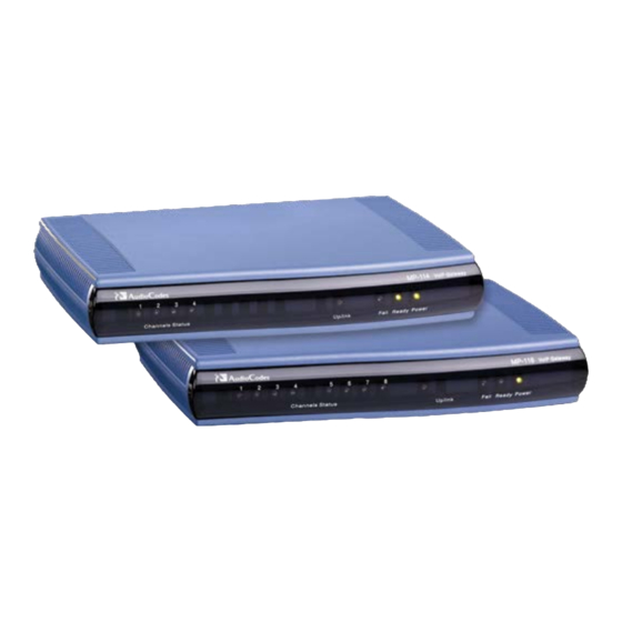
The device's front panel provides LEDs for indicating various operating statuses. The figure below displays the front panel of the MP-118. This is similar to the MP-114 and MP-112 models, differing only in the number of Channel Status LEDs (corresponding to the number of channels). -
Page 14: Table 3-2: Mp-11X Front-Panel Leds Description
(their resources are "borrowed" for SRTP functionality): Fast Green MP-112: Not applicable - SRTP does not Blinking affect channel capacity. MP-114: LED state applies to Channel Status 4 LED (i.e., Port 4 is unavailable for calls). -
Page 15: Rear Panel And Port Description
Ethernet 10/100Base-TX Uplink port. RS-232 RS-232 status port (requires a DB-9 to PS/2 adaptor). Note: MP-112 does not provide a serial port. FXS and/or FXO Provides two, four, or eight FXS/FXO ports (depending on MediaPack model). Note: MP-112 does not support FXO interfaces. - Page 16 MP-11x This page is intentionally left blank. Hardware Installation Manual Document #: LTRT-59824...
-
Page 17: Mounting Mp-11X
Hardware Installation Manual 4. Mounting MP-11x Mounting MP-11x The device can be mounted in one of the following ways: Desktop mounting - see 'Desktop Mounting' on page Wall mounting - see 'Wall Mounting' on page Standard 19-inch rack mounting - see '19-inch Rack Mounting' on page The figure below shows the mounting components on the underside of MP-11x: Figure 4-1: MP-11x Underside Table 4-1: Mounting Components on MP-11x Underside... -
Page 18: Desktop Mounting
MP-11x Desktop Mounting Attach the four (supplied) anti-slide bumpers to the base of MP-11x and place it on a desktop in the desired position. Desktop Mount Safety Instructions When mounting the chassis on a desktop, adhere to the following safety instructions: •... -
Page 19: Figure 4-3: Protruded Screw Distance From Wall Surface
Hardware Installation Manual 4. Mounting MP-11x Insert a wall anchor of the appropriate size into each hole. Fasten a DIN 96 3.5 x 20 wood screws (not supplied) into each of the wall anchors. Make sure that the heads extend sufficiently (about 3/16 inch or 5 mm) from the wall for the device's keyholes to hang on: Figure 4-3: Protruded Screw Distance from Wall Surface Mount the device on the wall by hanging the device's keyholes on the screw heads. -
Page 20: 19-Inch Rack Mounting
MP-11x 19-inch Rack Mounting MP-11x can be installed in a standard 19-inch rack by placing it on an AudioCodes' 19-inch rack-mounting shelf (special customer order) that must be pre-installed in a rack. The shelf can hold up to two MP-11x devices. The rack-mounting shelf can be ordered separately from AudioCodes. -
Page 21: Figure 4-5: Mp-11X Rack Mount Installation
Hardware Installation Manual 4. Mounting MP-11x To install MP-11x in a 19-inch rack: Attach one or two MP-11x devices to the shelf using the shelf-to-device screws (supplied). Position the shelf in the rack and align its side holes with the rack frame holes. Attach the shelf to the rack using four standard rack screws (not supplied). - Page 22 MP-11x This page is intentionally left blank. Hardware Installation Manual Document #: LTRT-59824...
-
Page 23: Cabling Mp-11X
Hardware Installation Manual 5. Cabling MP-11x Cabling MP-11x This section describes the MP-11x cabling procedures: To cable MP-11x: Power Surge Protection and Grounding – see 'Power Surge Protection and Grounding' on page Connecting to the Ethernet network – see 'Connecting MP-11x to the Network' on page ... -
Page 24: Figure 5-1: Power Surge Protection
MP-11x. When done correctly, the installation will meet ITU-T K.21 basic level. • As most of the installation is the responsibility of the customer, AudioCodes can assume responsibility for damage only if the customer can establish that MP-11x does not comply with the standards specified above (and MP-11x is within the hardware warranty period). -
Page 25: Connecting Mp-11X To The Ethernet Network
Hardware Installation Manual 5. Cabling MP-11x Connecting MP-11x to the Ethernet Network The procedure below describes how to connect MP-11x directly to the Ethernet network. Cable specifications: Cable: Crossover Ethernet cable Connector: RJ-45 Connector Pinouts: Figure 5-2: RJ-45 Connector Pinouts for Ethernet Connection ... -
Page 26: Connecting Mp-11X To Fxs Interfaces
If SRTP is enabled, the device "borrows" resources (DSPs) for this functionality from other ports, making these ports unavailable for calls: √ MP-112: Not applicable - SRTP does not affect channel capacity. √ MP-114: Port 4 is unavailable for calls. -
Page 27: Connecting Mp-11X To Fxo Interfaces
Hardware Installation Manual 5. Cabling MP-11x Connecting MP-11x to FXO Interfaces The procedure below describes how to cable the MP-11x FXO interfaces. Warnings for FXO Port Interfaces: • The device does not include primary telecom protection! Additional protection (usually a 350V 3-pin Gas Arrestor as described in ITU-T K.44) must be provided at the entry point of the telecom wires into the building (usually on the main distribution frame or MDF), in conjunction with proper grounding. -
Page 28: Figure 5-7: Connecting Fxo Interfaces
MP-11x To connect MP-11x to FXO devices: Connect one end of an RJ-11 cable to the desired FXO port (labeled FXO). Figure 5-7: Connecting FXO Interfaces Connect the other end of the cable to the required telephone interface (e.g., telephone exchange analog lines or PBX extensions). -
Page 29: Connecting Mp-11X To Analog Fxs Lifeline Phone
For devices providing only FXO ports: A Lifeline is not available. Notes: • The Lifeline feature is not supported by MP-112. • The use of the Lifeline upon network failure can be disabled using the LifeLineType ini file parameter (described in the User's Manual). -
Page 30: Figure 5-9: Lifeline Cabling (Using Splitter Cable) For Fxs-Only Devices
MP-11x To cable the MP-11x FXS Lifeline: Connect the Lifeline splitter to Port #1 on MP-11x (the Lifeline splitter is a special order option). Connect the Lifeline phone to Port A on the Lifeline splitter. Connect an analog PSTN line to Port B on the Lifeline splitter. Figure 5-9: Lifeline Cabling (Using Splitter Cable) for FXS-Only Devices ... -
Page 31: Connecting Mp-11X To Computer For Serial Communication
Figure 5-12: PS/2 Connector Pinouts Notes: • This procedure is not applicable to MP-112 as this model does not provide an RS- 232 serial interface port. • The PS/2 to DB-9 cable adaptor is not included in the MP-11x package. -
Page 32: Connecting Mp-11X To Power
Description Input Ratings 100-240 VAC, 50-60 Hz, 0.3A max Max. Power Consumption Model Value MP-112 MP-114 with 2 x FXS / 2 x FXO MP-114 with 4 x FXO 4.9W MP-114 with 4 x FXS MP-118 with 8 x FXS 24.5W... -
Page 33: Figure 5-14: Connecting To The Power Supply
Hardware Installation Manual 5. Cabling MP-11x To connect MP-11x to the power supply: Connect the line socket of the AC power cord (supplied) to the device's AC power socket (labeled 100-240V 0.3A ~50-60 Hz), located on the rear panel. Figure 5-14: Connecting to the Power Supply Connect the plug at the other end of the AC power cord to a standard electrical outlet. - Page 34 International Headquarters AudioCodes Inc. 1 Hayarden Street, 27 World’s Fair Drive, Airport City Somerset, NJ 08873 Lod 7019900, Israel Tel: +1-732-469-0880 Tel: +972-3-976-4000 Fax: +1-732-469-2298 Fax: +972-3-976-4040 Contact us: www.audiocodes.com/info Website: www.audiocodes.com Document #: LTRT-59824...
Need help?
Do you have a question about the MP-112 and is the answer not in the manual?
Questions and answers