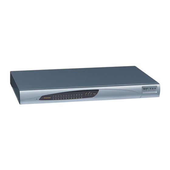
AudioCodes MediaPack MP-102 User Manual
Mediapack series analog voip gateways
Hide thumbs
Also See for MediaPack MP-102:
- User manual (158 pages) ,
- Installation manual (48 pages) ,
- User manual (20 pages)
Table of Contents
Advertisement
Advertisement
Table of Contents

Related Manuals for AudioCodes MediaPack MP-102


Summary of Contents for AudioCodes MediaPack MP-102
- Page 1 MP-1xx SIP User’s Manual Version 4.4 Document #: LTRT-65404...
- Page 2 Notice This document describes the AudioCodes MediaPack Series MP-1xx Voice over IP (VoIP) gateways. Information contained in this document is believed to be accurate and reliable at the time of printing. However, due to ongoing product improvements and revisions, AudioCodes cannot guarantee accuracy of printed material after the Date Published nor can it accept responsibility for errors or omissions.
-
Page 3: Table Of Contents
MP-1xx SIP User’s Manual Contents Table of Contents Overview ........................15 Introduction .............................15 Gateway Description........................15 SIP Overview ..........................17 MP-1xx Features ..........................18 1.4.1 General Features ........................18 1.4.2 Hardware Features .........................18 1.4.3 SIP Features ...........................18 MP-1xx Physical Description..................21 MP-1xx Front Panel ........................21 2.1.1 MP-1xx Front Panel Buttons ....................21 2.1.2 MP-1xx Front Panel LEDs ......................22... - Page 4 MP-1xx SIP 5.8.2 Configuring the Advanced Parameters...................58 5.8.2.1 General Parameters .....................58 5.8.2.2 Supplementary Services....................63 5.8.2.3 Keypad Features ......................66 5.8.3 Configuring the Number Manipulation Tables ................68 5.8.3.1 Dialing Plan Notation ....................71 5.8.4 Configuring the Routing Tables ....................73 5.8.4.1 General Parameters .....................73 5.8.4.2 Tel to IP Routing Table ....................75 5.8.4.3...
- Page 5 MP-1xx SIP User’s Manual Contents Prerecorded Tones (PRT) File .....................147 7.2.1 PRT File Format........................147 The Coefficient Configuration File ....................148 Gateway Capabilities Description ................149 Proxy or Registrar Registration Example ..................149 Configuring the DTMF Transport Types ..................150 Configuring the Gateway’s Alternative Routing (based on Connectivity and QoS)......152 8.3.1 Alternative Routing Mechanism ....................152 8.3.2...
- Page 6 11.6.4 Multiple SNMP Trap Destinations ..................188 11.6.4.1 Configuration via the ini File ..................188 11.6.4.2 Configuration via SNMP .....................189 11.7 SNMP Manager Backward Compatibility..................190 11.8 AudioCodes’ Element Management System ................190 12 Selected Technical Specifications ................. 191 Appendix A MP-1xx SIP Software Kit............... 195 Appendix B The BootP/TFTP Configuration Utility..........
- Page 7 MP-1xx SIP User’s Manual Contents E.1.1 Replacing the Main Corporate Logo with an Image File............213 E.1.2 Replacing the Main Corporate Logo with a Text String ............215 Replacing the Background Image File..................215 Customizing the Product Name....................216 Modifying ini File Parameters via the Web AdminPage ...............217 Appendix F Accessory Programs and Tools ............
- Page 8 Figure 1-1: MP-124 Gateway Front View ......................15 Figure 1-2: MP-108 Gateway Front View ......................16 Figure 1-3: MP-104 Gateway Front View ......................16 Figure 1-4: MP-102 Gateway Front View ......................16 Figure 1-5: Typical MP-1xx VoIP Application ....................17 Figure 2-1: MP-108 Front Panel ........................21 Figure 2-2: MP-124 Front Panel ........................21...
- Page 9 MP-1xx SIP User’s Manual Contents Figure 5-38: MP-1xx/FXS Channel Status Screen..................127 Figure 5-39: Channel Status Details Screen ....................128 Figure 5-40: Message Log Screen .........................129 Figure 5-41: System Information Screen......................130 Figure 5-42: Start Software Upgrade Screen ....................131 Figure 5-43: Load a cmp File Screen ......................132 Figure 5-44: cmp File Successfully Loaded into the MP-1xx Notification ............133 Figure 5-45: Load an ini File Screen ......................134 Figure 5-46: Load a CPT File Screen......................135...
- Page 10 MP-1xx SIP List of Tables Table 2-1: Front Panel Buttons on the MP-1xx ....................21 Table 2-2: Indicator LEDs on the MP-1xx Front Panel..................22 Table 2-3: MP-10x Rear Panel Component Descriptions ................23 Table 2-4: Indicator LEDs on the MP-10x Rear Panel ..................23 Table 2-5: MP-124 Rear Panel Component Descriptions ................24 Table 2-6: Indicator LEDs on the MP-124 Rear Panel ..................24 Table 3-1: Cables and Cabling Procedure .......................29...
- Page 11 MP-1xx SIP User’s Manual Contents Table C-3: Default RTP/RTCP/T.38 Port Allocation..................210 Table E-1: Customizable Logo ini File Parameters ..................215 Table E-2: Web Appearance Customizable ini File Parameters ..............215 Table E-3: Customizable Logo ini File Parameters ..................216 Table E-4: Web Appearance Customizable ini File Parameters ..............216 Table G-1: acBoardFatalError Alarm Trap .....................229 Table G-2: acBoardEvResettingBoard Alarm Trap ..................229 Table G-3: acBoardCallResourcesAlarm Alarm Trap ..................230...
-
Page 12: Customer Support
Trademarks AC logo, Ardito, AudioCoded, AudioCodes, AudioCodes logo, IPmedia, Mediant, MediaPack, MP- MLQ, NetCoder, Stretto, TrunkPack, VoicePacketizer and VoIPerfect, are trademarks or registered trademarks of AudioCodes Limited. All other products or trademarks are property of their respective owners. Customer Support Customer technical support and service are provided by AudioCodes’... -
Page 13: March
MP-1xx SIP User’s Manual General Ensure that you connect FXS ports to analog telephone or to PBX-trunk Warning: lines only and FXO ports to CO/PBX lines only. The MP-1xx is supplied as a sealed unit and must only be serviced by Warning: qualified service personnel. - Page 14 MP-1xx SIP Reader’s Notes MP-1xx SIP User’s Manual Document #: LTRT-65404...
-
Page 15: Overview
This document provides you with the information on installation, configuration and operation of the MP-124 24-port, MP-108 8-port, MP-104 4-port and MP-102 2-port VoIP media gateways. As these units have similar functionality, except for the number of channels and some minor features, they are referred to collectively as the MP-1xx. -
Page 16: Figure 1-2: Mp-108 Gateway Front View
The MP-104 supports up to 4 analog telephone loop start FXS or FXO ports, shown in Figure 1-3. Figure 1-3: MP-104 Gateway Front View The MP-102 supports up to 2 analog telephone loop start FXS ports, shown in Figure 1-4. Figure 1-4: MP-102 Gateway Front View MP-1xx SIP User’s Manual... -
Page 17: Sip Overview
MP-1xx SIP User’s Manual 1. Overview The layout diagram (Figure 1-5), illustrates a typical MP-108 and MP-104 or MP-102 VoIP application. Figure 1-5: Typical MP-1xx VoIP Application SIP Overview SIP (Session Initialization Protocol) is an application-layer control (signaling) protocol used on the MP-1xx for creating, modifying, and terminating sessions with one or more participants. -
Page 18: Mp-1Xx Features
MP-1xx SIP MP-1xx Features This section provides a high-level overview of some of the many MP-1xx supported features. 1.4.1 General Features • Superior, high quality Voice, Data and fax over IP networks. • Spans a range of 2 to 24 analog ports. •... - Page 19 MP-1xx SIP User’s Manual 1. Overview • Proxy and Registrar Authentication (handling 401 and 407 responses) using Basic or Digest methods. • Single gateway Registration or multiple Registration of all gateway endpoints. • Configuration of authentication username and password per each gateway endpoint, or single username and password per gateway.
- Page 20 MP-1xx SIP Reader’s Notes MP-1xx SIP User’s Manual Document #: LTRT-65404...
-
Page 21: Mp-1Xx Physical Description
25. MP-1xx Front Panel Figure 2-1 Figure 2-2 illustrate the front layout of the MP-108 (almost identical on MP-104 and MP-102) and MP-124 respectively. Refer to Section 2.1.1 for meaning of the front panel buttons; refer to Section 2.1.2 for functionality of the front panel LEDs. -
Page 22: Mp-1Xx Front Panel Leds
MP-1xx SIP 2.1.2 MP-1xx Front Panel LEDs Table 2-2 lists and describes the front panel LEDs on the MP-1xx. MP-1xx (FXS/FXO) media gateways feature almost identical front panel Note: LEDs; they only differ in the number of channel LEDs that correspond to the number of channels. -
Page 23: Rear Panel
MP-1xx SIP User’s Manual 2. MP-1xx Physical Description Figure 2-3: MP-104/FXS Rear Panel Connectors Table 2-3: MP-10x Rear Panel Component Descriptions Item # Label Component Description 100-250V ~ 1A AC power supply socket. 50-60 Hz Protective earthing screw (mandatory for all installations). Eth 1 10/100 Base-TX Ethernet connection. -
Page 24: Table 2-5: Mp-124 Rear Panel Component Descriptions
MP-1xx SIP Table 2-5: MP-124 Rear Panel Component Descriptions Item # Label Component Description Protective earthing screw (mandatory for all installations). 100-250 V~ AC power supply socket. 50 - 60 Hz 2A ANALOG LINES 1 –24 50-pin Telco for 1 to 24 analog lines. Data Cntrl Ready LED indicators (described in Table... -
Page 25: Installing The Mp-1Xx
Remove the MP-1xx gateway from the carton. Check that there is no equipment damage. Check, retain and process any documents. Notify AudioCodes or your local supplier of any damage or discrepancies. Retain any diskettes or CDs. Package Contents Ensure that in addition to the MP-1xx, the package contains: •... -
Page 26: Mounting The Mp-1Xx
MP-1xx SIP Mounting the MP-1xx The MP-1xx can be mounted on a desktop or on a wall (only MP-10x), or installed in a standard 19-inch rack. Refer to Section on page for cabling the MP-1xx. 3.3.1 Mounting the MP-1xx on a Desktop No brackets are required. -
Page 27: Installing The Mp-124 In A 19-Inch Rack
MP-1xx SIP User’s Manual 3. Installing the MP-1xx Swivel the bracket until the holes in the bracket line up with the two empty screw holes on the device. Use the screws found in the devices’ package to attach the short bracket to the side of the device. -
Page 28: Mounting The Mp-10X On A Wall
3.3.4 Mounting the MP-10x on a Wall The MP-10x is mounted on a wall by the addition of two short (equal-length) supplied brackets. The MP-102 with brackets for wall mount is shown in Figure 3-4. To mount the MP-10x on a wall, take these 7 steps: Remove the screw on the side of the device that is nearest the bottom and the front panel. -
Page 29: Cabling The Mp-1Xx
MP-1xx SIP User’s Manual 3. Installing the MP-1xx Cabling the MP-1xx Verify that you have the cables listed under column ‘Cable’ in Table 3-1 before beginning to cable the MP-1xx according to the column ‘Cabling Procedure’. For detailed information on the MP-1xx rear panel connectors, refer to Section on page 22. -
Page 30: Figure 3-5: Rj-45 Ethernet Connector Pinout
MP-1xx SIP Figure 3-5: RJ-45 Ethernet Connector Pinout RJ-45 Connector and Pinout 1 2 3 4 5 6 7 8 1 - Tx+ 4, 5, 7, 8 2 - Tx- 3 - Rx+ connected 6 - Rx- Figure 3-6: RJ-11 Phone Connector Pinout RJ-11 Connector and Pinout 1 2 3 4 Not connected... -
Page 31: Figure 3-9: Dc Power Supply On The Mp-124
MP-1xx SIP User’s Manual 3. Installing the MP-1xx Figure 3-9: DC Power Supply on the MP-124 Table 3-2: DC Power Supply on the MP-124 Component Descriptions Component Description Item # 2 screws for wire connection to the DC terminal block. 2 screws for connecting the DC terminal block to the MP-124 panel. -
Page 32: Connecting The Mp-1Xx Rs-232 Port To Your Pc
Lifeline phone even when the MP-1xx is not powered on or not connected to the network. With the MP-108/FXS and MP-104/FXS the Lifeline connection is provided on port #4 (refer to Figure 3-12). With the MP-102/FXS the Lifeline connection is provided on port #2. The MP-124 and MP-10x/FXO do NOT support the Lifeline. Note: The Lifeline’s Splitter connects pins #1 and #4 to another source of an FXS port, and pins #2 and... -
Page 33: Figure 3-12: Mp-104/Fxs Lifeline Setup
Connect the Lifeline Splitter to port 4 (on the MP-104/FXS or MP-108/FXS) or to port 2 (on the MP-102/FXS). Connect the Lifeline phone to Port A on the Lifeline Splitter. Connect an analog PSTN line to Port B on the Lifeline Splitter. - Page 34 MP-1xx SIP Reader’s Notes MP-1xx SIP User’s Manual Document #: LTRT-65404...
-
Page 35: Getting Started
MP-1xx SIP User’s Manual 4. Getting Started Getting Started The MP-1xx is supplied with application software already resident in its flash memory (with factory default parameters). Section below describes how to assign an IP address to the MP-1xx, while Section page describes how to set up the MP-1xx with basic parameters using a standard Web browser (such as Microsoft... -
Page 36: Assigning An Ip Address Using Bootp
MP-1xx SIP Click the Reset button and click OK in the prompt; the MP-1xx applies the changes and restarts. This takes approximately 1 minute to complete. When the MP-1xx has finished restarting, the Ready and LAN LEDs on the front panel are lit green. Record and retain the IP address and subnet mask you assign the MP-1xx. -
Page 37: Configure The Mp-1Xx Basic Parameters
MP-1xx SIP User’s Manual 4. Getting Started Reconnect the power cable; the gateway is powered up. After approximately 45 seconds the Ready LED turns to green and the Control LED blinks for about 3 seconds. While the Control LED is blinking, press shortly on the reset button (located on the left side of the front panel);... - Page 38 MP-1xx SIP Under ‘SIP Parameters’, enter the MP-1xx Domain Name in the field ‘Gateway Name’. If the field is not specified, the MP-1xx IP address is used instead (default). When working with a Proxy server, set ‘Working with Proxy’ field to ‘Yes’ and enter the IP address of the primary Proxy server in the field ‘Proxy IP Address’.
-
Page 39: Configuring The Mp-1Xx
141. • An SNMP browser software (refer to Section on page 179). • AudioCodes’ Element Management System (EMS) (refer to Section 11.8 on page and to AudioCodes’ EMS User’s Manual or EMS Product Description). To upgrade the MP-1xx (load new software or configuration files onto the gateway) use the Software Upgrade wizard, available through the Web Interface (refer to Section 5.11.1... -
Page 40: Password Control
MP-1xx SIP Password Control The Embedded Web Server is protected by a unique username and password combination. The first time a browser request is made, the User is requested to provide his username and password to obtain access. Subsequent requests are negotiated by the browser on behalf of the User, so that the User doesn’t have to re-enter the username and password for each request, but the request is still authenticated (the Embedded Web Server uses the MD5 authentication method supported by the HTTP 1.1 protocol). -
Page 41: Accessing The Embedded Web Server
MP-1xx SIP User’s Manual 5. Configuring the MP-1xx Accessing the Embedded Web Server To access the Embedded Web Server, take these 4 steps: Open a standard Web-browsing application such as Microsoft™ Internet Explorer™ (Version 6.0 and higher) or Netscape™ Navigator™ (Version 7.0 and higher). In the Uniform Resource Locator (URL) field, specify the IP address of the MP-1xx (e.g., http://10.1.10.10);... -
Page 42: Getting Acquainted With The Web Interface
• Main action frame - the main area of the screen in which information is viewed and configured. • Corporate logo – AudioCodes’ corporate logo. For information on how to remove this logo Appendix E on page 213. • Control Protocol – the MP-1xx control protocol. -
Page 43: Saving Changes
MP-1xx SIP User’s Manual 5. Configuring the MP-1xx • Advanced Configuration – Use this subdivided menu to set the gateway’s advanced configuration parameters (for advanced users only) (refer to Section on page 103). • Status & Diagnostics – Use this subdivided menu to view and monitor the gateway’s channels, Syslog messages, hardware / software product information, and to assess the gateway’s statistics and IP connectivity information (refer to Section 5.10... -
Page 44: Protocol Management
MP-1xx SIP Protocol Management Use this subdivided menu to configure the gateway’s SIP parameters and tables. Those parameters contained within square brackets are the names used to Note: configure the parameters via the ini file. 5.8.1 Protocol Definition Parameters Use this submenu to configure the gateway’s specific SIP protocol parameters. 5.8.1.1 General Parameters Use this screen to configure general SIP parameters. -
Page 45: Table 5-1: Protocol Definition, General Parameters (Continues On Pages 45 To 47)
MP-1xx SIP User’s Manual 5. Configuring the MP-1xx Configure the general parameters under Protocol Definition according to Table 5-1. Click the Submit button to save your changes. To save the changes so they are available after a power fail refer to Section 5.12 on page 139. - Page 46 MP-1xx SIP Table 5-1: Protocol Definition, General Parameters (continues on pages 45 to 47) Parameter Description Asserted Identity Mode Disable [0] = None (default). Adding PAsserted Identity [1]. [AssertedIdMode] Adding PPrefered Identity [2]. The Asserted ID mode defines the header that is used in the generated INVITE request. The header also depends on the calling Privacy: allowed or restricted.
- Page 47 MP-1xx SIP User’s Manual 5. Configuring the MP-1xx Table 5-1: Protocol Definition, General Parameters (continues on pages 45 to 47) Parameter Description Play Ringback Tone to IP Don’t Play [0] = Ringback tone isn’t played to the IP side of the call (default). Play [1] = Ringback tone is played to the IP side of the call after SIP 183 [PlayRBTone2IP]...
-
Page 48: Proxy & Registration Parameters
MP-1xx SIP 5.8.1.2 Proxy & Registration Parameters Use this screen to configure parameters that are associated with Proxy and Registration. To configure the Proxy & Registration parameters, take these 4 steps: Open the ‘Proxy & Registration’ parameters screen (Protocol Management menu > Protocol Definition submenu >... -
Page 49: Table 5-2: Proxy & Registration Parameters (Continues On Pages 49 To 52)
MP-1xx SIP User’s Manual 5. Configuring the MP-1xx Configure the Proxy & Registration parameters according to Table 5-2. Click the Submit button to save your changes, or click the Register or Un-Register buttons to save your changes and to register / unregister to a Proxy / Registrar. To save the changes so they are available after a power fail refer to Section 5.12 on page... - Page 50 MP-1xx SIP Table 5-2: Proxy & Registration Parameters (continues on pages 49 to 52) Parameter Description Second Redundant Proxy IP addresses of the second redundant Proxy you are using. IP Address Enter the IP address as FQDN or in dotted format notation (for example 192.10.1.255). You can also specify the selected port in the format: <IP Address>:<port>.
- Page 51 MP-1xx SIP User’s Manual 5. Configuring the MP-1xx Table 5-2: Proxy & Registration Parameters (continues on pages 49 to 52) Parameter Description Re-registration Timing (%) Defines the re-registration timing (in percentage). The timing is a percentage of the re- [RegistrationTimeDivider] register timing set by the Registration server.
- Page 52 MP-1xx SIP Table 5-2: Proxy & Registration Parameters (continues on pages 49 to 52) Parameter Description Number of RTX Before Hot- Number of retransmitted Invite messages before call is routed (hot swapped) to another Swap Proxy. The range is 1-30. The default is 3. [ProxyHotSwapRtx] Note: This parameter is also used for alternative routing using the Tel to IP Routing table.
-
Page 53: Coders
MP-1xx SIP User’s Manual 5. Configuring the MP-1xx 5.8.1.3 Coders From the Coders screen you can configure the first to fifth preferred coders (and their corresponding ptimes) for the gateway. The first coder is the highest priority coder and is used by the gateway whenever possible. -
Page 54: Table 5-3: Ini File Coder Parameter
MP-1xx SIP Table 5-3: ini File Coder Parameter Parameter Description Enter the coders in the format: CoderName=<Coder>,<ptime>. CoderName For example: CoderName = g711Alaw64k,20 CoderName = g711Ulaw64k,40 CoderName = g7231,90 Note 1: This parameter (CoderName) can appear up to 10 times. Note 2: The coder name is case-sensitive. -
Page 55: Dtmf & Dialing Parameters
MP-1xx SIP User’s Manual 5. Configuring the MP-1xx 5.8.1.4 DTMF & Dialing Parameters Use this screen to configure parameters that are associated with DTMF and dialing. To configure the dialing parameters, take these 4 steps: Open the ‘DTMF & Dialing’ screen (Protocol Management menu > Protocol Definition submenu >... - Page 56 MP-1xx SIP Table 5-4: DTMF & Dialing Parameters (continues on pages 55 to 57) Parameter Description Use Out-of-Band DTMF Use out-of-band signaling to relay DTMF digits. [0] = DTMF digits are sent in-band (default). [IsDTMFUsed] [1] = DTMF digits are sent out-of-band according to the parameter ‘Out-of-band DTMF format’.
- Page 57 MP-1xx SIP User’s Manual 5. Configuring the MP-1xx Table 5-4: DTMF & Dialing Parameters (continues on pages 55 to 57) Parameter Description Digit Mapping Rules Digit map pattern. If the digit string (dialed number) has matched one of the patterns in the digit map, the gateway stops collecting digits and starts to establish a call with the [DigitMapping] collected number...
-
Page 58: Configuring The Advanced Parameters
MP-1xx SIP 5.8.2 Configuring the Advanced Parameters Use this submenu to configure the gateway’s advanced control protocol parameters. 5.8.2.1 General Parameters Use this screen to configure general control protocol parameters. To configure the general parameters under Advanced Parameters, take these 4 steps: Open the ‘General Parameters’... -
Page 59: Table 5-5: Advanced Parameters, General Parameters (Continues On Pages 59 To 62)
MP-1xx SIP User’s Manual 5. Configuring the MP-1xx Configure the general parameters under ‘Advanced Parameters’ according to Table 5-5. Click the Submit button to save your changes. To save the changes so they are available after a power fail refer to Section 5.12 on page 139. - Page 60 MP-1xx SIP Table 5-5: Advanced Parameters, General Parameters (continues on pages 59 to 62) Parameter Description Enable DID Wink Disable [0] = DID is disabled (default). Enable [1] = Enable DID. [EnableDIDWink] If enabled, the MP-1xx can be used for connection to EIA/TIA-464B DID Loop Start lines.
- Page 61 MP-1xx SIP User’s Manual 5. Configuring the MP-1xx Table 5-5: Advanced Parameters, General Parameters (continues on pages 59 to 62) Parameter Description Silence Detection Method Silence detection method. None [0] = Silence detection option is disabled. [FarEndDisconnectSilenceM Packets Count [1] = According to packet count. ethod] Voice/Energy Detectors [2] = According to energy and voice detectors (default).
- Page 62 MP-1xx SIP Table 5-5: Advanced Parameters, General Parameters (continues on pages 59 to 62) Parameter Description Max Number of Active Calls Defines the maximum number of calls that the gateway can have active at the same time. If the maximum number of calls is reached, new calls are not established. [MaxActiveCalls] The default value is max available channels (no restriction on the maximum number of calls).
-
Page 63: Supplementary Services
MP-1xx SIP User’s Manual 5. Configuring the MP-1xx 5.8.2.2 Supplementary Services Use this screen to configure parameters that are associated with supplementary services. For detailed information on the supplementary services, refer to Section on page 153. To configure the supplementary services’ parameters, take these 4 steps: Open the ‘Supplementary Services’... -
Page 64: Table 5-6: Supplementary Services Parameters (Continues On Pages 64 To 65)
MP-1xx SIP Table 5-6: Supplementary Services Parameters (continues on pages 64 to 65) Parameter Description Enable Hold [0] = Disable the Hold service (default). [1] = Enable the Hold service. [EnableHold] If the Hold service is enabled, a user can activate Hold (or Unhold) using the hook-flash. On receiving a Hold request, the remote party is put on-hold and hears the hold tone. - Page 65 MP-1xx SIP User’s Manual 5. Configuring the MP-1xx Table 5-6: Supplementary Services Parameters (continues on pages 64 to 65) Parameter Description Enable Caller ID [0] = Disable the Caller ID service (default). [1] = Enable the Caller ID service. [EnableCallerID] If the Caller ID service is enabled, then, for FXS gateways, calling number and Display text are sent to gateway port.
-
Page 66: Keypad Features
MP-1xx SIP 5.8.2.3 Keypad Features The Keypad Features screen (applicable only to FXS gateways) enables you to activate / deactivate the following features directly from the connected telephone’s keypad: • Call Forward (refer to Section 5.8.8.4 on page 96). • Caller ID Restriction (refer to Section 5.8.8.3 on page 95). -
Page 67: Table 5-7: Keypad Features Parameters
MP-1xx SIP User’s Manual 5. Configuring the MP-1xx Table 5-7: Keypad Features Parameters Parameter Description Forward Unconditional Keypad sequence that activates the immediate forward option. [KeyCFUnCond] No Answer Keypad sequence that activates the forward on no answer option. [KeyCFNoAnswer] On Busy Keypad sequence that activates the forward on busy option. -
Page 68: Configuring The Number Manipulation Tables
MP-1xx SIP 5.8.3 Configuring the Number Manipulation Tables The VoIP gateway provides four Number Manipulation tables for incoming and outgoing calls. These tables are used to modify the destination and source telephone numbers so that the calls can be routed correctly. The Manipulation Tables are: •... -
Page 69: Table 5-8: Number Manipulation Parameters
MP-1xx SIP User’s Manual 5. Configuring the MP-1xx Click the Submit button to save your changes. To save the changes so they are available after a power fail refer to Section 5.12 on page 139. Table 5-8: Number Manipulation Parameters Parameter Description Destination Prefix... -
Page 70: Table 5-9: Number Manipulation Ini File Parameters (Continues On Pages 70 To 71)
MP-1xx SIP Table 5-9: Number Manipulation ini File Parameters (continues on pages 70 to 71) Parameter Description Manipulates the destination number for Tel to IP calls. NumberMapTel2IP NumberMapTel2IP = a,b,c,d,e,f,g a = Destination number prefix b = Number of stripped digits from the left, or (if brackets are used) from the right. A combination of both options is allowed. -
Page 71: Dialing Plan Notation
MP-1xx SIP User’s Manual 5. Configuring the MP-1xx Parameter Description SourceNumberMapTel2IP = a,b,c,d,e,f,g,h SourceNumberMapTel2IP a = Source number prefix b = Number of stripped digits from the left, or (if in brackets are used) from right. A combination of both options is allowed. c = String to add as prefix, or (if in brackets are used) as suffix. - Page 72 MP-1xx SIP • [5551200-5551300]# represents all numbers from 5551200 to 5551300 • [2,3,4] represents all numbers that start with the numbers 2, 3 and 4 • 54324 represents any number that starts with 54324 • 54324xx# represents a 7 digit number that starts with 54324 •...
-
Page 73: Configuring The Routing Tables
MP-1xx SIP User’s Manual 5. Configuring the MP-1xx 5.8.4 Configuring the Routing Tables Use this submenu to configure the gateway’s IP Tel and Tel IP routing tables and their associated parameters. 5.8.4.1 General Parameters Use this screen to configure the gateway’s IP Tel and Tel IP routing parameters. To configure the general parameters under Routing Tables, take these 4 steps: Open the ‘General Parameters’... - Page 74 MP-1xx SIP Table 5-10: Routing Tables, General Parameters (continues on pages 73 to 74) Parameter Description IP to Tel Remove Routing [0] = Don't remove prefix (default) Table Prefix [1] = Remove the prefix (defined in the IP to Hunt Group Routing table) from a telephone number for an IP Tel call, before forwarding it to Tel.
-
Page 75: Tel To Ip Routing Table
MP-1xx SIP User’s Manual 5. Configuring the MP-1xx 5.8.4.2 Tel to IP Routing Table The Tel to IP Routing Table is used to route incoming Tel calls to IP addresses. This routing table associates a called / calling telephone number’s prefixes with a destination IP address or with an FQDN (Fully Qualified Domain Name). -
Page 76: Figure 5-12: Tel To Ip Routing Table Screen
MP-1xx SIP Tel to IP routing can be performed either before or after applying the number Tip: manipulation rules. To control when number manipulation is done, set the Tel to IP Routing Mode parameter (described in Table 5-11). To configure the Tel to IP Routing table, take these 6 steps: Open the ‘Tel to IP Routing’... - Page 77 MP-1xx SIP User’s Manual 5. Configuring the MP-1xx Table 5-11: Tel to IP Routing Table Parameter Description Destination IP Address In each of the IP Address fields, enter the IP address that is assigned to these prefixes. Domain names, such as domain.com, can be used instead of IP addresses. To discard outgoing IP calls, enter 0.0.0.0 in this field.
-
Page 78: Ip To Hunt Group Routing
MP-1xx SIP 5.8.4.3 IP to Hunt Group Routing The IP to Hunt Group Routing Table is used to route incoming IP calls to groups of channels called hunt groups. Calls are assigned to hunt groups according to any combination of the following three options (or using each independently): •... -
Page 79: Table 5-12: Ip To Hunt Group Routing Table
MP-1xx SIP User’s Manual 5. Configuring the MP-1xx In the ‘IP to Tel Routing Mode’ field, select the IP to Tel routing mode (refer to Table 5-12). In the ‘Routing Index’ drop-down list, select the range of entries that you want to edit (up to 24 entries can be configured). -
Page 80: Internal Dns Table
MP-1xx SIP 5.8.4.4 Internal DNS Table The internal DNS table, similar to a DNS resolution, translates hostnames into IP addresses. This table is used when hostname translation is required (e.g., ‘Tel to IP Routing’ table, etc.). Two different IP addresses can be assigned to the same hostname. If the hostname isn’t found in this table, the gateway communicates with an external DNS server. -
Page 81: Reasons For Alternative Routing
MP-1xx SIP User’s Manual 5. Configuring the MP-1xx 5.8.4.5 Reasons for Alternative Routing The Reasons for Alternative Routing screen includes two tables (Tel IP and IP Tel). Each table enables you to define up to 4 different release reasons. If a call is released as a result of one of these reasons, the gateway tries to find an alternative route to that call. -
Page 82: Table 5-14: Reasons For Alternative Routing Ini File Parameter
MP-1xx SIP Table 5-14: Reasons for Alternative Routing ini File Parameter Parameter Name in ini File Parameter Format AltRouteCauseTel2IP = <SIP Call failure reason from IP> AltRouteCauseTel2IP For example: AltRouteCauseTel2IP = 408 (Response timeout). AltRouteCauseTel2IP = 486 (User is busy). Note: This parameter can appear up to 4 times. -
Page 83: Configuring The Profile Definitions
MP-1xx SIP User’s Manual 5. Configuring the MP-1xx 5.8.5 Configuring the Profile Definitions Utilizing the Profiles feature, the MP-1xx provides high-level adaptation when connected to a variety of equipment (from both Tel and IP sides) and protocols, each of which require a different system behavior. -
Page 84: Table 5-15: Ini File Coder Group Parameters
MP-1xx SIP many coder payloads are combined into one RTP (voice) packet. Note 1: The ptime packetization period depends on the selected coder name. Note 2: If not specified, the ptime gets a default value. Note 3: The ptime specifies the maximum packetization time the gateway can receive. Repeat steps 3 and 4 for the second to fifth coders (optional). -
Page 85: Tel Profile Settings
MP-1xx SIP User’s Manual 5. Configuring the MP-1xx 5.8.5.2 Tel Profile Settings Use the Tel Profile Settings screen to define up to four different Tel Profiles. These Profiles are used in the ‘Endpoint Phone Number’ table to associate different Profiles to gateway’s endpoints, thereby applying different behavior to different MP-1xx ports. -
Page 86: Table 5-16: Ini File Tel Profile Settings
MP-1xx SIP Configure the Profile’s parameters according to your requirements. For detailed information on each parameter refer to the description of the screen in which it is configured as an individual parameter. In the ‘Coder Group’ drop-down list, select the coder group you want to assign to that Profile. You can select the gateway’s default coders (refer to Section 5.8.1.3 on page 53) or one of... -
Page 87: Ip Profile Settings
MP-1xx SIP User’s Manual 5. Configuring the MP-1xx 5.8.5.3 IP Profile Settings Use the IP Profile Settings screen to define up to four different IP Profiles. These Profiles are used in the Tel to IP and IP to Hunt Group Routing tables to associate different Profiles to routing rules. -
Page 88: Table 5-17: Ini File Ip Profile Settings
MP-1xx SIP Repeat steps 2 to 6 for the second to fifth IP Profiles (optional). Click the Submit button to save your changes. To save the changes so they are available after a power fail refer to Section 5.12 on page 139. -
Page 89: Configuring The Endpoint Phone Numbers
MP-1xx SIP User’s Manual 5. Configuring the MP-1xx 5.8.6 Configuring the Endpoint Phone Numbers From the Endpoint Phone Numbers screen you can enable and assign telephone numbers, hunt groups (optional) and profiles to the VoIP gateway ports. To configure the Endpoint Phone Numbers table, take these 4 steps: Open the ‘Endpoint Phone Numbers Table’... - Page 90 Example: “Channel2Phone = 0, 1002” Appears once for each channel: 8 times for MP-108, or 4 times for MP-104 and twice for MP-102. For 8-port and 24-port gateways it is suggested to use “TrunkGroup“ parameter, where in a single line, all gateway’s phone numbers can be defined.
-
Page 91: Configuring The Hunt Group Settings
MP-1xx SIP User’s Manual 5. Configuring the MP-1xx 5.8.7 Configuring the Hunt Group Settings The Hunt Group Settings Table is used to determine the method in which new calls are assigned to channels within each hunt group. If such a rule doesn’t exist (for a specific hunt group), the global rule, defined by the Channel Select Mode parameter (Protocol Definition >... -
Page 92: Table 5-19: Channel Select Modes
MP-1xx SIP Table 5-19: Channel Select Modes Mode Description By phone number Select the gateway port according to the called number (refer to the note below). Cyclic Ascending Select the next available channel in ascending cycle order. Always select the next higher channel number in the hunt group. -
Page 93: Configuring The Endpoint Settings
MP-1xx SIP User’s Manual 5. Configuring the MP-1xx 5.8.8 Configuring the Endpoint Settings The Endpoint Settings screens enable you to configure port-specific parameters. 5.8.8.1 Authentication The Authentication Table (normally used with FXS gateways) defines a username and password combination for authentication for each MP-1xx port. The ‘Authentication Mode’... -
Page 94: Automatic Dialing
MP-1xx SIP 5.8.8.2 Automatic Dialing Use the Automatic Dialing Table to define telephone numbers that are automatically dialed when a specific port is used. To configure the Automatic Dialing table, take these 6 steps: Open the ‘Automatic Dialing’ screen (Protocol Management menu > Endpoint Settings submenu >... -
Page 95: Caller Id
MP-1xx SIP User’s Manual 5. Configuring the MP-1xx Table 5-21: Automatic Dialing ini File Parameter Parameter Name in ini File Parameter Format TargetOfChannel<Port> = <Phone>,<Mode> TargetOfChannelX For example: TargetOfChannel0 = 1001,1 TargetOfChannel3 = 911,2 Note 1: The numbering of channels starts with 0. Note 2: Define this parameter for each gateway port you want to use for Automatic Dialing. -
Page 96: Call Forward
MP-1xx SIP In the ‘Presentation’ field, select ‘Allowed’ [0] to send the string in the Caller ID/Name field when a (Tel IP) call is made using this VoIP gateway port. Select ‘Restricted’ [1] if you don’t want to send this string. Note that when ‘Presentation’ is set to ‘Restricted’, the parameter ‘Asserted Identity Mode’... -
Page 97: Table 5-23: Call Forward Table
MP-1xx SIP User’s Manual 5. Configuring the MP-1xx Configure the Call Forward parameters for each port according to the table below. Click the Submit button to save your changes. To save the changes so they are available after a power fail refer to Section 5.12 on page 139. -
Page 98: Caller Id Permissions
MP-1xx SIP 5.8.8.5 Caller ID Permissions The Caller ID Permission table is used to enable or disable (per port) the Caller ID generation (for FXS gateways) and detection (for FXO gateways). If a port isn’t configured, its Caller ID generation / detection are determined according to the global parameter ‘EnableCallerID’ (described in Table 5-6). -
Page 99: Configuring The Fxo Parameters
MP-1xx SIP User’s Manual 5. Configuring the MP-1xx 5.8.9 Configuring the FXO Parameters Use this screen to configure the gateway’s specific FXO parameters. To configure the FXO parameters, take these 4 steps: Open the ‘FXO Settings’ screen (Protocol Management menu > FXO); the ‘FXO Settings’ screen is displayed. - Page 100 MP-1xx SIP Table 5-25: FXO Parameters (continues on pages 99 to 100) Parameter Description Waiting For Dial Tone [0] = Don’t wait for dial tone. [1] = Wait for dial tone (default). [IsWaitForDialTone] Used for IP MP-1xx/FXO gateways, when ‘One Stage Dialing’ is enabled. If “wait for dial tone”...
-
Page 101: Protocol Management Ini File Parameters
MP-1xx SIP User’s Manual 5. Configuring the MP-1xx 5.8.10 Protocol Management ini File Parameters Table 5-26 describes the SIP Protocol Management parameters that can only be configured via the ini file. Table 5-26: Protocol Management, ini File Parameters (continues on pages 101 to 102) ini File Parameter Valid Range and Description Name... - Page 102 MP-1xx SIP Table 5-26: Protocol Management, ini File Parameters (continues on pages 101 to 102) ini File Parameter Valid Range and Description Name Defines the metering tone (12 kHz or 16 kHz) that is detected by FXO gateways and MeteringType generated by FXS gateways.
-
Page 103: Advanced Configuration
MP-1xx SIP User’s Manual 5. Configuring the MP-1xx Advanced Configuration Use this subdivided menu to set the gateway’s advanced configuration parameters (for advanced users only). 5.9.1 Configuring the Network Settings From the Network Settings page you can define: • IP settings. •... -
Page 104: Table 5-27: Network Setting Parameters (Continues On Pages 104 To 106)
MP-1xx SIP Configure the Network Settings according to Click the Submit button to save your changes. To save the changes so they are available after a power fail refer to Section 5.12 on page 139. Those parameters contained within square brackets are the names used to Note: configure the parameters via the ini file. - Page 105 MP-1xx SIP User’s Manual 5. Configuring the MP-1xx Table 5-27: Network Setting Parameters (continues on pages 104 to 106) Parameter Description Enable DHCP Disable [0] = Disable DHCP support on the gateway (default). Enable [1] = Enable DHCP support on the gateway. [DHCPEnable] After the gateway is powered up, it attempts to communicate with a BootP server.
- Page 106 MP-1xx SIP Table 5-27: Network Setting Parameters (continues on pages 104 to 106) Parameter Description Enable Syslog Enable [1] = Send the logs and error message generated by the gateway to the Syslog Server. If you select Enable, you must enter an IP address in the Syslog [EnableSyslog] Server IP address field.
-
Page 107: Configuring The Snmp Managers Table
MP-1xx SIP User’s Manual 5. Configuring the MP-1xx 5.9.1.1 Configuring the SNMP Managers Table The SNMP Managers table allows you to configure the attributes of up to five SNMP managers. To configure the SNMP Managers Table, take these 6 steps: Access the ‘Network Settings’... -
Page 108: Table 5-29: Board, Ini File Parameters (Continues On Pages 108 To 110)
MP-1xx SIP Trap Port Up to five parameters used to define the Port numbers of the remote SNMP Managers. The device sends SNMP traps to these ports. [SNMPManagerTrapPort_x] Note: The first entry (out of the five) replaces the obsolete parameter SNMPTrapPort. - Page 109 MP-1xx SIP User’s Manual 5. Configuring the MP-1xx Table 5-29: Board, ini File Parameters (continues on pages 108 to 110) ini File Parameter Name Valid Range and Description Enables / disables the Network Address Translation (NAT) mechanism. DisableNAT 0 = Enabled. 1 = Disabled (default).
- Page 110 MP-1xx SIP Table 5-29: Board, ini File Parameters (continues on pages 108 to 110) ini File Parameter Name Valid Range and Description The BootP parameters are special "Hidden" parameters. Once defined and saved in the flash memory, they are used even if they don't appear in the ini file.
-
Page 111: Table 5-30: Snmp Ini File Parameters
MP-1xx SIP User’s Manual 5. Configuring the MP-1xx Table 5-30 describes the SNMP parameters that can only be configured via the ini file. Table 5-30: SNMP ini File Parameters ini File Parameter Name Description The device’s local UDP port used for SNMP Get/Set commands. SNMPPort The range is 100 to 3999. -
Page 112: Multiple Routers Support
MP-1xx SIP 5.9.1.2 Multiple Routers Support Multiple routers support is designed to assist the media gateway when it operates in a multiple routers network. The gateway learns the network topology by responding to ICMP redirections and caches them as routing rules (with expiration time). When a set of routers operating within the same subnet serve as gateways to that network and intercommunicate using a dynamic routing protocol (such as OSPF, etc.), the routers can determine the shortest path to a certain destination and signal the remote host the existence of... -
Page 113: Configuring The Channel Settings
MP-1xx SIP User’s Manual 5. Configuring the MP-1xx 5.9.2 Configuring the Channel Settings The Channels Settings screen enables you to set the VoIP gateway channel parameters, such as Input and Output voice gain, Jitter buffer characteristics, Modem, Fax and DTMF transport modes. -
Page 114: Table 5-31: Channel Settings, Voice Settings Parameters
MP-1xx SIP Table 5-31: Channel Settings, Voice Settings Parameters Parameter Description Voice Volume Voice gain control in dB. This parameter sets the level for the transmitted (IP Tel) signal. [VoiceVolume] You can enter a value from -32 to 31 dB. The default value is 0 dB. -
Page 115: Figure 5-30: Channel Settings, Fax/Modem/Cid Parameters
MP-1xx SIP User’s Manual 5. Configuring the MP-1xx Figure 5-30: Channel Settings, Fax/Modem/CID Parameters Table 5-32: Channel Settings, Fax/Modem/CID Parameters (continues on pages 115 to 116) Parameter Description Fax Transport Mode Fax Transport Mode that the gateway uses. You can select: [FaxTransportMode] Disable [0]. - Page 116 MP-1xx SIP Table 5-32: Channel Settings, Fax/Modem/CID Parameters (continues on pages 115 to 116) Parameter Description V.23 Modem Transport Type V.23 Modem Transport Type that the gateway uses. You can select: [V23ModemTransportType] Transparent [0]. Relay [1] = N/A. Bypass [2] (default). V.32 Modem Transport Type V.32 Modem Transport Type that the gateway uses.
-
Page 117: Figure 5-31: Channel Settings, Rtp Parameters
MP-1xx SIP User’s Manual 5. Configuring the MP-1xx Figure 5-31: Channel Settings, RTP Parameters Table 5-33: Channel Settings, RTP Parameters Parameter Description Dynamic Jitter Buffer Minimum Delay Minimum delay for the Dynamic Jitter Buffer. You can enter a value from 0 to 150 milliseconds. [DJBufMinDelay] The default delay is 70 milliseconds. -
Page 118: Figure 5-32: Channel Settings, Miscellaneous Parameters
MP-1xx SIP Table 5-33: Channel Settings, RTP Parameters Parameter Description Enable RFC 3389 CN Payload Type Disable [0] = G.711 SID packets are sent in a proprietary method (default). Enable [1] = SID (comfort noise) packets are sent with the RTP SID payload [EnableStandardSIDPayloadType] type according to RFC 3389. -
Page 119: Table 5-35: Channel Settings, Ini File Parameters
‘FaxModemBypassCoderType’. The payload type used with these G.711 coders is a standard one (8 for G.711 A-Law and 0 for G.711 µ-Law). The parameters defining payload type for the “old” AudioCodes’ Bypass mode. ‘FaxBypassPayloadType’ and ‘ModemBypassPayloadType’ are not used with NSE Bypass. -
Page 120: Dynamic Jitter Buffer Operation
MP-1xx SIP Table 5-35: Channel Settings, ini File Parameters ini File Parameter Valid Range and Description Name 0 = There isn’t a Cisco gateway at the remote side (default). IsCiscoSCEMode 1 = There is a Cisco gateway at the remote side. When there is a Cisco gateway at the remote side, the local gateway must set the value of the “annexb”... -
Page 121: Restoring And Backing Up The Gateway Configuration
MP-1xx SIP User’s Manual 5. Configuring the MP-1xx 5.9.3 Restoring and Backing up the Gateway Configuration The Configuration File screen enables you to restore (load a new ini file to the gateway) or to back up (make a copy of the VoIP gateway ini file and store it in a directory on your computer) the current configuration the gateway is using. -
Page 122: Regional Settings
MP-1xx SIP 5.9.4 Regional Settings The ‘Regional Settings’ screen enables you to set and view the gateway’s internal date and time and to load to the gateway the following configuration files: Call Progress Tones, coefficient (different files for MP-1xx/FXS and MP-10x/FXO gateways) and Voice Prompts (currently not applicable to MP-1xx gateways). -
Page 123: Changing The Mp-1Xx Username And Password
MP-1xx SIP User’s Manual 5. Configuring the MP-1xx Saving a configuration file to flash memory may disrupt traffic on the MP-1xx. Note 1: To avoid this, disable all traffic on the device before saving to flash memory. A device reset is required to activate a loaded CPT file. Note 2: To save the loaded auxiliary files so they are available after a power fail refer to Section 5.12... -
Page 124: Status & Diagnostics
MP-1xx SIP 5.10 Status & Diagnostics Use this subdivided menu to view and monitor the gateway’s channels, Syslog messages, hardware / software product information, and to assess the gateway’s statistics and IP connectivity information. 5.10.1 Gateway Statistics Use the screens under Gateway Statistics to monitor real-time activity such as IP Connectivity information, call details and call statistics, including the number of call attempts, failed calls, fax calls, etc. -
Page 125: Call Counters
MP-1xx SIP User’s Manual 5. Configuring the MP-1xx Table 5-36: IP Connectivity Parameters Column Name Description IP address defined in the destination IP address field in the Tel to IP Routing table. IP Address IP address that is resolved from the host name defined in the destination IP address field in the Tel to IP Routing table. -
Page 126: Figure 5-37: Tel Ip Call Counters Screen
MP-1xx SIP Figure 5-37: Tel IP Call Counters Screen Table 5-37: Call Counters Description (continues on pages 126 to 127) Counter Description This counter indicates the number of attempted calls. It is composed of established and failed calls. The number of established calls is Number of Attempted represented by the ‘Number of Established Calls’... -
Page 127: Monitoring The Mp-1Xx Channels
MP-1xx SIP User’s Manual 5. Configuring the MP-1xx Table 5-37: Call Counters Description (continues on pages 126 to 127) Counter Description This counter indicates the number of calls that failed due to mismatched gateway Number of Failed Calls capabilities. It is incremented as a result of an internal identification of capability due to No Matched mismatch. -
Page 128: Figure 5-39: Channel Status Details Screen
MP-1xx SIP • Handset Offhook - indicates this channel is offhook but there is no active RTP session. • RTP Active - indicates an active RTP stream. To monitor the details of a specific channel, take these 2 steps: Click the numbered icon of the specific channel whose detailed status you need to check/monitor;... -
Page 129: Activating The Internal Syslog Viewer
MP-1xx SIP User’s Manual 5. Configuring the MP-1xx 5.10.3 Activating the Internal Syslog Viewer The Message Log screen displays Syslog debug messages sent by the gateway. Note that it is not recommended to keep a ‘Message Log’ session open for a prolonged period (refer to the Note below). -
Page 130: System Information
MP-1xx SIP 5.10.4 System Information The System Information screen displays specific hardware and software product information. This information can help you to expedite any troubleshooting process. Capture the screen and email it to ‘our’ Technical Support personnel to ensure quick diagnosis and effective corrective action. From this screen you can also view and remove any loaded auxiliary files used by the MP-1xx (stored in the RAM). -
Page 131: Software Update
MP-1xx SIP User’s Manual 5. Configuring the MP-1xx 5.11 Software Update The ‘Software Update’ menu enables users to upgrade the MP-1xx software by loading a new cmp file along with the ini and a suite of auxiliary files, or to update the existing auxiliary files. The ‘Software Update’... -
Page 132: Figure 5-43: Load A Cmp File Screen
MP-1xx SIP At this point, the process can be canceled with no consequence to the MP- Note: 1xx (click the Cancel button). If you continue the process (by clicking the Start Software Upgrade button, the process must be followed through and completed with a MP-1xx reset at the end. -
Page 133: Figure 5-44: Cmp File Successfully Loaded Into The Mp-1Xx Notification
MP-1xx SIP User’s Manual 5. Configuring the MP-1xx Figure 5-44: cmp File Successfully Loaded into the MP-1xx Notification Note that the four action buttons (Cancel, Reset, Back, and Next) are now activated (following cmp file loading). You can now choose to either: Click Reset;... -
Page 134: Figure 5-45: Load An Ini File Screen
MP-1xx SIP Figure 5-45: Load an ini File Screen In the ‘Load an ini File’ screen, you can now choose to either: Click Browse and navigate to the ini file; the check box ‘Use existing configuration’, by default checked, becomes unchecked. Click Send File; the ini file is loaded to the MP- 1xx and you’re notified as to a successful loading. -
Page 135: Figure 5-46: Load A Cpt File Screen
MP-1xx SIP User’s Manual 5. Configuring the MP-1xx Figure 5-46: Load a CPT File Screen Follow the same procedure you followed when loading the ini file (refer to Step 6). The same procedure applies to the ‘Load a VP file’ (not applicable to the MP-1xx gateway) screen and ‘Load a coefficient file’... -
Page 136: Figure 5-47: Finish Screen
MP-1xx SIP Figure 5-47: FINISH Screen Figure 5-48: ‘End Process’ Screen Click the End Process button; the ‘Quick Setup’ screen appears and the full Web application is reactivated. MP-1xx SIP User’s Manual Document #: LTRT-65404... -
Page 137: Auxiliary Files
MP-1xx SIP User’s Manual 5. Configuring the MP-1xx 5.11.2 Auxiliary Files The ‘Auxiliary Files’ screen enables you to load to the gateway the following files: Call Progress Tones, coefficient and Prerecorded Tones (PRT). The Voice Prompts file is currently not applicable to the MP-1xx. -
Page 138: Loading The Auxiliary Files Via The Ini File
MP-1xx SIP Figure 5-49: Auxiliary Files Screen 5.11.2.1 Loading the Auxiliary Files via the ini File To load the auxiliary files via the ini file, take these 3 steps: In the ini file, define the auxiliary files to be loaded to the MP-1xx. You can also define in the ini file whether the loaded files should be stored in the non-volatile memory so that the TFTP process is not required every time the MP-1xx boots up. -
Page 139: Save Configuration
MP-1xx SIP User’s Manual 5. Configuring the MP-1xx 5.12 Save Configuration The Save Configuration screen enables users to save the current parameter configuration and the loaded auxiliary files to the non-volatile memory so they are available after a power fail. Parameters that are only saved to the volatile memory revert to their previous settings after hardware reset. -
Page 140: Resetting The Mp-1Xx
MP-1xx SIP 5.13 Resetting the MP-1xx The Reset screen enables you to remotely reset the gateway. Before reset you can choose to save the gateway configuration to flash memory. To reset the MP-1xx, take these 3 steps: Click the Reset button on the main menu bar; the Reset screen is displayed. Figure 5-51: Reset Screen Select one of the following options: Burn - (default) the current configuration is burned to flash prior to reset. -
Page 141: Ini File Configuration Of The Mp-1Xx
MP-1xx SIP User’s Manual 6. ini File Configuration of the MP-1xx ini File Configuration of the MP-1xx As an alternative to configuring the VoIP gateway using the Web Interface (refer to Section page 39), it can be configured by loading the ini file containing Customer-configured parameters. The ini file is loaded via the BootP/TFTP utility (refer to Appendix B on page 197) or via any... -
Page 142: The Ini File Structure
MP-1xx SIP The ini File Structure The ini file can contain any number of parameters. The parameters are divided into groups by their functionality. The general form of the ini file is shown in Figure 6-1 below. Figure 6-1: ini File Structure [Sub Section Name] Parameter_Name = Parameter_Value Parameter_Name = Parameter_Value... -
Page 143: Configuration Files
MP-1xx SIP User’s Manual 7. Configuration Files Configuration Files This section describes the configuration dat files that are loaded (in addition to the ini file) to the gateway. The configuration files are: • Call Progress Tones file (refer to Section on page 143). -
Page 144: Figure 7-1: Call Progress Tone Types
MP-1xx SIP “Number of Call Progress Tones” defining the number of Call Progress Tones that are defined in the file. • [CALL PROGRESS TONE #X] – containing the Xth tone definition (starting from 1 and not exceeding the number of Call Progress Tones defined in the first section) using the following keys: Tone Type –... -
Page 145: Format Of The Distinctive Ringing Section In The Ini File
MP-1xx SIP User’s Manual 7. Configuration Files Figure 7-2: Defining a Dial Tone Example #Dial tone [CALL PROGRESS TONE #1] Tone Type=1 Low Freq [Hz]=440 High Freq [Hz]=0 Low Freq Level [-dBm]=10 (-10 dBm) High Freq Level [-dBm]=32 (use 32 only if a single tone is required) First Signal On Time [10msec]=300;... -
Page 146: Examples Of Various Ringing Signals
MP-1xx SIP Third (Burst) Ring On Time [10 msec] – “Ring On” period (in 10 msec units) for the third cadence on-off cycle. Third (Burst) Ring Off Time [10 msec] – “Ring Off” period (in 10 msec units) for the third cadence on-off cycle. -
Page 147: Prerecorded Tones (Prt) File
MP-1xx SIP User’s Manual 7. Configuration Files Prerecorded Tones (PRT) File The Call Progress Tones mechanism has several limitations, such as a limited number of predefined tones and a limited number of frequency integrations in one tone. To work around these limitations and provide tone generation capability that is more flexible, the PRT file can be used. -
Page 148: The Coefficient Configuration File
MP-1xx SIP The Coefficient Configuration File The Coeff_FXS.dat and Coeff_FXO.dat files are used to provide best termination and transmission quality adaptation for different line types for MP-1xx/FXS and MP-10x/FXO gateways respectively. This adaptation is performed by modifying the telephony interface characteristics (such as DC and AC impedance, feeding current and ringing voltage). -
Page 149: Gateway Capabilities Description
MP-1xx SIP User’s Manual 8. Gateway Capabilities Description Gateway Capabilities Description Proxy or Registrar Registration Example The REGISTER message is sent to the Registrar’s IP address (if configured) or to the Proxy’s IP address. The message is sent per Gateway or per Gateway endpoint according to the “AuthenticationMode”... -
Page 150: Configuring The Dtmf Transport Types
MP-1xx SIP Configuring the DTMF Transport Types You can control the way DTMF digits are transported over the IP network to the remote endpoint. The following five modes are supported: Using INFO message according to the Nortel IETF draft: In this mode DTMF digits are carried to the remote side within INFO messages. To enable this mode set: ‘Enable DTMF = Yes’... -
Page 151: Table 8-1: Summary Of Dtmf Configuration Parameters (Continues On Pages 151 To 152)
MP-1xx SIP User’s Manual 8. Gateway Capabilities Description ‘DTMF RFC 2833 Negotiation = No’ (TxDTMFOption=0) ‘RxDTMFOption = 0’ ‘DTMFTransportType = 2’ The gateway is always ready to receive DTMF packets over IP, in all Note 1: possible transport modes: INFO messages, Notify and RFC 2833 (in proper payload type) or as part of the audio stream. -
Page 152: Configuring The Gateway's Alternative Routing (Based On Connectivity And Qos)
MP-1xx SIP Table 8-1: Summary of DTMF configuration Parameters (continues on pages 151 to 152) ini File Field Name Valid Range and Description [Web Name] RFC 2833 Payload Type The RFC 2833 DTMF relay dynamic payload type. Range: 96 to 99, 106 to 127; Default = 96 [RFC2833PayloadType] The 100, 102 to 105 range is allocated for proprietary usage. -
Page 153: Relevant Parameters
MP-1xx SIP User’s Manual 8. Gateway Capabilities Description • QoS - The QoS of an IP connection is determined according to RTCP statistics of previous calls. Network delay (in msec) and network packet loss (in percentage) are separately quantified and compared to a certain (configurable) threshold. If the calculated amounts (of delay or packet loss) exceed these thresholds the IP connection is disallowed. -
Page 154: Receiving Hold / Retrieve
MP-1xx SIP 8.4.1.2 Receiving Hold / Retrieve • When an active call receives REINVITE message with either the IP address 0.0.0.0 or the “inactive” string in SDP, the gateway stops sending RTP and plays a local Held Tone. • When an active call receives REINVITE message with “sendonly” string in SDP, the gateway stops sending RTP and listens to the remote party. -
Page 155: Call Forward
MP-1xx SIP User’s Manual 8. Gateway Capabilities Description • The gateway can receive and act upon receiving Refer with or without Replaces. • The gateway can receive and act upon receiving INVITE with Replaces, in which case the old call is replaced by the new one. •... -
Page 156: Message Waiting Indication
MP-1xx SIP only the calling side. To indicate Call Waiting, the gateway sends a 182 - call queued response. The gateway identifies a Waiting Call when a 182 (call queued response) is received. 8.4.6 Message Waiting Indication Support for Message Waiting Indication (MWI) according to IETF draft-ietf-sipping-mwi-04.txt, including SUBSCRIBE (to MWI server). -
Page 157: Mapping Pstn Release Cause To Sip Response
MP-1xx SIP User’s Manual 8. Gateway Capabilities Description • Detection of silence - The call is disconnected after silence is detected on both call directions for a specific (configurable) amount of time. The call isn’t disconnected immediately; therefore, this method should only be used as a backup. Relevant ini file parameters: EnableSilenceDisconnect and FarEndDisconnectSilencePeriod (with DSP templates number 2 or 3). -
Page 158: Call Detail Report
MP-1xx SIP Call Detail Report The Call Detail Report (CDR) contains vital statistic information on calls made by the gateway. CDRs are generated at the end and (optionally) at the beginning of each call (determined by the ’ parameter ‘CDRReportLevel ). -
Page 159: Metering Tones Relay
Figure 8-2: Proprietary Info Message for Relaying Metering Tones INFO sip:108@10.13.83.1 SIP/2.0 Via: SIP/2.0/UDP 10.13.83.2;branch=z9hG4bKacEizRjAa Max-Forwards: 70 From: "aviad" <sip:201@10.13.83.2>;tag=1c1638621413 To: <sip:108@10.13.83.1;user=phone>;tag=1c1412617336 Call-ID: 2031013892fcCd@10.13.83.2 CSeq: 3 INFO Contact: <sip:201@10.13.83.2> Supported: em,timer,replaces,path Allow: REGISTER,OPTIONS,INVITE,ACK,CANCEL,BYE,NOTIFY,PRACK,REFER,INFO,SUBSCRIBE,UPDATE User-Agent: Audiocodes-Sip-Gateway-MP-104 FXS/v.4.40.0.18700 Content-Type: message/Metering Content-Length: 0 Version 4.4 March 2005... -
Page 160: Configuration Examples
MP-1xx SIP Configuration Examples 8.9.1 Establishing a Call between Two Gateways After you’ve installed and set up the MP-1xx, you can ensure that it functions as expected by establishing a call between it and another gateway. This section exemplifies how to configure two MP-108/FXS SIP gateways in order to establish a call. -
Page 161: Sip Call Flow
F1 10.8.201.158 ==> 10.8.201.161 INVITE INVITE sip:6000@10.8.201.161;user=phone SIP/2.0 Via: SIP/2.0/UDP 10.8.201.158;branch=z9hG4bKacolwbzYF From: <sip:2000@10.8.201.158>;tag=1c3535 To: <sip:6000@10.8.201.161> Call-ID: 2123353775377NrpL-2000--6000@10.8.201.158 CSeq: 20214 INVITE Contact: <sip:2000@10.8.201.158;user=phone> User-Agent: Audiocodes-Sip-Gateway/MP-108 FXS/v.4.20.299.410 Supported: 100rel,em Accept-Language: en Allow: REGISTER,OPTIONS,INVITE,ACK,CANCEL,BYE,NOTIFY,PRACK,REFER,INFO Content-Type: application/sdp Content-Length: 208 s=Phone-Call t=0 0 o=AudiocodesGW 87943 43401 IN IP4 10.8.201.158 c=IN IP4 10.8.201.158... - Page 162 F2 10.8.201.161 ==> 10.8.201.158 180 RINGING SIP/2.0 180 Ringing Via: SIP/2.0/UDP 10.8.201.158;branch=z9hG4bKacolwbzYF From: <sip:2000@10.8.201.158>;tag=1c3535 To: <sip:6000@10.8.201.161>;tag=1c29715 Call-ID: 2123353775377NrpL-2000--6000@10.8.201.158 Server: Audiocodes-Sip-Gateway/MP-108 FXS/v.4.20.299.410 CSeq: 20214 INVITE Supported: 100rel,em Content-Length: 0 Phone "2000" answers the call, and sends "200 OK" message to gateway Note: 10.8.201.158.
-
Page 163: Sip Authentication Example
8. Gateway Capabilities Description F5 10.8.201.161 ==> 10.8.201.158 BYE BYE sip:2000@10.8.201.158;user=phone;user=phone SIP/2.0 Via: SIP/2.0/UDP 10.8.201.161;branch=z9hG4bKacLBzZgmA From: <sip:6000@10.8.201.161>;tag=1c29715 To: <sip:2000@10.8.201.158>;tag=1c3535 Call-ID: 2123353775377NrpL-2000--6000@10.8.201.158 User-Agent: Audiocodes-Sip-Gateway/MP-108 FXS/v.4.20.299.410 CSeq: 34541 BYE Supported: 100rel,em Content-Length: 0 F6 10.8.201.158 ==> 10.8.201.161 200 OK SIP/2.0 200 OK Via: SIP/2.0/UDP 10.8.201.161;branch=z9hG4bKacLBzZgmA From: <sip:6000@10.8.201.161>;tag=1c29715... - Page 164 Since the algorithm used is MD5, take: The username is equal to the endpoint phone number: 122 The realm return by the proxy: audiocodes.com The password from the ini file: AudioCodes. The equation to be evaluated: (according to RFC this part is called A1).
-
Page 165: Remote Ip Extension Between Fxo And Fxs
MP-1xx SIP User’s Manual 8. Gateway Capabilities Description Server: Audiocodes-Sip-Gateway/MP-108 FXS/v.4.20.299.410 CSeq: 1 REGISTER Contact: sip:122@10.1.1.200: Expires:3600 Authorization: Digest, username: 122, realm="audiocodes.com”, nonce="11432d6bce58ddf02e3b5e1c77c010d2", uri=”10.2.2.222”, response=“b9c45d0234a5abf5ddf5c704029b38cf” On receiving this request, if accepted by the Proxy, the proxy returns a 200 OK response closing the REGISTER transaction. -
Page 166: Dialing From Remote Extension
MP-1xx SIP Figure 8-4: MP-108 FXS & FXO Remote IP Extension 8.9.4.1 Dialing from Remote Extension (Phone connected to MP-108/FXS) To configure the call, take these 6 steps: Lift the handset to hear the dial tone coming from PBX, as if the phone was connected directly to PBX. -
Page 167: Mp-108/Fxs Configuration (Using The Embedded Web Server)
MP-1xx SIP User’s Manual 8. Gateway Capabilities Description 8.9.4.3 MP-108/FXS Configuration (using the Embedded Web Server) To configure the MP-108/FXS, take these 3 steps: In the ‘Endpoint Phone Numbers’ screen, assign the phone numbers 100 to 107 for the gateway’s endpoints. In the ‘Automatic Dialing’... -
Page 168: Mp-108/Fxo Configuration (Using The Embedded Web Server)
MP-1xx SIP 8.9.4.4 MP-108/FXO Configuration (using the Embedded Web Server) To configure the MP-108/FXO, take these 4 steps: In the ‘Endpoint Phone Numbers’ screen, assign the phone numbers 200 to 207 for the gateway’s endpoints. In the ‘Automatic Dialing’ screen, enter the phone numbers of the MP-108/FXS gateway in the ‘Destination Phone Number’... -
Page 169: Diagnostics
MP-1xx SIP User’s Manual 9. Diagnostics Diagnostics Several diagnostic tools are provided, enabling you to identify correct functioning of the MP-1xx, or an error condition with a probable cause and a solution or workaround. • Front and rear panel indicator LEDs on the MP-1xx. The location and functionality of the front panel LEDs is shown in Section 2.1.2 on page 22. -
Page 170: Troubleshooting The Mp-1Xx Via The Rs-232 Port
MP-1xx SIP Troubleshooting the MP-1xx via the RS-232 Port To troubleshoot initialization problems and view the status and error messages of the MP-1xx, use serial communication software (e.g., HyperTerminal ) connected to the MP-1xx via the RS- 232 port. You can also use this connection to change the network settings (IP address, subnet mask and default gateway IP address) of the MP-1xx. -
Page 171: Syslog Support
MP-1xx SIP User’s Manual 9. Diagnostics Syslog Support Syslog protocol is an event notification protocol that enables a machine to send event notification messages across IP networks to event message collectors also known as Syslog servers. Syslog protocol is defined in the IETF RFC 3164 standard. Since each process, application and operating system was written independently, there is little uniformity to Syslog messages. -
Page 172: The Ini File Example For Syslog
MP-1xx SIP Figure 9-2: Setting the Syslog Server IP Address • Alternately, use the Embedded Web Server or the BootP/TFTP utility to load the ini configuration file containing both the IP address and the enabling parameters: SyslogServerIP and EnableSyslog respectively. For detailed information on the BootP/TFTP utility, refer to Appendix B on page 197. -
Page 173: Bootp/Dhcp Support
MP-1xx SIP User’s Manual 10. BootP/DHCP Support BootP/DHCP Support 10.1 Startup Process The startup process (illustrated in Figure 10-1 on page 174) begins when the gateway is reset (physically or from the Web / SNMP) and ends when the operational software is running. In the startup process, the network parameters, software and configuration files are obtained. -
Page 174: Figure 10-1: Mp-1Xx Startup Process
MP-1xx SIP Figure 10-1: MP-1xx Startup Process Reset from the Web Physical Reset Interface or SNMP DHCP BootP x times x times Response Response BootP Response DHCP Response Update network parameters from BootP/DHCP reply BootP/DHCP reply contains firmware file name? Download firmware via TFTP... -
Page 175: Dhcp Support
MP-1xx SIP User’s Manual 10. BootP/DHCP Support 10.2 DHCP Support When the gateway is configured to use DHCP (DHCPEnable = 1), it attempts to contact the enterprise’s DHCP server to obtain the networking parameters (IP address, subnet mask, default gateway, primary/secondary DNS server and SIP server address). These network parameters have a "time limit". -
Page 176: Bootp Support
Table 10-1 details the vendor specific information field according to device types: Table 10-1: Vendor Specific Information Field Tag # Description Value Length #10 = MP-102 #11 = MP-104 Board Type #12 = MP-108 #13 = MP-124 Current IP Address XXX.XXX.XXX.XXX Burned Boot Software Version X.XX... -
Page 177: Table 10-2: Structure Of The Vendor Specific Information Field
MP-1xx SIP User’s Manual 10. BootP/DHCP Support Table 10-2 exemplifies the structure of the vendor specific information field for a TP-1610 slave module with IP Address 10.2.70.1. Table 10-2: Structure of the Vendor Specific Information Field Vendor- Specific Information Code Version 4.4 March 2005... - Page 178 MP-1xx SIP Reader’s Notes MP-1xx SIP User’s Manual Document #: LTRT-65404...
-
Page 179: Snmp-Based Management
MP-1xx SIP User’s Manual 11. SNMP-Based Management SNMP-Based Management Simple Network Management Protocol (SNMP) is a standard-based network control protocol used to manage elements in a network. The SNMP Manager (usually implemented by a Network Manager (NM) or an Element Manager (EM)) connects to an SNMP Agent (embedded on a remote Network Element (NE)) to perform network element Operation, Administration and Maintenance (OAM). -
Page 180: Snmp Mib Objects
MP-1xx SIP • Trap Message - The SNMP standard furnishes a mechanism by which devices can ‘reach out’ to a Network Manager on their own (via a ‘trap’ message) to notify or alert the manager of a problem with the device. This typically requires each device on the network to be configured to issue SNMP traps to one or more network devices that are awaiting these traps. -
Page 181: Carrier Grade Alarm System
MP-1xx SIP User’s Manual 11. SNMP-Based Management 11.2 Carrier Grade Alarm System The basic alarm system has been extended to a carrier-grade alarm system. A carrier-grade alarm system provides a reliable alarm reporting mechanism that takes into account EMS outages, network outages, and transport mechanism such as SNMP over UDP. A carrier-grade alarm system is characterized by the following: •... -
Page 182: Third-Party Performance Monitoring Measurements
ALARM-MIB - This is an IETF proposed MIB also supported as part of our implementation of carrier grade alarms. This MIB is still not standard and is therefore under the audioCodes.acExperimental branch. • SNMP-TARGET-MIB - This MIB is partially supported (RFC 2273). It allows for the configuration of trap destinations and trusted managers only. - Page 183 MP-1xx SIP User’s Manual 11. SNMP-Based Management • acBoard MIB - This proprietary MIB contains objects related to configuration of the device and channels, as well as to run-time information. Through this MIB, users can set up the device configuration parameters, reset the device, monitor the device’s operational robustness and Quality of Service during run-time, and receive traps.
- Page 184 MP-1xx SIP The table size can be altered via notificationLogMIB.notificationLogMIBObjects.nlmConfig.nlmConfigGlobalEntryLimit or notificationLogMIB.notificationLogMIBObjects.nlmConfig.nlmConfigLogTable.nlm ConfigLogEntry.nlmConfigLogEntryLimit. The table size can be any value between 10 to 100 and is 100 by default. • Traps Full proprietary trap definitions and trap Varbinds are found in the acBoard MIB and acAlarm MIB.
-
Page 185: Snmp Interface Details
MP-1xx SIP User’s Manual 11. SNMP-Based Management 11.6 SNMP Interface Details This section describes details of the SNMP interface that is required when developing an Element Manager (EM) for any of the media gateways, or to manage a device with a MIB browser. Currently, both SNMP and ini file commands and downloads are not encrypted. -
Page 186: Trusted Managers
MP-1xx SIP To change the only read-write community string from v2admin to v2mgr, take these 4 steps: Follow the procedure above to add a read-write community string to a row for v2mgr. Set up the EM so that subsequent ‘set’ requests use the new community string, v2mgr. If v2admin is being used as the trap community string, follow the procedure to change the trap community string (see below). -
Page 187: Snmp Ports
MP-1xx SIP User’s Manual 11. SNMP-Based Management are currently empty). Add a row to the snmpTargetAddrTable with these values: Name=mgr0, TagList=MGR, Params=v2cparams. Add a row to the tgtAddressMaskTable table with these values: Name=mgr0, tgtAddressMask=255.255.255.255:0. The agent doesn’t allow creation of a row in this table unless a corresponding row exists in the snmpTargetAddrTable. -
Page 188: Multiple Snmp Trap Destinations
MP-1xx SIP 11.6.4 Multiple SNMP Trap Destinations An agent can now send traps to up to five managers. For each manager, set the following parameters defined in the snmpManagersTable in the acBoardMIB: • snmpTrapManagerSending • snmpManagerIsUsed • snmpManagerTrapPort • snmpManagerIP When snmpManagerIsUsed is set to zero (not used), the other three parameters are set to zero. -
Page 189: Configuration Via Snmp
MP-1xx SIP User’s Manual 11. SNMP-Based Management Figure 11-1: Example of Entries in a Device ini file Regarding SNMP ; SNMP trap destinations ; The board maintains a table of trap destinations containing 5 ;rows. The rows are numbered 0..4. Each block of 4 items below ;apply to a row in the table. ;... -
Page 190: Snmp Manager Backward Compatibility
(multiple media gateways in globally distributed enterprise offices, for example), that need to be managed by central personnel. The EMS is not included in the device’s supplied package. Contact AudioCodes for detailed information on AudioCodes’ EMS and on AudioCodes’ EVN - Enterprise VoIP Network – solution for large VoIP deployments. -
Page 191: Selected Technical Specifications
MP-10x/FXO Functionality Short or Long Haul up to 24k feet (7,300 m) using 24 AWG line cord. FXO Capabilities (does not apply to MP-102 and Includes lightning and high voltage protection for outdoor operation. MP-124) Programmable Line Characteristics: AC impedance matching, hybrid balance, Tx &... - Page 192 24 Analog Lines (MP-124) 8 RJ-11 connectors 8 Analog Lines (MP-108) 4 RJ-11 connectors 4 Analog Lines (MP-104) 2 RJ-11 connectors 2 Analog Lines (MP-102) 10/100 Base-TX, RJ-45 shielded connector Ethernet Console port - DB-9 RS-232 Front Panel Resets the MP-1xx...
- Page 193 MP-1xx SIP User’s Manual 12. Selected Technical Specifications Table 12-1: MP-1xx Selected Technical Specifications (continues on pages 191 to 193) MP-124 only, DC power supply 40-60 VDC, 2A Type Approvals FCC part 68 & CE CTR21, ASIF S003 (FXS) Telecommunication UL 60950-1, FCC part 15 Class B Safety and EMC CE Mark (EN 60950-1, EN 55022, EN 55024)
- Page 194 MP-1xx SIP Reader's Notes MP-1xx SIP User’s Manual Document #: LTRT-65404...
-
Page 195: Appendix Amp-1Xx Sip Software Kit
SIPgw_fxs_MP104.ini Sample ini file for MP-104/FXS gateways. SIPgw_fxo_MP104.ini Sample ini file for MP-104/FXO gateways. SIPgw_fxs_MP102.ini Sample ini file for MP-102/FXS gateways. Usa_tones_xx.dat Default loadable Call Progress Tones dat file. Usa_tones_xx.ini Call progress Tones ini file (used to create dat file). - Page 196 MP-1xx SIP Reader’s Notes MP-1xx SIP User’s Manual Document #: LTRT-65404...
-
Page 197: Appendix B The Bootp/Tftp Configuration Utility
MP-1xx SIP User’s Manual B. The BootP/TFTP Configuration Utility Appendix B The BootP/TFTP Configuration Utility The BootP/TFTP utility enables you to easily configure and provision our boards and media gateways. Similar to third-party BootP/TFTP utilities (which are also supported) but with added functionality;... -
Page 198: Specifications
MP-1xx SIP • Protection against entering faulty information. • Remote reset. • Unicast BootP response. • User-initiated BootP respond, for remote provisioning over WAN. • Filtered display of BootP requests. • Location of other BootP utilities that contain the same MAC entity. •... -
Page 199: Bootp/Tftp Application User Interface
MP-1xx SIP User’s Manual B. The BootP/TFTP Configuration Utility BootP/TFTP Application User Interface Figure B-1 shows the main application screen for the BootP/TFTP utility. Figure B-1: Main Screen Log Window Function Buttons on the Main Screen Pause: Click this button to pause the BootP Tool so that no replies are sent to BootP requests. -
Page 200: Log Window
MP-1xx SIP When a gateway resets, it first sends a BootRequest. Therefore, Reset can be used to force a BootP session with a gateway without needing to power cycle the gateway. As with any BootP session, the computer running the BootP Tool must be located on the same subnet as the controlled VoIP gateway. -
Page 201: Setting The Preferences
MP-1xx SIP User’s Manual B. The BootP/TFTP Configuration Utility B.10 Setting the Preferences The Preferences window, Figure B-3, is used to configure the BootP Tool parameters. Figure B-3: Preferences Screen B.10.1 BootP Preferences ARP is a common acronym for Address Resolution Protocol, and is the method used by all Internet devices to determine the link layer address, such as the Ethernet MAC address, in order to route Datagrams to devices that are on the same subnet. -
Page 202: Tftp Preferences
MP-1xx SIP • ARP Type: The type of entry made into the ARP cache on the computer, once ARP Manipulation is enabled, can be either Dynamic or Static. Dynamic entries expire after a period of time, keeping the cache clean so that stale entries do not consume computer resources. -
Page 203: Configuring The Bootp Clients
MP-1xx SIP User’s Manual B. The BootP/TFTP Configuration Utility B.11 Configuring the BootP Clients The Clients window, shown in Figure B-4 below, is used to set up the parameters for each specific VoIP gateway. Figure B-4: Client Configuration Screen B.11.1 Adding Clients Adding a client creates an entry in the BootP Tool for a specific gateway. -
Page 204: Deleting Clients
MP-1xx SIP To add a client to the list using a template, take these 5 steps: Click on the Add New Client Icon; a client with blank parameters is displayed. In the field Template, located on the right side of the Client Configuration Window, click on the down arrow to the right of the entry field and select the template that you want to use. -
Page 205: Setting Client Parameters
MP-1xx SIP User’s Manual B. The BootP/TFTP Configuration Utility B.11.5 Setting Client Parameters Client parameters are listed on the right side of the Client Configuration Window. • Client MAC: The Client MAC is used by BootP to identify the VoIP gateway. The MAC address for the VoIP gateway is printed on a label located on the VoIP gateway hardware. -
Page 206: Using Command Line Switches
MP-1xx SIP B.11.6 Using Command Line Switches You can add command line switches in the field Boot File. To use a Command Line Switch, take these 4 steps: In the field Boot File, leave the file name defined in the field as it is (e.g., ramxxx.cmp). Place your cursor after cmp. -
Page 207: Managing Client Templates
MP-1xx SIP User’s Manual B. The BootP/TFTP Configuration Utility B.12 Managing Client Templates Templates can be used to simplify configuration of clients when most of the parameters are the same. Figure B-5: Templates Screen To create a new template, take these 4 steps: Click on the Add New Template button Fill in the default parameter values in the parameter fields. - Page 208 MP-1xx SIP Reader’s Notes MP-1xx SIP User’s Manual Document #: LTRT-65404...
-
Page 209: Appendix Crtp/Rtcp Payload Types And Port Allocation
MP-1xx SIP User’s Manual C. RTP/RTCP Payload Types and Port Allocation Appendix C RTP/RTCP Payload Types and Port Allocation RTP Payload Types are defined in RFC 1889 and RFC 1890. We have added new payload types to enable advanced use of other coder types. These types are reportedly not used by other applications. -
Page 210: Default Rtp/Rtcp/T.38 Port Allocation
MP-1xx SIP Default RTP/RTCP/T.38 Port Allocation The following table shows the Default RTP/RTCP/T.38 Port Allocation. Table C-3: Default RTP/RTCP/T.38 Port Allocation Channel Number RTP Port RTCP Port T.38 Port 4000 4001 4002 4010 4011 4012 4020 4021 4022 4030 4031 4032 4040 4041... -
Page 211: Appendix D Fax & Modem Transport Modes
MP-1xx SIP User’s Manual D. Fax & Modem Transport Modes Appendix D Fax & Modem Transport Modes Fax/Modem Settings Users may choose to use one of the following transport methods for fax and for each modem type (V.22/V.23/Bell/V.32/V.34): • demodulation / modulation Fax relay •... -
Page 212: Supporting V.34 Faxes
MP-1xx SIP Supporting V.34 Faxes V.34 faxes don’t comply with the T.38 relay standard. We therefore provide the optional modes described under Sections D.4.1 and D.4.2: Note that the CNG detector is disabled (CNGDetectorMode=0) in all the following examples. D.4.1 Using Bypass Mechanism for V.34 Fax Transmission In this proprietary scenario, the media gateway uses a high bit-rate coder to transmit V.34 faxes, enabling the full utilization of its speed. -
Page 213: Appendix E Customizing The Mp-1Xx Web Interface
Interface Customers incorporating the MP-1xx into their portfolios can customize the Web Interface to suit their specific corporate logo and product naming conventions. Customers can customize the Web Interface’s title bar (AudioCodes’ title bar is shown in Figure E-1; a customized title bar is shown in Figure E-3). -
Page 214: Figure E-3: Image Download Screen
MP-1xx SIP Click Image Load to Device; the Image Download screen is displayed (shown in Figure E-3). Figure E-3: Image Download Screen Click the Browse button in the Send Logo Image File from your computer to the device box. Navigate to the folder that contains the logo image file you want to load. Click the Send File button;... -
Page 215: Replacing The Main Corporate Logo With A Text String
Section on page 217. • To replace AudioCodes’ default logo with a text string via the ini file, add/modify the two ini file parameters in Table E-2 according to the procedure described in Section on page 141. -
Page 216: Customizing The Product Name
Section on page 217. • To replace AudioCodes’ default product name with a text string via the ini file, add/modify the two ini file parameters in Table E-4 according to the procedure described in Section page 141. -
Page 217: Modifying Ini File Parameters Via The Web Adminpage
MP-1xx SIP User’s Manual E. Customizing the MP-1xx Web Interface Modifying ini File Parameters via the Web AdminPage To modify ini file parameters via the AdminPage, take these 6 steps: Access the MP-1xx Embedded Web Server (refer to Section on page 40). In the URL field, append the suffix ‘AdminPage’... - Page 218 MP-1xx SIP Reader’s Notes MP-1xx SIP User’s Manual Document #: LTRT-65404...
-
Page 219: Appendix F Accessory Programs And Tools
MP-1xx SIP User’s Manual F. Accessory Programs and Tools Appendix F Accessory Programs and Tools The accessory applications and tools shipped with the device provide you with friendly interfaces that enhance device usability and smooth your transition to the new VoIP infrastructure. The following applications are available: •... -
Page 220: Converting A Cpt Ini File To A Binary Dat File
MP-1xx SIP F.1.1 Converting a CPT ini File to a Binary dat File For detailed information on creating a CPT ini file refer to Section on page 143. To convert a CPT ini file to a binary dat file, take these 10 steps: Execute the TrunkPack Downloadable Conversion Utility, DConvert240.exe (supplied with the software package);... -
Page 221: Encoding / Decoding An Ini File
MP-1xx SIP User’s Manual F. Accessory Programs and Tools F.1.2 Encoding / Decoding an ini File For detailed information on secured ini file refer to Section on page 141. To encode an ini file, take these 6 steps: Execute the TrunkPack Downloadable Conversion Utility, DConvert240.exe (supplied with the software package);... -
Page 222: Creating A Loadable Prerecorded Tones File
MP-1xx SIP F.1.3 Creating a Loadable Prerecorded Tones File For detailed information on the PRT file refer to Section on page 147. To create a loadable PRT dat file from your raw data files, take these 7 steps: Prepare the prerecorded tones (raw data PCM or L8) files you want to combine into a single dat file using standard recording utilities. -
Page 223: Figure F-5: File Data Window
MP-1xx SIP User’s Manual F. Accessory Programs and Tools Click the Add File(s) button; the ‘Select Files’ screen opens. Select the required Prerecorded Tone files and press the Add>> button. Close the ‘Select Files’ screen. For each raw data file, define a Tone Type, a Coder and a Default Duration by completing the following steps: Double-click or right-click the required file;... -
Page 224: Call Progress Tones Wizard
MP-1xx SIP Call Progress Tones Wizard This section describes the Call Progress Tones Wizard (CPTWizard), an application designed to facilitate the provisioning of an MP-1xx/FXO gateway by recording and analyzing Call Progress Tones generated by any PBX or telephone network. F.2.1 About the Call Progress Tones Wizard The Call Progress Tones wizard helps detect the Call Progress Tones generated by your PBX (or... -
Page 225: Recording Screen - Automatic Mode
MP-1xx SIP User’s Manual F. Accessory Programs and Tools Select the gateway’s ports that are connected to your PBX, and specify the phone number of each extension. In the Invalid phone number field, enter a number that generates a “fast busy” tone when dialed. -
Page 226: Recording Screen - Manual Mode
MP-1xx SIP The wizard then analyzes the recorded Call Progress Tones and displays a message specifying the tones that were detected (by the gateway) and analyzed (by the wizard) correctly. At the end of a successful detection operation, the detected Call Progress Tones are displayed in the Tones Analyzed pane (refer to Figure F-8). -
Page 227: The Call Progress Tones Ini File
MP-1xx SIP User’s Manual F. Accessory Programs and Tools addition to those tones analyzed when in automatic mode. To start recording in manual mode, take these 6 steps: Press the Manual tab at the top of the recording screen, the manual recording screen is displayed. -
Page 228: Figure F-10: Call Progress Tone Properties
MP-1xx SIP Figure F-10: Call Progress Tone Properties [CALL PROGRESS TONE #1] Tone Type=1 Low Freq [Hz]=350 High Freq [Hz]=440 Low Freq Level [-dBm]=0 High Freq Level [-dBm]=0 First Signal On Time [10msec]=0 First Signal Off Time [10msec]=0 Second Signal On Time [10msec]=0 Second Signal Off Time [10msec]=0 •... -
Page 229: Appendix Gsnmp Traps
MP-1xx SIP User’s Manual G. SNMP Traps Appendix G SNMP Traps This section provides information on proprietary SNMP traps currently supported by the gateway. There is a separation between traps that are alarms and traps that are not (logs). Currently all have the same structure made up of the same 10 varbinds (1.3.6.1.4.1.5003.9.10.1.21.1). -
Page 230: Table G-3: Acboardcallresourcesalarm Alarm Trap
MP-1xx SIP Table G-3: acBoardCallResourcesAlarm Alarm Trap acBoardCallResourcesAlarm Alarm: 1.3.6.1.4.1.5003.9.10.1.21.2.0.8 OID: Major Default Severity processingErrorAlarm Event Type: softwareError (46) Probable Cause: Call resources alarm Alarm Text: Status Changes: Condition: Number of free channels exceeds the predefined RAI high threshold. Alarm Status: Major Note: To enable this alarm the RAI mechanism must be activated (EnableRAI = 1). -
Page 231: Component: Alarmmanager#0
MP-1xx SIP User’s Manual G. SNMP Traps G.1.2 Component: AlarmManager#0 Table G-6: acActiveAlarmTableOverflow Alarm Trap acActiveAlarmTableOverflow Alarm: 1.3.6.1.4.15003.9.10.1.21.2.0.12 OID: Major Default Severity processingErrorAlarm Event Type: resourceAtOrNearingCapacity (43) Probable Cause: Active alarm table overflow Alarm Text: Status Changes: Condition: Too many alarms to fit in the active alarm table Alarm status: major Condition:... -
Page 232: Other Traps
Probable Cause: Initialization Ended Alarm Text: Note: This is the AudioCodes Enterprise application cold start trap. G.1.5 Trap Varbinds Each trap described above provides the following fields (known as ‘varbinds’). Refer to the AcBoard MIB for additional details on these varbinds. -
Page 233: Appendix H Regulatory Information
Undertegnede [AudioCodes Ltd] erklærer herved, at følgende udstyr [MP-1xx/FXS Series] overholder de væsentlige krav og øvrige relevante krav i direktiv 89/336/EEC, 73/23/EEC. Dutch Hierbij verklaart [AudioCodes Ltd] dat het toestel [MP-1xx/FXS Series] in overeenstemming is met de essentiële eisen en de andere relevante bepalingen van richtlijn 89/336/EEC, 73/23/EEC English Hereby, [AudioCodes Ltd], declares that this [MP-1xx/FXS Series] is in compliance with the essential requirements and other relevant provisions of Directive 89/336/EEC, 73/23/EEC. -
Page 234: Mp-11X Fxo
Standards to which Conformity is Declared: EN55024:1998 EN61000-3-2: 1995 (including amendments A1: 1998, A2: 1998, A14: 2000) EN61000-3-3: 1995 EN60950: 2000 TBR-21: 1998 AudioCodes Ltd. Manufacturer’s Name: 1 Hayarden Street, Airport City, Lod 70151, Israel. Manufacturer’s Address: Analog VoIP System. Type of Equipment: Model Numbers:... -
Page 235: Industry Canada Notice
Undertegnede [AudioCodes Ltd] erklærer herved, at følgende udstyr [MP-1xx/FXO] overholder de væsentlige krav og øvrige relevante krav i direktiv 1999/5/EF Dutch Hierbij verklaart [AudioCodes Ltd] dat het toestel [MP-1xx/FXO] in overeenstemming is met de essentiële eisen en de andere relevante bepalingen van richtlijn 1999/5/EG English Hereby, [AudioCodes Ltd], declares that this [MP-1xx/FXO] is in compliance with the essential requirements and other relevant provisions of Directive 1999/5/EC. -
Page 236: H.3 Mp-124
Undertegnede [AudioCodes Ltd] erklærer herved, at følgende udstyr [MP-124] overholder de væsentlige krav og øvrige relevante krav i direktiv 89/336/EEC, 73/23/EEC. Dutch Hierbij verklaart [AudioCodes Ltd] dat het toestel [MP-124] in overeenstemming is met de essentiële eisen en de andere relevante bepalingen van richtlijn 89/336/EEC, 73/23/EEC English Hereby, [AudioCodes Ltd], declares that this [MP-124] is in compliance with the essential requirements and other relevant provisions of Directive 89/336/EEC, 73/23/EEC. -
Page 237: Safety Notice
Šiuo [AudioCodes Ltd] deklaruoja, kad šis [MP-124 Series] atitinka esminius reikalavimus ir kitas 89/336/EEC, 73/23/EEC Direktyvos nuostatas. Spanish Por medio de la presente [AudioCodes Ltd] declara que el (MP-124 Series) cumple con los requisitos esenciales y cualesquiera otras disposiciones aplicables o exigibles de la Directiva 89/336/EEC, 73/23/EEC Swedish Härmed intygar [AudioCodes Ltd] att denna [MP-124 Series] står I överensstämmelse med de väsentliga egenskapskrav och övriga relevanta bestämmelser... - Page 238 AudioCodes Ltd, 1 Hayarden Street, Airport City Lod 70151, Israel. Tel: +972-3-976 4000 Fax: +972-3-976 4040 USA Headquarters AudioCodes Inc, 2890 Zanker Road, Suite # 200 San Jose, CA 95134 Tel: +1-408-577-0488 Fax: +1-408-577-0492 AudioCodes Offices Worldwide Beijing, Boston (MA), Chicago (IL), London Mexico City, Paris, Raleigh (NC), Somerset (NJ), Tokyo info@audiocodes.com...
Need help?
Do you have a question about the MediaPack MP-102 and is the answer not in the manual?
Questions and answers