AudioCodes MediaPack MP-118 User Manual
Mediapack series analog voip media gateways
Hide thumbs
Also See for MediaPack MP-118:
- User manual (622 pages) ,
- Installation manual (58 pages) ,
- Quick installation manual (44 pages)

Related Manuals for AudioCodes MediaPack MP-118


Summary of Contents for AudioCodes MediaPack MP-118
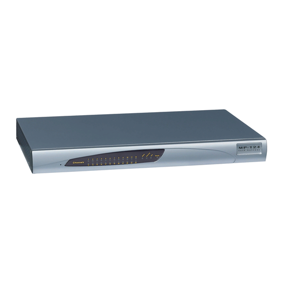
- Page 1 MediaPack™ Series MP-11x & MP-124 Analog VoIP Media Gateways User's Manual Version 6.6 January 2014 Document # LTRT-65422...
-
Page 3: Table Of Contents
User's Manual Contents Table of Contents Overview ......................19 MediaPack Models ....................20 SIP Overview ......................20 Getting Started with Initial Connectivity ..............23 Assigning the OAMP IP Address ..............25 Web Interface ......................25 BootP/TFTP Server ....................27 CLI .......................... 28 FXS Voice Menu Guidance .................. - Page 4 MP-11x & MP-124 Configuring Web and Telnet Access List ............... 70 Configuring RADIUS Settings ................72 CLI-Based Management ..................73 Enabling CLI using Telnet ..................73 Enabling CLI using SSH and RSA Public Key ............73 Establishing a CLI Session ..................75 CLI Commands ......................
- Page 5 User's Manual Contents 11.2 Configuring IP Network Interfaces ............... 105 11.2.1 Assigning NTP Services to Application Types ............110 11.2.2 Multiple Interface Table Configuration Rules............111 11.2.3 Troubleshooting the Multiple Interface Table ............112 11.2.4 Networking Configuration Examples ..............112 11.2.4.1 One VoIP Interface for All Applications ..........112 11.2.4.2 VoIP Interface per Application Type ............
- Page 6 MP-11x & MP-124 13.2.1.8 RFC 2833 ANS Report upon Fax/Modem Detection ......153 13.2.2 V.34 Fax Support ....................153 13.2.2.1 Bypass Mechanism for V.34 Fax Transmission ........153 13.2.2.2 Relay Mode for T.30 and V.34 Faxes ........... 154 13.2.3 V.152 Support ......................154 13.2.4 Fax Transmission behind NAT ................155 13.3 Configuring RTP/RTCP Settings ................
- Page 7 User's Manual Contents 21 Manipulation ....................209 21.1 Configuring General Settings ................209 21.2 Configuring Source/Destination Number Manipulation Rules ......209 21.3 Manipulating Number Prefix ................. 214 21.4 SIP Calling Name Manipulations ................215 21.5 Configuring Redirect Number IP to Tel ..............218 21.6 Mapping NPI/TON to SIP Phone-Context ............
- Page 8 MP-11x & MP-124 24.13 Configuring Voice Mail ..................260 25 Analog Gateway ....................261 25.1 Configuring Keypad Features ................261 25.2 Configuring Metering Tones ................. 262 25.3 Configuring Charge Codes ................... 263 25.4 Configuring FXO Settings ..................264 25.5 Configuring Authentication ................... 265 25.6 Configuring Automatic Dialing ................
- Page 9 User's Manual Contents 27 SAS Configuration ..................297 27.1 General SAS Configuration .................. 297 27.1.1 Enabling the SAS Application ................297 27.1.2 Configuring Common SAS Parameters ..............297 27.2 Configuring SAS Outbound Mode ................ 300 27.3 Configuring SAS Redundant Mode ..............300 27.4 Configuring Gateway Application with SAS ............
- Page 10 32.4.4 TFTP Configuration using DHCP Option 66 ............353 32.4.5 HTTP-based Automatic Updates ................354 32.4.6 Configuration using FTP or NFS ................354 32.4.7 Configuration using AudioCodes EMS ..............355 32.5 Loading Files Securely (Disabling TFTP) ............. 355 32.6 Remotely Triggering Auto Update using SIP NOTIFY ......... 356 33 Restoring Factory Defaults ................
- Page 11 38 Syslog and Debug Recordings ..............391 38.1 Syslog Message Format ..................391 38.1.1 Event Representation in Syslog Messages ............392 38.1.2 Identifying AudioCodes Syslog Messages using Facility Levels ......394 38.1.3 SNMP Alarms in Syslog Messages ...............394 38.2 Configuring Syslog Settings ................. 395 38.3 Configuring Debug Recording ................
- Page 12 MP-11x & MP-124 43.3.1 General Parameters ....................439 43.3.2 SIP Test Call Parameters ..................440 43.3.3 Syslog, CDR and Debug Parameters ..............441 43.3.4 Resource Allocation Indication Parameters............444 43.3.5 BootP Parameters ....................445 43.4 Security Parameters ..................... 446 43.4.1 General Parameters ....................446 43.4.2 HTTPS Parameters ....................447 43.4.3 SRTP Parameters ....................449 43.4.4 TLS Parameters .....................451 43.4.5 SSH Parameters ....................453...
- Page 13 User's Manual Contents 44 DSP Templates ....................579 45 Selected Technical Specifications ..............581 Version 6.6 MP-11x & MP-124...
- Page 14 MP-11x & MP-124 Reader's Notes User's Manual Document #: LTRT-65422...
-
Page 15: Weee Eu Directive
Customer Support Customer technical support and services are provided by AudioCodes or by an authorized AudioCodes Service Partner. For more information on how to buy technical support for AudioCodes products and for contact information, please visit our Web site at www.audiocodes.com/support. -
Page 16: Regulatory Information
MP-11x & MP-124 Regulatory Information The Regulatory Information can be viewed at http://www.audiocodes.com/downloads. Related Documentation Manual Name SIP CPE Release Notes MP-11x & MP-124 SIP Installation Manual MP-11x SIP Fast Track Guide MP-124 AC SIP Fast Track Guide MP-124 DC SIP Fast Track Guide... - Page 17 This device includes cryptographic software written by Eric Young (eay@cryptsoft.com). Documentation Feedback AudioCodes continually strives to produce high quality documentation. If you have any comments (suggestions or errors) regarding this document, please fill out the Documentation Feedback form on our Web site at http://www.audiocodes.com/downloads.
- Page 18 MP-11x & MP-124 Reader's Notes User's Manual Document #: LTRT-65422...
-
Page 19: Overview
User's Manual 1. Overview Overview The MediaPack series analog Voice-over-IP (VoIP) Session Initiation Protocol (SIP) media gateways (hereafter referred to as device) are cost-effective, cutting edge technology products. These stand-alone analog VoIP devices provide superior voice technology for connecting legacy telephones, fax machines and Private Branch Exchange (PBX) systems to IP-based telephony networks, as well as for integration with new IP-based PBX architectures. -
Page 20: Mediapack Models
4 + 4 MP-114 2 + 2 MP-112* * The MP-112 differs from the MP-114 and MP-118 in that its configuration excludes the RS-232 connector and Lifeline option. SIP Overview Session Initiation Protocol (SIP) is an application-layer control (signaling) protocol used on the gateway for creating, modifying, and terminating sessions with one or more participants. - Page 21 F1 INVITE - 10.8.201.108 to 10.8.201.161: INVITE sip:2000@10.8.201.161;user=phone SIP/2.0 Via: SIP/2.0/UDP 10.8.201.108;branch=z9hG4bKacsiJkDGd From: <sip:6000@10.8.201.108>;tag=1c5354 To: <sip:2000@10.8.201.161> Call-ID: 534366556655skKw-6000--2000@10.8.201.108 CSeq: 18153 INVITE Contact: <sip:8000@10.8.201.108;user=phone> User-Agent: Audiocodes-Sip-Gateway/MediaPack/v.6.60.010.006 Supported: 100rel,em Allow: REGISTER,OPTIONS,INVITE,ACK,CANCEL,BYE, NOTIFY,PRACK,REFER,INFO Content-Type: application/sdp Content-Length: 208 o=AudiocodesGW 18132 74003 IN IP4 10.8.201.108 s=Phone-Call c=IN IP4 10.8.201.108...
- Page 22 MP-11x & MP-124 Contact: <sip:2000@10.8.201.161;user=phone> Server: Audiocodes-Sip-Gateway/MediaPack/v.6.60.010.006 Supported: 100rel,em Allow: REGISTER,OPTIONS,INVITE,ACK,CANCEL,BYE, NOTIFY,PRACK,REFER,INFO Content-Type: application/sdp Content-Length: 206 o=AudiocodesGW 30221 87035 IN IP4 10.8.201.161 s=Phone-Call c=IN IP4 10.8.201.10 t=0 0 m=audio 7210 RTP/AVP 8 96 a=rtpmap:8 pcma/8000 a=ptime:20 a=rtpmap:96 telephone-event/8000 a=fmtp:96 0-15 ...
-
Page 23: Getting Started With Initial Connectivity
Part I Getting Started with Initial Connectivity... -
Page 25: Assigning The Oamp Ip Address
User's Manual 2. Assigning the OAMP IP Address Assigning the OAMP IP Address The device is shipped with a factory default IP address for its operations, administration, maintenance, and provisioning (OAMP) interface, as shown in the table below: Table 2-1: Default OAMP IP Address IP Address Value ... - Page 26 MP-11x & MP-124 Figure 2-2: MP-124 Ethernet Connection to PC for Initial Connectivity Change the IP address and subnet mask of your computer to correspond with the default IP address and subnet mask of the device. Access the Web interface: On your computer, start a Web browser and in the URL address field, enter the default IP address of the device;...
-
Page 27: Bootp/Tftp Server
BootP/TFTP Server You can assign an IP address to the device using BootP/TFTP protocols. This can be done using the AudioCodes AcBootP utility (supplied) or any standard compatible BootP server. Note: You can also use the AcBootP utility to load the software file (.cmp) and configuration file (.ini). -
Page 28: Cli
MP-11x & MP-124 • ‘Subnet’: Enter the new subnet mask (in dotted-decimal notation) that you want to assign the device. • ‘Gateway’: Enter the IP address of the Default Gateway (if required). Click Apply to save the new client. Physically reset the device by powering it down and then up again. This enables the device to receive its new networking parameters through the BootP process. -
Page 29: Fxs Voice Menu Guidance
User's Manual 2. Assigning the OAMP IP Address At the prompt, type the following command to access the configuration folder, and then press Enter: conf At the prompt, type the following command to view the current network settings, and then press Enter: GCP IP At the prompt, typing the following command to change the network settings, and then press Enter:... - Page 30 Configuration File Name Pattern Description http://aa.bb.cc.dd/config.ini Standard config.ini. https://aa.bb.cc.dd/config.ini Secure HTTP. The device's MAC address is appended to the file http://aa.bb.cc.dd/audiocodes/<MAC>.ini name (e.g., http://36.44.0.6/audiocodes/00908f012300.ini). http://aa.bb.cc.dd:8080/config.ini HTTP on port 8080. http://aa.bb.cc.dd:1400/config.ini HTTP on port 1400. Generating configuration per IP/MAC address http://aa.bb.cc.dd/cgi-...
- Page 31 User's Manual 2. Assigning the OAMP IP Address print "; Request for MAC=$mac IP=$ip\n\n"; print <<"EOF"; SyslogServerIP = 36.44.0.15 EnableSyslog = 1 SSHServerEnable = 1 The table below lists the configuration parameters that can be viewed and modified using the voice menu: Table 2-2: Voice Menu Configuration Parameters Item Number at Description...
- Page 32 MP-11x & MP-124 Reader's Notes User's Manual Document #: LTRT-65422...
-
Page 33: Management Tools
Part II Management Tools... -
Page 35: Introduction
Embedded HTTP/S-based Web server - see 'Web-based Management' on page Command Line Interface (CLI) - see 'CLI-Based Management' on page AudioCodes Element Management System - see EMS-Based Management on page Simple Network Management Protocol (SNMP) browser software - see 'SNMP-Based Management' on page ... - Page 36 MP-11x & MP-124 Reader's Notes User's Manual Document #: LTRT-65422...
-
Page 37: Web-Based Management
User's Manual 4. Web-Based Management Web-Based Management The device provides an embedded Web server (hereafter referred to as Web interface), supporting fault management, configuration, accounting, performance, and security (FCAPS), including the following: Full configuration Software and configuration upgrades ... -
Page 38: Accessing The Web Interface
MP-11x & MP-124 4.1.2 Accessing the Web Interface The procedure below describes how to access the Web interface. To access the Web interface: Open a standard Web browser (see 'Computer Requirements' on page 37). In the Web browser, specify the IP address of the device (e.g., http://10.1.10.10); the Web interface's Login window appears, as shown below: Figure 4-1: Web Login Screen In the 'Username' and 'Password' fields, enter the case-sensitive, user name and... -
Page 39: Areas Of The Gui
Figure 4-2: Main Areas of the Web Interface GUI Table 4-1: Description of the Web GUI Areas Item # Description Displays AudioCodes (corporate) logo image. Displays the product name. Toolbar, providing frequently required command buttons. For more information, see 'Toolbar Description' on page 40. -
Page 40: Toolbar Description
MP-11x & MP-124 4.1.4 Toolbar Description The toolbar provides frequently required command buttons, described in the table below: Table 4-2: Description of Toolbar Buttons Icon Button Description Name Submit Applies parameter settings to the device (see 'Saving Configuration' on page 324). Note: This icon is grayed out when not applicable to the currently opened page. -
Page 41: Navigation Tree
User's Manual 4. Web-Based Management 4.1.5 Navigation Tree The Navigation tree is located in the Navigation pane and displays a tree-like structure of menus pertaining to the selected tab on the Navigation bar. You can drill-down to the required page item level to open its corresponding page in the Work pane. The terminology used throughout this manual for referring to the hierarchical structure of the tree is as follows: ... -
Page 42: Showing / Hiding The Navigation Pane
MP-11x & MP-124 (i.e., Configuration, Maintenance, and Status & Diagnostics) on the Navigation bar. The advantage of the Basic view is that it prevents "cluttering" of the Navigation tree with menus that may not be required. To toggle between Full and Basic view: ... -
Page 43: Working With Configuration
User's Manual 4. Web-Based Management To show the Navigation pane: Click the right-pointing arrow ; the pane is displayed and the button is replaced by the left-pointing arrow button. Figure 4-6: Show and Hide Button (Navigation Pane in Hide View) 4.1.6 Working with Configuration Pages The configuration pages contain the parameters for configuring the device and are... -
Page 44: Viewing Parameters
MP-11x & MP-124 4.1.6.2 Viewing Parameters Some pages allow you to view a reduced or expanded display of parameters. The Web interface provides two methods for displaying page parameters: Displaying "basic" and "advanced" parameters - see 'Displaying Basic and Advanced Parameters' on page ... -
Page 45: Modifying And Saving Parameters
User's Manual 4. Web-Based Management 4.1.6.2.2 Showing / Hiding Parameter Groups Some pages provide groups of parameters, which can be hidden or shown. To toggle between hiding and showing a group, simply click the group title button that appears above each group. -
Page 46: Working With Tables
MP-11x & MP-124 Note: Parameters saved to the volatile memory (by clicking Submit), revert to their previous settings after a hardware or software reset, or if the device is powered down. Therefore, to ensure parameter changes (whether on-the-fly or not) are retained, save ('burn') them to the device's non-volatile memory, i.e., flash (see 'Saving Configuration' on page 324). - Page 47 User's Manual 4. Web-Based Management Item # Button / Field Index. Index radio button Selects the row for editing and deleting. Compact button Organizes the index entries in ascending, consecutive order, starting from index 0. For example, assume you have three index entries, 0, 4 and 6. After you click Compact, index entry 4 is re-assigned to index 1 and index entry 6 is re-assigned to index 2.
- Page 48 MP-11x & MP-124 Item # Button Toggles between displaying and hiding the full configuration of a Show/Hide selected row. This configuration is displayed below the table (see Item #6) and is useful for large tables that cannot display all its columns in the work pane.
-
Page 49: Searching For Configuration Parameters
User's Manual 4. Web-Based Management Item # Description default is 10. Displays the currently displayed page number. 4.1.7 Searching for Configuration Parameters You can locate the exact Web page on which a specific parameter appears, by using the device's Search feature. The Web parameter's corresponding ini file parameter name is used as the search key. -
Page 50: Working With Scenarios
MP-11x & MP-124 Table 4-6: Search Description Item # Description Search field for entering search key and Search button for activating the search process. Search results listed in Navigation pane. Found parameter, highlighted on relevant Web page 4.1.8 Working with Scenarios The Web interface allows you to create your own menu (Scenario) of up to 20 pages, selected from the menus in the Navigation tree (i.e., pertaining to the Configuration, Maintenance, and Status &... - Page 51 User's Manual 4. Web-Based Management Repeat steps 5 through 7 to add additional Steps (i.e., pages). When you have added all the required Steps for your Scenario, click the Save & Finish button located at the bottom of the Navigation tree; a message box appears informing you that the Scenario has been successfully created.
-
Page 52: Accessing A Scenario
MP-11x & MP-124 Notes: • You can add up to 20 Steps per Scenario, where each Step can contain up to 25 parameters. • When in Scenario mode, the Navigation tree is in 'Full' display (i.e., all menus are displayed in the Navigation tree) and the configuration pages are in 'Advanced Parameter List' display (i.e., all parameters are shown in the pages). -
Page 53: Editing A Scenario
User's Manual 4. Web-Based Management Item Description background. Navigation buttons for navigating between Scenario Steps: Next button to open the next Step listed in the Scenario Previous button to open the previous Step listed in the Scenario Note: If you reset the device while in Scenario mode, after the device resets, you are returned once again to the Scenario mode. -
Page 54: Saving A Scenario To A Pc
MP-11x & MP-124 • Edit Scenario Name: In the 'Scenario Name' field, edit the Scenario name. On the displayed page, click Next. • Remove a Step: In the Navigation tree, select the required Step; the corresponding page opens in the Work pane. On the page, clear all the check boxes corresponding to the parameters. -
Page 55: Loading A Scenario To The Device
ScenarioFileName (see Web and Telnet Parameters on page 431). The Scenario file must be located in the same folder as the ini file. For information on using AudioCodes AcBootP utility, refer to AcBootP Utility User's Guide. -
Page 56: Quitting Scenario Mode
MP-11x & MP-124 Click OK; the Scenario is deleted and the Scenario mode closes. Note: You can also delete a Scenario using the following alternative methods: • Loading an empty dat file (see 'Loading a Scenario to the Device' on page 55). -
Page 57: Creating A Login Welcome Message
User's Manual 4. Web-Based Management 4.1.9 Creating a Login Welcome Message You can create a Welcome message box that is displayed on the Web Login page for logging in to the Web interface. The figure below displays an example of a Welcome message: Figure 4-22: User-Defined Web Welcome Message after Login To enable and create a Welcome message, use the WelcomeMessage table ini file... -
Page 58: Getting Help
MP-11x & MP-124 4.1.10 Getting Help The Web interface provides you with context-sensitive Online Help. The Online Help provides brief descriptions of parameters pertaining to the currently opened page. To view the Help topic of a currently opened page: On the toolbar, click the Help button;... -
Page 59: Logging Off The Web Interface
On the toolbar, click the Home icon. Figure 4-25: MP-11x Home Page Figure 4-26: MP-124 Home Page Note: The displayed number and type (FXO and/or FXS) of channels depends on the ordered model (e.g., MP-118 or MP-114). Version 6.6 MP-11x & MP-124... - Page 60 MP-11x & MP-124 In addition to the color-coded status information depicted on the graphical display of the device, the Home page displays various read-only information in the General Information pane: IP Address: IP address of the device Subnet Mask: Subnet mask address of the device ...
-
Page 61: Assigning A Port Name
User's Manual 4. Web-Based Management 4.2.1 Assigning a Port Name The Home page allows you to assign an arbitrary name or a brief description to each port. This description appears as a tooltip when you move your mouse over the port. Note: Only alphanumerical characters can be used in the port description. -
Page 62: Configuring Web User Accounts
MP-11x & MP-124 Configuring Web User Accounts You can create up to 5 Web user accounts for the device. Up to five Web users can simultaneously be logged in to the device's Web interface. Web user accounts prevent unauthorized access to the Web interface, enabling login access only to users with correct credentials (i.e., username and password). -
Page 63: Basic User Accounts Configuration
User's Manual 4. Web-Based Management unsuccessful login attempts. Login information (such as how many login attempts were made and the last successful login time) can be presented to the user. To prevent user access after a specific number of failed logins: From the 'Deny Access On Fail Count' drop-down list, select the number of failed logins after which the user is prevented access to the device for a user-defined time (see next step). - Page 64 MP-11x & MP-124 To configure the two pre-configured Web user accounts: Open the Web User Accounts page (Configuration tab > System menu > Web User Accounts). If you are logged in as Security Administrator, both Web user accounts are displayed (as shown below). If you are logged in with the second user account, only the details of this user account are displayed.
-
Page 65: Advanced User Accounts Configuration
User's Manual 4. Web-Based Management 4.3.2 Advanced User Accounts Configuration This section describes advanced Web user account configuration. This is relevant if you need the following management scheme: Enhanced security settings per Web user (e.g., limit session duration) More than two Web user accounts (up to 5 Web user accounts) ... - Page 66 MP-11x & MP-124 The Web Users table appears, listing the two default, pre-configured Web use accounts - Security Administrator ("Admin") and Monitor ("User"): Figure 4-30: Web Users Table Page Click the Add button; the following dialog box is displayed: Figure 4-31: Web Users Table - Add Record Dialog Box Add a user as required.
- Page 67 User's Manual 4. Web-Based Management Parameter Description Web: Status Defines the status of the Web user. New = (Default) User is required to change its password on the next login. When the user logs in to the Web interface, the user is immediately prompted to change the current password.
-
Page 68: Displaying Login Information Upon Login
MP-11x & MP-124 Parameter Description Web: User Level Defines the user's access level. Monitor = (Default) Read-only user. This user can only view Web pages and access to security-related pages is denied. Admin = Read/write privileges for all pages, except security-related pages including the Web Users table where this user has only read- only privileges. -
Page 69: Configuring Web Security Settings
- what the user has (i.e., the physical card) and what the user knows (i.e., the login password). This feature is enabled using the EnableMgmtTwoFactorAuthentication parameter. Note: For specific integration requirements for implementing a third-party smart card for Web login authentication, contact your AudioCodes representative. Version 6.6 MP-11x & MP-124... -
Page 70: Configuring Web And Telnet Access List
MP-11x & MP-124 To log in to the Web interface using CAC: Insert the Common Access Card into the card reader. Access the device using the following URL: https://<host name or IP address>; the device prompts for a username and password. Enter the password only. - Page 71 User's Manual 4. Web-Based Management To delete authorized IP addresses, select the Delete Row check boxes corresponding to the IP addresses that you want to delete, and then click Delete Selected Addresses; the IP addresses are removed from the table and these IP addresses can no longer access the Web and Telnet interfaces.
-
Page 72: Configuring Radius Settings
MP-11x & MP-124 Configuring RADIUS Settings The RADIUS Settings page is used for configuring the Remote Authentication Dial In User Service (RADIUS) accounting parameters. For a description of these parameters, see 'Configuration Parameters Reference' on page 421. To configure RADIUS: Open the RADIUS Settings page (Configuration tab >... -
Page 73: Cli-Based Management
User's Manual 5. CLI-Based Management CLI-Based Management This section provides an overview of the CLI-based management and configuration relating to CLI management. The device's CLI-based management interface can be accessed using the RS-232 serial port or by using Secure SHell (SSH) or Telnet through the Ethernet interface. - Page 74 MP-11x & MP-124 PuTTY, which downloaded from http://www.chiark.greenend.org.uk/~sgtatham/putty/. By default, SSH uses the same username and password as the Telnet and Web server. SSH supports 1024/2048-bit RSA public keys, providing carrier-grade security. Follow the instructions below to configure the device with an administrator RSA key as a means of strong authentication.
-
Page 75: Establishing A Cli Session
User's Manual 5. CLI-Based Management For additional security, you can set the 'Require Public Key' to Enable. This ensures that SSH access is only possible by using the RSA key and not by using user name and password. Configure the other SSH parameters as required. For a description of these parameters, see SSH Parameters on page 453. -
Page 76: Cli Commands
MP-11x & MP-124 At the password prompt, type the password, and then press Enter: password: Admin After logging in, the current directory (root), available commands, available subdirectories, and a welcome message are displayed at the CLI prompt: login: Admin password: ready. - Page 77 User's Manual 5. CLI-Based Management Command Short Format Arguments Description SHow DSP sh dsp status | perf Displays status and version for each DSP device, along with overall performance statistics. SHow IP sh ip conf | perf | Displays IP interface status and configuration, route along with performance statistics.
-
Page 78: Ping Command
MP-11x & MP-124 IP Packets TX: 1171 IP Packets RX: 5273 IP Packets TX per second: 3 IP Packets RX per second: 12 Peak KByte/s TX in this interval: 18 Peak KByte/s RX in this interval: 4 Discarded packets: 186 DHCP requests sent: 0 IPSec Security Associations: 0 />/mg/perf reset... -
Page 79: Management Commands
User's Manual 5. CLI-Based Management Command Short Format Arguments Description ip-address to each packet. cos: Class-of-Service (as per 802.1p) to use. Example: />ping 10.31.2.10 Ping process started for address 10.31.2.10. Process ID - 27. Reply from 10.31.2.10: bytes=0 time<0ms Reply from 10.31.2.10: bytes=0 time<0ms Reply from 10.31.2.10: bytes=0 time<0ms Reply from 10.31.2.10: bytes=0 time<0ms... - Page 80 MP-11x & MP-124 Command Short Arguments Description Format ConfigFile /conf/cf view | get | set Retrieves the full ini file from the device and allows loading a new ini file directly in the CLI session. Note: The argument view displays the file, page by page.
-
Page 81: Snmp-Based Management
User's Manual 6. SNMP-Based Management SNMP-Based Management The device provides an embedded SNMP Agent to operate with a third-party SNMP Manager (e.g., element management system or EMS) for operation, administration, maintenance, and provisioning (OAMP) of the device. The SNMP Agent supports standard Management Information Base (MIBs) and proprietary MIBs, enabling a deeper probe into the interworking of the device. -
Page 82: Configuring Snmp Trap Destinations
MP-11x & MP-124 To delete a community string, select the Delete check box corresponding to the community string that you want to delete, and then click Submit. Table 6-1: SNMP Community String Parameters Description Parameter Description Read Only [SNMPReadOnlyCommunityString_x]: Up to five Community String read-only community strings (up to 19 characters each). -
Page 83: Configuring Snmp Trusted Managers
User's Manual 6. SNMP-Based Management Table 6-2: SNMP Trap Destinations Parameters Description Parameter Description Web: SNMP Manager Enables the SNMP Manager to receive traps and checks [SNMPManagerIsUsed_x] the validity of the configured destination (IP address and port number). [0] (check box cleared) = (Default) Disables SNMP Manager ... -
Page 84: Configuring Snmp V3 Users
MP-11x & MP-124 To configure SNMP Trusted Managers: Open the SNMP Trusted Managers page (Configuration tab > System menu > Management submenu > SNMP submenu > SNMP Trusted Managers). Figure 6-2: SNMP Trusted Managers Select the check box corresponding to the SNMP Trusted Manager that you want to enable and for whom you want to define an IP address. - Page 85 User's Manual 6. SNMP-Based Management Notes: • If you delete a user that is associated with a trap destination (in 'Configuring SNMP Trap Destinations' on page 82), the configured trap destination becomes disabled and the trap user reverts to default (i.e., SNMPv2).
- Page 86 MP-11x & MP-124 Reader's Notes User's Manual Document #: LTRT-65422...
-
Page 87: Ems-Based Management
User's Manual 7. EMS-Based Management EMS-Based Management AudioCodes Element Management System (EMS) is an advanced solution for standards- based management of gateways within VoP networks, covering all areas vital for the efficient operation, administration, management and provisioning (OAM&P) of AudioCodes' families of gateways. - Page 88 MP-11x & MP-124 Reader's Notes User's Manual Document #: LTRT-65422...
-
Page 89: Ini File-Based Management
User's Manual 8. INI File-Based Management INI File-Based Management The device can be configured using an ini file, which is a text-based file with an ini file extension name that can be created using any standard text-based editor such as Notepad. - Page 90 MP-11x & MP-124 configured. • The first word of the Format line must be "FORMAT", followed by the Index field name and then an equal "=" sign. After the equal sign, the names of the columns are listed. • Columns must be separated by a comma ",". •...
-
Page 91: General Ini File Formatting Rules
• Load Auxiliary Files - see 'Loading Auxiliary Files' on page AudioCodes AcBootP utility, which uses Bootstrap Protocol (BootP) and acts as a TFTP server. For information on using the AcBootP utility, refer to AcBootP Utility User's Guide. ... -
Page 92: Modifying An Ini File
The file may be loaded to the device using TFTP or HTTP. These protocols are not secure and are vulnerable to potential hackers. To overcome this security threat, the AudioCodes DConvert utility allows you to binary-encode (encrypt) the ini file before loading it to the device. -
Page 93: General System Settings
Part III General System Settings... -
Page 95: Configuring Certificates
User's Manual 9. Configuring Certificates Configuring Certificates The Certificates page allows you to configure X.509 certificates, which are used for secure management of the device, secure SIP transactions, and other security applications. Note: The device is shipped with an active TLS setup. Thus, configure certificates only if required. -
Page 96: Loading A Private Key
MP-11x & MP-124 Copy the text and send it to your security provider. The security provider, also known as Certification Authority or CA, signs this request and then sends you a server certificate for the device. Save the certificate to a file (e.g., cert.txt). Ensure that the file is a plain-text file containing the"‘BEGIN CERTIFICATE"... - Page 97 User's Manual 9. Configuring Certificates load them over a physically-secure connection such as a back-to-back Ethernet cable connected directly to the managing computer. To replace the device's private key: Your security administrator should provide you with a private key in either textual PEM (PKCS #7) or PFX (PKCS #12) format.
-
Page 98: Mutual Tls Authentication
MP-11x & MP-124 Mutual TLS Authentication By default, servers using TLS provide one-way authentication. The client is certain that the identity of the server is authentic. When an organizational PKI is used, two-way authentication may be desired - both client and server should be authenticated using X.509 certificates. -
Page 99: Self-Signed Certificates
User's Manual 9. Configuring Certificates Self-Signed Certificates The device is shipped with an operational, self-signed server certificate. The subject name for this default certificate is 'ACL_nnnnnnn', where nnnnnnn denotes the serial number of the device. However, this subject name may not be appropriate for production and can be changed while still using self-signed certificates. -
Page 100: Loading Certificate Chain For Trusted Root
MP-11x & MP-124 the OCSP server for revocation information whenever a peer certificate is received (IPSec, TLS client mode, or TLS server mode with mutual authentication). To configure OCSP: Open the General Security Settings page (Configuration tab > VoIP menu > Security >... -
Page 101: Date And Time
User's Manual 10. Date and Time Date and Time The date and time of the device can be configured manually or it can be obtained automatically from a Simple Network Time Protocol (SNTP) server. 10.1 Configuring Date and Time Manually The date and time of the device can be configured manually. - Page 102 MP-11x & MP-124 client. The client slowly robs bits from the clock counter to update the clock to the correct time. If the clock is running too slow, then in an effort to catch the clock up, bits are added to the counter, causing the clock to update quicker and catch up to the correct time.
-
Page 103: General Voip Configuration
Part IV General VoIP Configuration... -
Page 105: Network
User's Manual 11. Network Network This section describes the network-related configuration. 11.1 Ethernet Interface Configuration The device's Ethernet connection can be configured, using the ini file parameter EthernetPhyConfiguration, to one of the following modes: Manual: • 10Base-T Full-Duplex • 100Base-TX Half-Duplex or 100Base-TX Full-Duplex ... - Page 106 MP-11x & MP-124 administration and security. This can be achieved by employing Layer-2 VLANs and Layer- 3 subnets. The figure below illustrates a typical network architecture where the device is configured with three network interfaces for the OAMP, call control, and media applications. The device is connected to a VLAN-aware switch for directing traffic from and to the device to the three separated Layer-3 broadcast domains according to VLAN tags (middle pane).
- Page 107 User's Manual 11. Network Notes: • Before adding IP network interfaces to the Multiple Interface table, see Multiple Interface Table Configuration Rules on page for the rules on configuring valid IP network interfaces. • When booting using BootP/DHCP protocols, an IP address is obtained from the server.
- Page 108 MP-11x & MP-124 Interface Settings group; a confirmation message box appears: Figure 11-3: Confirmation Message for Accessing the Multiple Interface Table Click OK; the Multiple Interface Table page appears: In the 'Add Index' field, enter the desired index number for the new interface, and then click Add Index;...
- Page 109 User's Manual 11. Network Parameter Description Configuration Rules on page 111. Web/EMS: IP Address Defines the IPv4 IP address in dotted-decimal notation. [InterfaceTable_IPAddress] Note: For valid configuration, see Multiple Interface Table Configuration Rules on page 111. Web/EMS: Prefix Length Defines the prefix length of the related IP address. This is a [InterfaceTable_PrefixLength] Classless Inter-Domain Routing (CIDR)-style representation of a dotted-decimal subnet notation.
-
Page 110: Assigning Ntp Services To Application Types
MP-11x & MP-124 Parameter Description Web/EMS: Primary DNS Server IP (Optional) Defines the primary DNS server's IP address (in address dotted-decimal notation), which is used for translating [InterfaceTable_PrimaryDNSServerI domain names into IP addresses for the interface. PAddress] By default, no IP address is defined. Web/EMS: Secondary DNS Server IP (Optional) Defines the secondary DNS server's IP address address... -
Page 111: Multiple Interface Table Configuration Rules
User's Manual 11. Network 11.2.2 Multiple Interface Table Configuration Rules The Multiple Interface table configuration must adhere to the following rules: Each interface must have its own subnet. Configuring two interfaces with addresses in the same subnet (e.g., 192.168.0.1/16 and 192.168.100.1/16) is invalid. ... -
Page 112: Troubleshooting The Multiple Interface Table
MP-11x & MP-124 Notes: • When configuring the network interfaces and VLANs in the Multiple Interface table using the Web interface, it is recommended to check that your configuration is valid, by clicking the Done button in the Multiple Interface Table page. •... -
Page 113: Voip Interface Per Application Type
User's Manual 11. Network VLANS are not required and the Native VLAN ID is irrelevant. Class of Service parameters may have default values. IP Routing table: Two routes are configured for directing traffic for subnet 201.201.0.0/16 to 192.168.0.2, and all traffic for subnet 202.202.0.0/16 to 192.168.0.3: Table 11-3: Example of IP Routing Table Destination IP Prefix Length... -
Page 114: Voip Interfaces For Combined Application Types
MP-11x & MP-124 11.2.4.3 VoIP Interfaces for Combined Application Types This example describes the configuration of multiple interfaces for the following applications: One interface for the OAMP application. Interfaces for Call Control and Media applications. Multiple Interface table: Table 11-6: Example of VoIP Interfaces of Combined Application Types in Multiple Interface Table Application... -
Page 115: Configuring The Ip Routing Table
User's Manual 11. Network A separate IP routing table enables you to configure static routing rules. Configuring the following static routing rules enables OAMP applications to access peers on subnet 17.17.0.0 through the gateway 192.168.0.1. Table 11-9: Separate Routing Table Example Destination IP Gateway IP Interface... - Page 116 MP-11x & MP-124 Notes: • You can delete only inactive routing rules. • The IP Routing table can also be configured using the table ini file parameter, StaticRouteTable. Table 11-10: IP Routing Table Description Parameter Description Destination IP Address Defines the IP address of the destination host/network. The [StaticRouteTable_Destination] destination can be a single host or a whole subnet, depending on the Prefix Length configured for this routing rule.
-
Page 117: Interface Column
User's Manual 11. Network 11.3.1 Interface Column This example describes the configuration of static IP routing rules. Configure network interfaces in the Multiple Interface table, as shown below: Table 11-11: Configured Network Interfaces in Multiple Interface Table Application Prefix VLAN Index IP Address Gateway... -
Page 118: Configuring Quality Of Service
MP-11x & MP-124 configure a routing rule, the device sends a notification message to the Syslog server reporting the problem. Common routing rule configuration errors may include the following: The IP address specified in the 'Gateway IP Address' field is unreachable from the interface specified in the 'Interface Name' field. - Page 119 User's Manual 11. Network Application Traffic / Network Types Class-of-Service (Priority) T.38 traffic Media Premium media Control Premium control SIP over TLS (SIPS) Control Premium control Management Bronze Syslog ICMP Management Determined by the initiator of the request Determined by the initiator of the Network ARP listener request...
-
Page 120: Disabling Icmp Redirect Messages
MP-11x & MP-124 11.5 Disabling ICMP Redirect Messages You can configure the device's handling of ICMP Redirect messages. These messages can either be rejected (ignored) or permitted. Note: You can also configure this feature using the ini file parameter DisableICMPRedirects (see 'Routing Parameters' on page 423). ... - Page 121 User's Manual 11. Network To configure the internal DNS table: Open the Internal DNS Table page (Configuration tab > VoIP menu > Network submenu > DNS submenu > Internal DNS Table). Click Add; the following dialog box appears: Figure 11-6: Internal DNS Table - Add Record Dialog Box Configure the DNS rule, as required.
-
Page 122: Configuring The Internal Srv Table
MP-11x & MP-124 11.6.2 Configuring the Internal SRV Table The Internal SRV Table page resolves host names to DNS A-Records. Three different A- Records can be assigned to each host name, where each A-Record contains the host name, priority, weight, and port. Notes: •... -
Page 123: Configuring Nfs Settings
User's Manual 11. Network Table 11-15: Internal SRV Table Parameter Description Parameter Description Domain Name Defines the host name to be translated. [Srv2Ip_InternalDomain] The valid value is a string of up to 31 characters. Transport Type Defines the transport type. [Srv2Ip_TransportType] ... -
Page 124: Network Address Translation Support
MP-11x & MP-124 Configure the NFS parameters according to the table below. Click the Submit button; the remote NFS file system is immediately applied, which can be verified by the appearance of the 'NFS mount was successful' message in the Syslog server. -
Page 125: Device Located Behind Nat
User's Manual 11. Network the number of global IP addresses required in a private network (global IP addresses are only used to connect to the Internet) and (2) better network security by hiding the internal architecture. The design of SIP creates a problem for VoIP traffic to pass through NAT. SIP uses IP addresses and port numbers in its message body. -
Page 126: Configuring A Static Nat Ip Address For All Interfaces
MP-11x & MP-124 STUN is used for signaling and the media streams. STUN works with many existing NAT types and does not require any special behavior. STUN enables the device to discover the presence (and types) of NATs and firewalls located between it and the public Internet. -
Page 127: Remote Ua Behind Nat
User's Manual 11. Network IP address for media of all outgoing SIP messages sent on any of its network interfaces to this public IP address. Note: The NAT IP address can also be configured using the ini file parameter, StaticNATIP. ... -
Page 128: No-Op Packets
11.9 Robust Receipt of Media Streams The “robust-media” mechanism is an AudioCodes proprietary mechanism to filter out unwanted media (i.e., RTP, RTCP, and T.38) streams that are sent to the same port number on the device. In practice, the media RTP/RTCP ports may receive additional multiple unwanted media streams as result of traces of previous calls, call control errors, or deliberate attacks. -
Page 129: Multiple Routers Support
User's Manual 11. Network 11.10 Multiple Routers Support Multiple routers support is designed to assist the device when it operates in a multiple routers network. The device learns the network topology by responding to Internet Control Message Protocol (ICMP) redirections and caches them as routing rules (with expiration time). - Page 130 MP-11x & MP-124 Reader's Notes User's Manual Document #: LTRT-65422...
-
Page 131: Security
User's Manual 12. Security Security This section describes the VoIP security-related configuration. 12.1 Configuring Firewall Settings The device provides an internal firewall that enables you to configure network traffic filtering rules (access list). You can add up to 50 firewall rules. The access list offers the following firewall possibilities: ... - Page 132 MP-11x & MP-124 To add firewall rules: Open the Firewall Settings page (Configuration tab > VoIP menu > Security submenu > Firewall Settings). Click the Add button; the following dialog box appears: Figure 12-1: Firewall Settings Page - Add Record Configure the firewall parameters, as required.
- Page 133 User's Manual 12. Security Value per Rule Parameter Burst Bytes 50000 50000 Action Upon Match Allow Allow Allow Allow Block The firewall rules in the above configuration example do the following: Rules 1 and 2: Typical firewall rules that allow packets ONLY from specified IP addresses (e.g., proxy servers).
- Page 134 MP-11x & MP-124 Parameter Description End Port Defines the destination UDP/TCP end port (on this device) to where [AccessList_End_Port] packets are sent. The valid range is 0 to 65535. Note: When the protocol type isn't TCP or UDP, the entire range must be provided.
-
Page 135: Configuring 802.1X Settings
User's Manual 12. Security Parameter Description Match Count (Read-only) Displays the number of packets accepted or rejected by [AccessList_MatchCount] the rule. 12.2 Configuring 802.1x Settings The 802.1x Settings page is used to configure IEEE 802.1X Ethernet security. The device can function as an IEEE 802.1X supplicant. IEEE 802.1X is a standard for port-level security on secure Ethernet switches;... -
Page 136: Configuring General Security Settings
MP-11x & MP-124 12.3 Configuring General Security Settings The General Security Settings page is used to configure various security features. For a description of the parameters appearing on this page, refer 'Configuration Parameters Reference' on page 421. To configure the general security parameters: Open the General Security Settings page (Configuration tab >... -
Page 137: Enabling Ipsec
User's Manual 12. Security • Key exchange (DH): The DH protocol creates the master key. DH requires both peers to agree on certain mathematical parameters, known as the "group". • Authentication: The two peers authenticate one another using a pre-shared key configured in the IP Security Associations Table or by using certificate-based authentication. - Page 138 MP-11x & MP-124 Note: You can also configure the IP Security Proposals table using the table ini file parameter IPsecProposalTable (see 'Security Parameters' on page 446). To configure IP Security Proposals: Open the IP Security Proposal Table page (Configuration tab > VoIP menu > Security submenu >...
-
Page 139: Configuring Ip Security Associations Table
User's Manual 12. Security If no proposals are defined, the default settings (shown in the following table) are applied. Table 12-4: Default IPSec/IKE Proposals Proposal Encryption Authentication DH Group Proposal 0 3DES SHA1 Group 2 (1024 bit) Proposal 1 3DES Group 2 (1024 bit) Proposal 2 3DES... - Page 140 MP-11x & MP-124 To configure the IPSec Association table: Open the IP Security Associations Table page (Configuration tab > VoIP menu > Security submenu > IPSec Association Table). Click the Add button; the following dialog box appears: Figure 12-5: IP Security Associations Table Page - Add Record Dialog Box Configure the parameters, as required.
- Page 141 User's Manual 12. Security Parameter Name Description Certificate' on page 95. Shared Key Defines the pre-shared key (in textual format). Both peers [IPsecSATable_SharedKey] must use the same pre-shared key for the authentication process to succeed. Notes: This parameter is applicable only if the Authentication Method parameter is set to pre-shared key.
- Page 142 MP-11x & MP-124 Parameter Name Description [1] DPD Periodic = DPD is enabled with message exchanges at regular intervals [2] DPD on demand = DPD is enabled with on-demand checks - message exchanges as needed (i.e., before sending data to the peer). If the liveliness of the peer is questionable, the device sends a DPD message to query the status of the peer.
-
Page 143: Media
User's Manual 13. Media Media This section describes the media-related configuration. 13.1 Configuring Voice Settings The Voice Settings page configures various voice parameters such as voice volume, silence suppression, and DTMF transport type. For a detailed description of these parameters, see 'Configuration Parameters Reference' on page 421. ... -
Page 144: Silence Suppression (Compression)
MP-11x & MP-124 Configure the following parameters: • 'Voice Volume' (VoiceVolume) - Defines the voice gain control (in decibels) for IP- to-Tel • 'Input Gain' (InputGain) - Defines the PCM input gain control (in decibels) for Tel- to-IP Click Submit to apply your settings. 13.1.2 Silence Suppression (Compression) Silence suppression (compression) is a method for conserving bandwidth on VoIP calls by not sending packets when silence is detected. - Page 145 User's Manual 13. Media The procedure below describes how to configure echo cancellation using the Web interface: To configure echo cancellation using the Web interface: Open the Voice Settings page (Configuration tab > VoIP menu > Media submenu > Voice Settings).
-
Page 146: Fax And Modem Capabilities
MP-11x & MP-124 13.2 Fax and Modem Capabilities This section describes the device's fax and modem capabilities and corresponding configuration. The fax and modem configuration is done in the Fax/Modem/CID Settings page. Notes: • Unless otherwise specified, the configuration parameters mentioned in this section are available on this page. -
Page 147: Fax/Modem Transport Modes
User's Manual 13. Media 13.2.1 Fax/Modem Transport Modes The device supports the following transport modes for fax per modem type (V.22/V.23/Bell/V.32/V.34): T.38 fax relay (see 'T.38 Fax Relay Mode' on page 147) G.711 Transport: switching to G.711 when fax/modem is detected (see 'G.711 Fax / Modem Transport Mode' on page 148) ... -
Page 148: Fax / Modem Transport Mode
MP-11x & MP-124 To configure T.38 mode using SIP Re-INVITE messages: In the SIP General Parameters page (Configuration tab > VoIP menu > SIP Definitions > General Parameters), set the 'Fax Signaling Method' parameter to T.38 Relay (IsFaxUsed = 1). In the Fax/Modem/CID Settings page, configure the following optional parameters: •... -
Page 149: Fax Fallback
User's Manual 13. Media After a few seconds upon detection of fax V.21 preamble or super G3 fax signals, the device sends a second Re-INVITE enabling the echo canceller (the echo canceller is disabled only on modem transmission). A ‘gpmd’ attribute is added to the SDP according to the following format: ... - Page 150 MP-11x & MP-124 Enables echo cancellation for fax Disables echo cancellation for modem Performs certain jitter buffering optimizations The network packets generated and received during the bypass period are regular voice RTP packets (per the selected bypass coder), but with a different RTP payload type according to the following parameters: ...
-
Page 151: Fax / Modem Nse Mode
INVITE messages are sent. The voice channel is optimized for fax/modem transmission (same as for usual bypass mode). The parameters defining payload type for AudioCodes proprietary Bypass mode -- 'Fax Bypass Payload Type' (RTP/RTCP Settings page) and ModemBypassPayloadType (ini file) -- are not used with NSE Bypass. -
Page 152: Fax / Modem Transparent With Events Mode
MP-11x & MP-124 13.2.1.6 Fax / Modem Transparent with Events Mode In this mode, fax and modem signals are transferred using the current voice coder with the following automatic adaptations: Echo Canceller = on (or off for modems) Echo Canceller Non-Linear Processor Mode = off ... -
Page 153: Rfc 2833 Ans Report Upon Fax/Modem Detection
User's Manual 13. Media Configure the following optional parameters: Coders table - (Configuration tab > VoIP menu > Coders and Profiles > Coders). 'Dynamic Jitter Buffer Optimization Factor' (DJBufOptFactor) - RTP/RTCP Settings page (Configuration tab > VoIP menu > Media > RTP/RTCP Settings). 'Silence Suppression' (EnableSilenceCompression) - Voice Settings page (Configuration tab >... -
Page 154: Relay Mode For T.30 And V.34 Faxes
MP-11x & MP-124 To use bypass mode for T.30 and V.34 faxes: In the Fax/Modem/CID Settings page, do the following: Set the 'Fax Transport Mode' parameter to Bypass (FaxTransportMode = 2). Set the 'V.22 Modem Transport Type' parameter to Enable Bypass (V22ModemTransportType = 2). -
Page 155: Fax Transmission Behind Nat
User's Manual 13. Media VBD is supported and associated RTP payload types ('gpmd' SDP attribute), supported codecs, and packetization periods for all codec payload types ('ptime' SDP attribute). After this initial negotiation, no Re-INVITE messages are necessary as both endpoints are synchronized in terms of the other side's capabilities. -
Page 156: Configuring Rtp/Rtcp Settings
MP-11x & MP-124 13.3 Configuring RTP/RTCP Settings This section describes configuration relating to Real-Time Transport Protocol (RTP) and RTP Control Protocol (RTCP). 13.3.1 Configuring the Dynamic Jitter Buffer Voice frames are transmitted at a fixed rate. If the frames arrive at the other end at the same rate, voice quality is perceived as good. -
Page 157: Comfort Noise Generation
User's Manual 13. Media To configure jitter buffer using the Web interface: Open the RTP/RTCP Settings page (Configuration tab > VoIP menu > Media submenu > RTP/RTCP Settings). The relevant parameters are listed under the 'General Settings' group, as shown below: Figure 13-5: Jitter Buffer Parameters in the RTP/RTCP Settings Page Set the 'Dynamic Jitter Buffer Minimum Delay' parameter (DJBufMinDelay) to the minimum delay (in msec) for the Dynamic Jitter Buffer. - Page 158 MP-11x & MP-124 remote side in INFO messages. To enable this mode, define the following: Set the 'Declare RFC 2833 in SDP' parameter to No (RxDTMFOption = 0). Set the '1st Tx DTMF Option' parameter to INFO (Nortel) (TxDTMFOption = 1). Note: In this mode, DTMF digits are removed from the audio stream (and the 'DTMF Transport Type' parameter is automatically set to Mute DTMF).
-
Page 159: Configuring Rfc 2833 Payload
User's Manual 13. Media The following parameters affect the way the device handles the DTMF digits: TxDTMFOption, RxDTMFOption, RFC2833TxPayloadType, and RFC2833RxPayloadType MGCPDTMFDetectionPoint, DTMFVolume, DTMFTransportType, DTMFDigitLength, and DTMFInterDigitInterval 13.3.3.2 Configuring RFC 2833 Payload The procedure below describes how to configure the RFC 2833 payload using the Web interface: ... -
Page 160: Configuring Analog Settings
BaseUDPPort is set to 6,000, then the UDP port range is 6,000 to 6,030 MP-118: BaseUDPport to (BaseUDPport + 7*10) - for example, if the BaseUDPPort is set to 6,000, then the UDP port range is 6,000 to 6,070 ... -
Page 161: Configuring Dsp Templates
User's Manual 13. Media To configure the analog parameters: Open the Analog Settings page (Configuration tab > VoIP menu > Media submenu > Analog Settings). Figure 13-9: Analog Settings Page Configure the parameters as required. Click Submit to apply your changes. To save the changes to flash memory, see 'Saving Configuration' on page 324. -
Page 162: Configuring Media Security
MP-11x & MP-124 13.6 Configuring Media Security The device supports Secured RTP (SRTP) according to RFC 3711. SRTP is used to encrypt RTP and RTCP transport for protecting VoIP traffic. SRTP requires a key exchange mechanism that is performed according to RFC 4568 – “Session Description Protocol (SDP) Security Descriptions for Media Streams”. - Page 163 User's Manual 13. Media To configure media security: Open the Media Security page (Configuration tab > VoIP menu > Media submenu > Media Security). Configure the parameters as required. Click Submit to apply your changes. To save the changes to flash memory, see 'Saving Configuration' on page 324. Version 6.6 MP-11x &...
- Page 164 MP-11x & MP-124 Reader's Notes User's Manual Document #: LTRT-65422...
-
Page 165: Services
User's Manual 14. Services Services This section describes configuration for various supported services. 14.1 Least Cost Routing This section provides a description of the device's least cost routing (LCR) feature and how to configure it. 14.1.1 Overview The LCR feature enables the device to choose the outbound IP destination routing rule based on lowest call cost. - Page 166 MP-11x & MP-124 If four matching routing rules are located in the routing table and each one is assigned a different Cost Group as listed in the table above, then the rule assigned Cost Group "D" is selected. Note that for one minute, Cost Groups "A" and "D" are identical, but due to the average call duration, Cost Group "D"...
-
Page 167: Configuring Lcr
User's Manual 14. Services Example 3: This example shows how the cost of a call is calculated if the call spans over multiple time bands: Assume a Cost Group, "CG Local" is configured with two time bands, as shown below: Connection Cost Group Time Band... - Page 168 MP-11x & MP-124 To enable LCR: Open the Routing Rule Groups Table page (Configuration tab > VoIP menu > Services submenu > Least Cost Routing > Routing Rule Groups Table). Click the Add button; the Add Record dialog box appears: Figure 14-2: Routing Rule Groups Table - Add Record Configure the parameters as required.
-
Page 169: Configuring Cost Groups
User's Manual 14. Services Parameter Description Default Cost Determines whether routing rules in the Outbound IP Routing [RoutingRuleGroups_LCRDefa table without an assigned Cost Group are considered a higher ultCost] cost or lower cost route compared to other matched routing rules that are assigned Cost Groups. -
Page 170: Configuring Time Bands For Cost Groups
MP-11x & MP-124 Parameter Description Cost Group Name Defines an arbitrary name for the Cost Group. [CostGroupTable_CostGroupNam The valid value is a string of up to 30 characters. Note: Each Cost Group must have a unique name. Default Connect Cost Defines the call connection cost (added as a fixed charge to [CostGroupTable_DefaultConnecti the call) for a call outside the time bands. - Page 171 User's Manual 14. Services Configure the parameters as required. For a description of the parameters, see the table below. Click Submit; the entry is added to the Time Band table for the relevant Cost Group. Table 14-4: Time Band Table Description Parameter Description Index...
-
Page 172: Assigning Cost Groups To Routing Rules
MP-11x & MP-124 14.1.2.4 Assigning Cost Groups to Routing Rules Once you have configured your Cost Groups, you need to assign them to routing rules in the Outbound IP Routing table - see Configuring Tel to IP Routing on page 223. -
Page 173: Enabling Applications
User's Manual 15. Enabling Applications Enabling Applications In addition to the Gateway application (i.e., IP-to-Tel and Tel-to-IP calling), the device supports the following main application: Stand-Alone Survivability (SAS) application The procedure below describes how to enable these applications. Once an application is enabled, the Web GUI provides menus and parameter fields relevant to the application. - Page 174 MP-11x & MP-124 Reader's Notes User's Manual Document #: LTRT-65422...
-
Page 175: Control Network
User's Manual 16. Control Network Control Network This section describes configuration of the network at the SIP control level. 16.1 Configuring IP Groups The IP Group Table page allows you to create up to nine logical IP entities called IP Groups. - Page 176 MP-11x & MP-124 To configure IP Groups: Open the IP Group Table page (Configuration tab > VoIP menu > Control Network submenu > IP Group Table). Click the Add button: the following dialog box appears: Configure the IP Group parameters according to the table below. Click Submit.
- Page 177 User's Manual 16. Control Network Parameter Description forwarded by the device to another IP Group. Note: This parameter is overridden by the ‘Contact User’ parameter in the ‘Account’ table (see 'Configuring Account Table' on page 183). Local Host Name Defines the host name (string) that the device uses in the SIP message's Via and Contact headers.
-
Page 178: Configuring Proxy Sets Table
MP-11x & MP-124 Parameter Description the Proxy. If routing to the Proxy also fails, the Redirect / Transfer request is rejected. When this parameter is set to [2], the XferPrefix parameter can be used to define different routing rules for redirected calls. - Page 179 User's Manual 16. Control Network To configure Proxy Sets: Open the Proxy Sets Table page (Configuration tab > VoIP menu > Control Network submenu > Proxy Sets Table). Figure 16-1: Proxy Sets Table Page From the 'Proxy Set ID' drop-down list, select an ID for the desired group. Configure the Proxy parameters, as required.
- Page 180 MP-11x & MP-124 Parameter Description Group Settings table. According to the Tel to IP Routing if the parameter PreferRouteTable is set to 1. To the default Proxy. Typically, when IP Groups are used, there is no need to use the default Proxy and all routing and registration rules can be configured using IP Groups and the Account tables (see 'Configuring Account Table' on page 183).
- Page 181 User's Manual 16. Control Network Parameter Description defined interval (configured by the parameter ProxyKeepAliveTime). If set to 'Using Register', the SIP REGISTER message is sent every user- defined interval (configured by the RegistrationTime parameter). Any response from the Proxy, either success (200 OK) or failure (4xx response) is considered as if the Proxy is communicating correctly.
- Page 182 MP-11x & MP-124 Parameter Description value. Web/EMS: Is Proxy Hot- Enables the Proxy Hot-Swap redundancy mode. Swap [0] No (default) [ProxySet_IsProxyHotS [1] Yes wap] If Proxy Hot-Swap is enabled, the SIP INVITE/REGISTER message is initially sent to the first Proxy/Registrar server. If there is no response from the first Proxy/Registrar server after a specific number of retransmissions (configured by the parameter HotSwapRtx), the message is resent to the next redundant Proxy/Registrar server.
-
Page 183: Sip Definitions
User's Manual 17. SIP Definitions SIP Definitions This section describes configuration of SIP parameters. 17.1 Configuring SIP Parameters Many of the stand-alone SIP parameters associated with various features can be configured in the following pages: SIP General Parameters page: Provides SIP parameters for configuring general SIP features. - Page 184 MP-11x & MP-124 Configure the Account parameters according to the table below. Click the Apply button to save your changes. To save the changes, see 'Saving Configuration' on page 324. To perform registration, click the Register button; to unregister, click Unregister. The registration method for each Trunk Group is according to the setting of the 'Registration Mode' parameter in the Trunk Group Settings page.
- Page 185 User's Manual 17. SIP Definitions Parameter Description 'SIP Group Name' parameter configured in the IP Group table is used instead. Register Enables registration. [Account_Register] [0] No (Default) [1] Yes When enabled, the device sends REGISTER requests to the Serving IP Group.
-
Page 186: Configuring Proxy And Registration Parameters
MP-11x & MP-124 17.3 Configuring Proxy and Registration Parameters The Proxy & Registration page allows you to configure the Proxy server and registration parameters. For a description of the parameters appearing on this page, see 'Configuration Parameters Reference' on page 421. Note: To view the registration status of endpoints with a SIP Registrar/Proxy server, see Viewing Endpoint Registration Status on page 369. -
Page 187: Sip Message Authentication Example
REGISTER request is created. Since the algorithm is MD5: • The username is equal to the endpoint phone number "122". • The realm return by the proxy is "audiocodes.com". • The password from the ini file is "AudioCodes". Version 6.6 MP-11x & MP-124... - Page 188 MP-11x & MP-124 • The equation to be evaluated is "122:audiocodes.com:AudioCodes". According to the RFC, this part is called A1. • The MD5 algorithm is run on this equation and stored for future usage. • The result is "a8f17d4b41ab8dab6c95d3c14e34a9e1". The par called A2 needs to be evaluated: •...
-
Page 189: Coders And Profiles
User's Manual 18. Coders and Profiles Coders and Profiles This section describes configuration of the coders and SIP profiles parameters. 18.1 Configuring Coders The Coders page allows you to configure up to 10 voice coders for the device. Each coder can be configured with packetization time (ptime), bit rate, payload type, and silence suppression. - Page 190 MP-11x & MP-124 To configure the device's coders: Open the Coders page (Configuration tab > VoIP menu > Coders and Profiles submenu > Coders). Figure 18-1: Coders Table Page From the 'Coder Name' drop-down list, select the required coder. From the 'Packetization Time' drop-down list, select the packetization time (in msec) for the selected coder.
-
Page 191: Configuring Coder Groups
User's Manual 18. Coders and Profiles Coder Name Packetization Time Rate (kbps) Payload Silence (msec) Type Suppression [0] 5.3 [0] Disable G.723.1 30 (default), 60, 90, 120, (default) [g7231] [1] Enable [1] 6.3 [0] 16 [0] Disable G.726 10, 20 (default), 30, 40,... -
Page 192: Configuring Tel Profile
MP-11x & MP-124 To configure Coder Groups: Open the Coder Group Settings page (Configuration tab > VoIP menu > Coders and Profiles submenu > Coders Group Settings). Figure 18-2: Coder Group Settings Page From the 'Coder Group ID' drop-down list, select a Coder Group ID. From the 'Coder Name' drop-down list, select the first coder for the Coder Group. - Page 193 User's Manual 18. Coders and Profiles Note: Tel Profiles can also be configured using the table ini file parameter, TelProfile (see 'Configuration Parameters Reference' on page 421) To configure Tel Profiles: Open the Tel Profile Settings page (Configuration tab > VoIP menu > Coders and Profiles submenu >...
-
Page 194: Configuring Ip Profiles
MP-11x & MP-124 Note: If the coder lists of both IP and Tel Profiles apply to the same call, only the coders common to both are used. The order of the coders is determined by the preference. Configure the parameters as required. For a description of each parameter, refer to the corresponding "global"... - Page 195 User's Manual 18. Coders and Profiles To configure IP Profiles: Open the IP Profile Settings page (Configuration tab > VoIP menu > Coders and Profiles submenu > IP Profile Settings). From the 'Profile ID' drop-down list, select the IP Profile index. In the 'Profile Name' field, enter an arbitrary name that allows you to easily identify the IP Profile.
- Page 196 MP-11x & MP-124 Table 18-2: IP Profile Parameters Description Parameter Description Web: Profile ID Defines a unique index number for the IP Profile. [IpProfile_Index] Web: Profile Name (Optional) Defines a descriptive name for the IP Profile. [IpProfile_ProfileName] Common Parameters Web: RTP IP DiffServ For a description, see the global parameter [IpProfile_IPDiffServ] PremiumServiceClassMediaDiffServ.
- Page 197 User's Manual 18. Coders and Profiles Parameter Description Web: Copy Destination Number to For a description, see the global parameter Redirect Number CopyDest2RedirectNumber. [IpProfile_CopyDest2RedirectN umber] Web: Media Security Behavior For a description, see the global parameter MediaSecurityBehaviour. [IpProfile_MediaSecurityBehavi our] Web: CNG Detector Mode For a description, see the global parameter CNGDetectorMode.
- Page 198 MP-11x & MP-124 Parameter Description Web: Second Tx DTMF Option For a description, see the global parameter TxDTMFOption. [IpProfile_SecondTxDtmfOption Web: Declare RFC 2833 in SDP For a description, see the global parameter RxDTMFOption. [IpProfile_RxDTMFOption] Web: Enable Hold For a description, see the global parameter EnableHold. [IpProfile_EnableHold] User's Manual Document #: LTRT-65422...
-
Page 199: Gateway Application
Part V Gateway Application... -
Page 201: Introduction
User's Manual 19. Introduction Introduction This section describes configuration of the Gateway applications. The Gateway application refers to IP-to-Tel call routing and vice versa. Notes: • In some areas of the Web interface, the term "GW" application refers to the Gateway applications, respectively. •... - Page 202 MP-11x & MP-124 Reader's Notes User's Manual Document #: LTRT-65422...
-
Page 203: Hunt Group
User's Manual 20. Hunt Group Hunt Group This section describes the configuration of the device's channels, which entails assigning them to Hunt Groups. 20.1 Configuring Endpoint Phone Numbers The Endpoint Phone Number Table page allows you to activate the device's ports (channels or endpoints), by defining telephone numbers for the endpoints and assigning them to Hunt Groups and Tel Profiles. -
Page 204: Configuring Hunt Group Settings
MP-11x & MP-124 Table 20-1: Endpoint Phone Number Table Parameters Parameter Description Channel(s) Defines the device's channels (or ports) that you want to [TrunkGroup_FirstBChannel] activate. Enter the channel numbers as labeled on the device's [TrunkGroup_LastBChannel] rear panel. You can enter a range of channels, by using the syntax n-m, where n represents the lower channel number and m the higher channel number. - Page 205 User's Manual 20. Hunt Group Notes: • For configuring Hunt Groups, see Configuring Endpoint Phone Numbers on page 203. • The Hunt Group Settings table can also be configured using the table ini file parameter, TrunkGroupSettings (see 'Number Manipulation Parameters' on page 564). ...
- Page 206 MP-11x & MP-124 Parameter Description descending cyclic order is selected. The next lower channel number in the Hunt Group is always selected. When the device reaches the lowest channel number in the Hunt Group, it selects the highest channel number in the Hunt Group, and then starts descending again.
- Page 207 User's Manual 20. Hunt Group Parameter Description Group and configuring the Hunt Group registration mode to 'Don't Register'. [5] Per Account = Registrations are sent (or not) to an IP Group, according to the settings in the Account table (see 'Configuring Account Table' on page 183).
- Page 208 MP-11x & MP-124 Parameter Description Gateway Name Defines the host name for the SIP From header in INVITE [TrunkGroupSettings_GatewayN messages and for the From/To headers in REGISTER requests. ame] Note: If this parameter is not configured, the global parameter, SIPGatewayName is used. Contact User Defines the user part for the SIP Contact URI in INVITE [TrunkGroupSettings_ContactUs...
-
Page 209: Manipulation
User's Manual 21. Manipulation Manipulation This section describes the configuration of various manipulation processes. 21.1 Configuring General Settings The General Settings page allows you to configure general manipulation parameters. For a description of the parameters appearing on this page, see 'Configuration Parameters Reference' on page 421. - Page 210 MP-11x & MP-124 IP-to-Tel calls on an already manipulated number. The initial and additional number manipulation rules are both configured in these tables. The additional manipulation is performed on the initially manipulated number. Therefore, for complex number manipulation schemes, you only need to configure relatively few manipulation rules in these tables (that would otherwise require many rules).
- Page 211 User's Manual 21. Manipulation To configure number manipulation rules: Open the required Number Manipulation page (Configuration tab > VoIP menu > GW and IP to IP submenu > Manipulations submenu > Dest Number IP->Tel, Dest Number Tel->IP, Source Number IP->Tel, or Source Number Tel->IP); the relevant Manipulation table page is displayed.
- Page 212 MP-11x & MP-124 Parameter Rule 1 Rule 2 Rule 3 Rule 4 Rule 5 Source Prefix 1001 123451001# [30-40]x 2001 Stripped Digits from Left Stripped Digits from Right Prefix to Add Suffix to Add Number of Digits to Leave Presentation Allowed Restricted Table 21-1: Number Manipulation Parameters Description...
- Page 213 User's Manual 21. Manipulation Parameter Description message, then the value of this parameter is compared to the P- Asserted-Identity URI host name (instead of the From header). Web: Destination Host Defines the Request-URI host name prefix of the incoming SIP INVITE Prefix message.
-
Page 214: Manipulating Number Prefix
MP-11x & MP-124 Parameter Description Web: Presentation Enables caller ID. EMS: Is Presentation Not Configured = Privacy is determined according to the Caller ID Restricted table (see Configuring Caller Display Information on page 268). [IsPresentationRestricted] [0] Allowed = Sends Caller ID information when a call is made using these destination/source prefixes. -
Page 215: Sip Calling Name Manipulations
User's Manual 21. Manipulation Table 21-2: Example of Configured Rule for Manipulating Prefix using Special Notation Parameter Rule 1 Destination Prefix +5492028888888 Source Prefix Source IP Address Stripped Digits from Left 0[5,3]15 Prefix to Add In this configuration example, the following manipulation process occurs: The prefix is calculated as 020215. - Page 216 MP-11x & MP-124 To configure calling name manipulation rules: Open the required Calling Name Manipulations page (Configuration tab > VoIP menu > GW and IP to IP submenu > Manipulations > Calling Name IP->Tel or Calling Name Tel->IP). Click the Add button; the following dialog box appears: Figure 21-2: Calling Name Manipulation IP2Tel - Rule Tab Click the Rule tab, and then configure the matching characteristics.
- Page 217 User's Manual 21. Manipulation Parameter Description Tel2IP table. The value -1 indicates that this field is ignored in the rule. Web: Source IP Group ID Defines the IP Group from where the IP call originated. Notes: This parameter is applicable only to the Calling Name Manipulations Tel2IP table.
-
Page 218: Configuring Redirect Number Ip To Tel
MP-11x & MP-124 Parameter Description Web: Prefix to Add Defines the number or string to add at the front of the calling name. For EMS: Prefix/Suffix To Add example, if you enter ITSP and the calling name is "company:name", the new name is ITSPcompany:john". Web: Suffix to Add Defines the number or string to add at the end of the calling name. - Page 219 User's Manual 21. Manipulation To configure redirect number manipulation rules: Open the redirect number manipulation table (Configuration tab > VoIP menu > GW and IP to IP submenu > Manipulations > Redirect Number Tel > IP). Click the Add button; the following dialog box appears (e.g., Redirect Number Tel > IP table): Figure 21-3: Redirect Number Manipulation (e.g., Tel to IP) Click the Rule tab, and then configure the matching characteristics.
-
Page 220: Mapping Npi/Ton To Sip Phone-Context
MP-11x & MP-124 Parameter Description [RemoveFromRight] 5551234, the new number is 5551. Web/EMS: Number of Defines the number of digits that you want to retain from the right of the Digits to Leave redirect number. [LeaveFromRight] Web/EMS: Prefix to Add Defines the number or string that you want added to the front of the [Prefix2Add] redirect number. - Page 221 User's Manual 21. Manipulation To configure NPI/TON to SIP phone-context rules: Open the Phone Context Table page (Configuration tab > VoIP menu > GW and IP to IP submenu > Manipulations > Phone Context). Figure 21-4: Phone Context Table Page Configure the parameters as required.
- Page 222 MP-11x & MP-124 Parameter Description Defines the Type of Number (TON). [PhoneContext_Ton] If you selected Unknown as the NPI, you can select Unknown [0]. If you selected Private as the NPI, you can select one of the following: ...
-
Page 223: Routing
User's Manual 22. Routing Routing This section describes the configuration of call routing rules. 22.1 Configuring General Routing Parameters The Routing General Parameters page allows you to configure general routing parameters. For a description of these parameters, see 'Configuration Parameters Reference' on page 421. - Page 224 MP-11x & MP-124 • IP address in dotted-decimal notation. • Fully Qualified Domain Name (FQDN). • E.164 Telephone Number Mapping (ENUM service). • IP Group, where the call is routed to the IP address configured for the Proxy Set associated with the IP Group (configured in 'Configuring IP Groups' on page 175). Notes: When using a proxy server, you do not need to configure this table, unless you require one of the following:...
- Page 225 User's Manual 22. Routing Notes: • Outbound IP routing can be performed before or after number manipulation. This is configured using the RouteModeTel2IP parameter, as described below. • The Tel to IP Routing can also be configured using the table ini file parameter, Prefix.
- Page 226 MP-11x & MP-124 Table 22-1: Example of Tel-to-IP Source Phone Number Manipulation Rules Parameter Rule 1 Rule 2 Rule Rule 4 Rule 5 Rule 6 Rule 7 Rule 8 Src. Trunk Group ID Src. Trunk Group ID Dest. Phone [5,7-9] Prefix Source Phone Prefix...
- Page 227 User's Manual 22. Routing Parameter Description Web/EMS: Source Phone Defines the prefix and/or suffix of the calling (source) telephone Prefix number. You can use special notations for denoting the prefix. For [PREFIX_SourcePrefix] example, [100-199](100,101,105) denotes a number that starts with 100 to 199 and ends with 100, 101 or 105.
- Page 228 MP-11x & MP-124 Parameter Description EMS: Destination IP Group INVITE message is sent to the IP address defined for the Proxy Set ID associated with the IP Group. [PREFIX_DestIPGroupID] Notes: If you select an IP Group, you do not need to configure a destination IP address.
- Page 229 User's Manual 22. Routing Parameter Description destinations associated with this Forking Group and alternative routing is enabled, the device forks the call to the Forking Group of the next matched routing rules as long as the Forking Group is defined with a higher number than the previous Forking Group. For example: ...
-
Page 230: Configuring Ip To Hunt Group Routing Table
MP-11x & MP-124 22.3 Configuring IP to Hunt Group Routing Table The IP to Hunt Group Routing Table page allows you to configure up to 24 inbound call routing rules: For IP-to-Tel routing: This table is used to route incoming IP calls to Hunt Groups. The specific channel pertaining to the Hunt Group to which the call is routed is determined according to the Hunt Group's channel selection mode. - Page 231 User's Manual 22. Routing The previous figure displays the following configured routing rules: • Rule 1: If the incoming IP call destination phone prefix is between 10 and 19, the call is assigned settings configured for IP Profile ID 2 and routed to Hunt Group ID 1.
-
Page 232: Ip Destinations Connectivity Feature
MP-11x & MP-124 Parameter Description [SourceAddress] routing decisions. The IP address can be configured in dotted-decimal notation (e.g., 10.8.8.5) or as an FQDN. If the address is an FQDN, DNS resolution is done according to the DNSQueryType parameter. Notes: The source IP address is obtained from the Contact header in the INVITE message. - Page 233 User's Manual 22. Routing These parameters are configured in the Routing General Parameters page (Configuration tab > VoIP menu > GW and IP to IP > Routing > General Parameters), as shown below: Figure 22-2: IP Connectivity Method in Routing General Parameters Page ...
-
Page 234: Alternative Routing For Tel-To-Ip Calls
MP-11x & MP-124 22.5 Alternative Routing for Tel-to-IP Calls The device supports various alternative Tel-to-IP call routing methods, as described in this section. 22.5.1 Alternative Routing Based on IP Connectivity You can configure the device to do alternative Tel-to-IP call routing based on IP connectivity. -
Page 235: Alternative Routing Based On Sip Responses
User's Manual 22. Routing The steps for configuring alternative Tel-to-IP routing based on IP connectivity are summarized below. To configure alternative Tel-to-IP routing based on IP connectivity: In the Outbound IP Routing table, add alternative Tel-to-IP routing rules for specific calls. - Page 236 MP-11x & MP-124 Table 22-5: Alternative Routing based on SIP Response Code Example Destination IP Destination SIP Response Rule Used? Phone Prefix 408 Request Main Route 10.33.45.68 Timeout Alternative Route #1 10.33.45.70 486 Busy Here Alternative Route #2 10.33.45.72 200 OK ...
-
Page 237: Alternative Routing For Ip-To-Tel Calls
User's Manual 22. Routing Define SIP response codes (call failure reasons) that invoke alternative Tel-to-IP routing: Open the Reasons for Alternative Routing page (Configuration tab > VoIP menu > GW and IP to IP submenu > Routing submenu > Alternative Routing Reasons). -
Page 238: Alternative Routing To An Ip Destination Upon A Busy Trunk
MP-11x & MP-124 To configure alternative Hunt Group routing based on Q.931 cause codes: In the Proxy & Registration page, set the 'Redundant Routing Mode' parameter to Routing Table so that the device uses the Inbound IP Routing table for alternative routing. - Page 239 User's Manual 22. Routing The device forwards calls using this table only if no alternative IP-to-Tel routing rule has been configured in the Inbound IP Routing table or alternative routing fails and the following reason in the SIP Diversion header of 3xx messages exists: ...
- Page 240 MP-11x & MP-124 Reader's Notes User's Manual Document #: LTRT-65422...
-
Page 241: Configuring Dtmf And Dialing
User's Manual 23. Configuring DTMF and Dialing Configuring DTMF and Dialing The DTMF & Dialing page is used to configure parameters associated with dual-tone multi- frequency (DTMF) and dialing. For a description of the parameters appearing on this page, see 'Configuration Parameters Reference' on page 421. ... -
Page 242: External Dial Plan File
MP-11x & MP-124 maximum length of the entire digit pattern is 152 characters. The available notations are described in the table below: Table 23-1: Digit Map Pattern Notations Notation Description [n-m] Range of numbers (not letters). (single dot) Repeat digits until next notation (e.g., T). Any single digit. -
Page 243: Configuring Supplementary Services
User's Manual 24. Configuring Supplementary Services Configuring Supplementary Services This section describes SIP supplementary services that can enhance your telephone service. Notes: • All call participants must support the specific supplementary service that is used. • When working with certain application servers (such as BroadSoft’s BroadWorks) in client server mode (the application server controls all supplementary services and keypad features by itself), the device's supplementary services must be disabled. - Page 244 MP-11x & MP-124 To configure supplementary services parameters: Open the Supplementary Services page (Configuration tab > VoIP menu > GW and IP to IP submenu > DTMF & Supplementary submenu > Supplementary Services). Configure the parameters as required. Click Submit to apply your changes, or click the Subscribe to MWI or Unsubscribe to MWI buttons to save your changes and to subscribe / unsubscribe to the MWI server.
-
Page 245: Call Hold And Retrieve
User's Manual 24. Configuring Supplementary Services 24.1 Call Hold and Retrieve Initiating Call Hold and Retrieve: Active calls can be put on-hold by pressing the phone's hook-flash button. The party that initiates the hold is called the holding party; the other party is called the held party. - Page 246 MP-11x & MP-124 The device also supports "double call hold" for FXS interfaces where the called party, which has been placed on-hold by the calling party, can then place the calling party on hold as well and make a call to another destination. The flowchart below provides an example of this type of call hold: Figure 24-1: Double Hold SIP Call Flow The flowchart above describes the following "double"...
-
Page 247: Call Pickup
User's Manual 24. Configuring Supplementary Services Notes: • If a party that is placed on hold (e.g., B in the above example) is called by another party (e.g., D), then the on-hold party receives a call waiting tone instead of the held tone. •... -
Page 248: Call Transfer
MP-11x & MP-124 24.4 Call Transfer This section describes the device's support for call transfer types. 24.4.1 Consultation Call Transfer The device supports Consultation Call Transfer using the SIP REFER message and Replaces header. The common method to perform a consultation transfer is described in the following example, which assumes three call parties: ... -
Page 249: Call Forward Reminder Ring
User's Manual 24. Configuring Supplementary Services The served party (FXS interface) can be configured through the Web interface (see Configuring Call Forward on page 270) or ini file to activate one of the call forward modes. These modes are configurable per endpoint. Notes: •... -
Page 250: Call Forward Reminder (Off-Hook) Special Dial Tone
MP-11x & MP-124 24.5.2 Call Forward Reminder (Off-Hook) Special Dial Tone The device plays a special dial tone (stutter dial tone - Tone Type #15) to a specific FXS endpoint when the phone is off-hooked and when a third-party Application server (AS), e.g., a softswitch is used to forward calls intended for the endpoint, to another destination. -
Page 251: Call Waiting
Notes: • For more information on IP voice mail configuration, refer to the IP Voice Mail CPE Configuration Guide. • For creating a CPT file using AudioCodes CPTWizard utility, refer to CPTWizard Utility User's Guide. Version 6.6 MP-11x & MP-124... -
Page 252: Caller Id
MP-11x & MP-124 To configure MWI, use the following parameters: EnableMWI MWIServerIP, or MWISubscribeIPGroupID and ProxySet MWIAnalogLamp MWIDisplay StutterToneDuration EnableMWISubscription MWIExpirationTime SubscribeRetryTime SubscriptionMode CallerIDType (determines the standard for detection of MWI signals) ... -
Page 253: Debugging A Caller Id Detection On Fxo
ID. If the above does not solve the problem, you need to record the caller ID signal (and send it to AudioCodes), as described below. To record the caller ID signal using the debug recording mechanism: Access the FAE page (by appending "FAE"... -
Page 254: Three-Way Conferencing
The device supports the following conference modes (configured by the parameter 3WayConferenceMode): Conferencing managed by an external, AudioCodes Conference (media) server: The Conference-initiating INVITE sent by the device uses the ConferenceID concatenated with a unique identifier as the Request-URI. This same Request-URI is set as the Refer-To header value in the REFER messages that are sent to the two remote parties. - Page 255 User's Manual 24. Configuring Supplementary Services Local, on-board conferencing: The conference is established on the device without the need for an external Conference server. This feature includes local mixing and transcoding of the 3-Way Call legs on the device, and even allowing multi-codec conference calls.
-
Page 256: Emergency E911 Phone Number Services
MP-11x & MP-124 24.10 Emergency E911 Phone Number Services This section describes the device's support for emergency phone number services. 24.10.1 Pre-empting Existing Calls for E911 IP-to-Tel Calls If the device receives an E911 call from the IP network destined to the Tel, and there are unavailable channels (e.g., all busy), the device terminates one of the calls (arbitrary) and then sends the E911 call to that channel. -
Page 257: Mlpp Preemption Events In Sip Reason Header
User's Manual 24. Configuring Supplementary Services MLPP is typically used in the military where, for example, high-ranking personnel can preempt active calls during network stress scenarios such as a national emergency or degraded network situations. MLPP can be enabled for all calls, using the global parameter, CallPriorityMode, or for specific calls using the Tel Profile parameter, CallPriorityMode. -
Page 258: Precedence Ring Tone
MP-11x & MP-124 Reason: preemption ;cause=3 ;text=”Generic Preemption” Reason: preemption ;cause=4 ;text=”Non-IP Preemption” This Reason cause code indicates that the session preemption has occurred in a non- IP portion of the infrastructure. The device sends this code in the following scenarios: •... -
Page 259: Denial Of Collect Calls
User's Manual 24. Configuring Supplementary Services 24.12 Denial of Collect Calls You can configure the device to reject (disconnect) incoming Tel-to-IP collect calls and to signal this denial to the PSTN. This capability is required, for example, in the Brazilian telecommunication system to deny collect calls. -
Page 260: Configuring Voice Mail
MP-11x & MP-124 24.13 Configuring Voice Mail The Voice Mail Settings page allows you to configure the voice mail parameters. For a description of these parameters, see 'Configuration Parameters Reference' on page 421. Notes: • The Voice Mail Settings page is available only for FXO interfaces. •... -
Page 261: Analog Gateway
User's Manual 25. Analog Gateway Analog Gateway This section describes configuration of analog settings. 25.1 Configuring Keypad Features The Keypad Features page enables you to activate and deactivate the following features directly from the connected telephone's keypad: Call Forward ... -
Page 262: Configuring Metering Tones
MP-11x & MP-124 To configure the keypad features Open the Keypad Features page (Configuration tab > VoIP menu > GW and IP to IP > Analog Gateway > Keypad Features). Figure 25-1: Keypad Features Page Configure the keypad features as required. Click Submit to apply your changes. -
Page 263: Configuring Charge Codes
User's Manual 25. Analog Gateway Notes: • The Metering Tones page is available only for FXS interfaces. • Charge Code rules can be assigned to routing rules in the Tel to IP Routing (see 'Configuring Tel to IP Routing' on page 223). When a new call is established, the Tel to IP Routing is searched for the destination IP address. -
Page 264: Configuring Fxo Settings
MP-11x & MP-124 To configure the Charge Codes: Open the Charge Codes Table page (Configuration tab > VoIP menu > GW and IP to IP submenu > Analog Gateway submenu > Charge Codes). Alternatively, you can access this page from the Metering Tones page (see 'Configuring Metering Tones' on page 262). -
Page 265: Configuring Authentication
User's Manual 25. Analog Gateway To configure the FXO parameters: Open the FXO Settings page (Configuration tab > VoIP menu > GW and IP to IP > Analog Gateway > FXO Settings). Figure 25-4: FXO Settings Page Configure the parameters as required. Click Submit to apply your changes. -
Page 266: Configuring Automatic Dialing
MP-11x & MP-124 To configure authentication credentials per port: Set the parameter 'Registration Mode' (AuthenticationMode) to Per Endpoint. This can be configured in any of the following pages: • Proxy & Registration page (see 'Configuring Proxy and Registration Parameters' on page 186). - Page 267 User's Manual 25. Analog Gateway To configure automatic dialing per port: Open the Automatic Dialing page (Configuration tab > VoIP menu > GW and IP to IP submenu > Analog Gateway > Automatic Dialing). Figure 25-5: Automatic Dialing Page The first table entry in the figure above enables Hotline automatic dialing for an FXS port, whereby if the port is off-hooked for over 15 seconds, the device automatically dials 911.
-
Page 268: Configuring Caller Display Information
MP-11x & MP-124 Parameter Description number is automatically dialed. FXO interfaces: If a ring signal is detected, the device seizes the FXO line, plays a dial tone, and then waits for DTMF digits. If no digits are detected within a user-defined time, the configured destination number is automatically dialed by sending a SIP INVITE message with this number. - Page 269 User's Manual 25. Analog Gateway To configure Caller Display: Open the Caller Display Information page (Configuration tab > VoIP menu > GW and IP to IP > Analog Gateway > Caller Display Information). Figure 25-6: Caller Display Information Page Configure the table as required.
-
Page 270: Configuring Call Forward
MP-11x & MP-124 25.8 Configuring Call Forward The Call Forwarding table allows you to configure call forwarding per port for IP-to-Tel calls. This redirects the call (using SIP 302 response) initially destined to a specific device Tel port, to a different device port or to an IP destination. Notes: •... -
Page 271: Configuring Caller Id Permissions
User's Manual 25. Analog Gateway Parameter Description the Tel to IP Routing (see 'Configuring Tel to IP Routing' on page 223). Time for No Reply If you have set the 'Forward Type' for this port to No Answer, then Forward configure the number of seconds the device waits before forwarding the [FwdInfo_NoReplyTime] call to the specified phone number. -
Page 272: Configuring Call Waiting
MP-11x & MP-124 25.10 Configuring Call Waiting The Call Waiting table allows you to enable or disable call waiting per FXS port. Notes: • This page is applicable only to FXS interfaces. • You can enable or disable call waiting for all the device's ports using the global parameter, 'Enable Call Waiting' in the Supplementary Services page (Configuration tab >... -
Page 273: Rejecting Anonymous Calls
User's Manual 25. Analog Gateway 25.11 Rejecting Anonymous Calls You can configure the device to reject anonymous calls received from the IP and destined interfaces. This configured using file parameter, RejectAnonymousCallPerPort. If configured, when an FXS interface receives an anonymous call, the device rejects the call and responds with a SIP 433 (Anonymity Disallowed) response. -
Page 274: Fxs/Fxo Coefficient Types
MP-11x & MP-124 Configure the table as required. For a description of the parameters, see the table below. Click Submit to apply your changes. Table 25-8: Tone index Table Parameter Description Parameter Description Index Defines the table index entry. Up to 50 entries can be defined. FXS Port First Defines the first port in the FXS port range. -
Page 275: Fxo Operating Modes
User's Manual 25. Analog Gateway To select the FXO and FXS Coefficient types: Open the Analog Settings page (Configuration tab > VoIP menu > Media > Analog Settings). This page includes the Coefficient type parameters, as shown below: Figure 25-11: FXS/FXO Coefficient Parameters in Analog Settings Page From the 'FXS Coefficient Type' drop-down list (FXSCountryCoefficients), select the required FXS Coefficient type. -
Page 276: One-Stage Dialing
MP-11x & MP-124 25.14.1.1 One-Stage Dialing One-stage dialing is when the FXO device receives an IP-to-Tel call, off-hooks the PBX line connected to the telephone, and then immediately dials the destination telephone number. In other words, the IP caller doesn't dial the PSTN number upon hearing a dial tone. -
Page 277: Two-Stage Dialing
User's Manual 25. Analog Gateway 25.14.1.2 Two-Stage Dialing Two-stage dialing is when the IP caller is required to dial twice. The caller initially dials to the FXO device and only after receiving a dial tone from the PBX (via the FXO device), dials the destination telephone number. -
Page 278: Fxo Operations For Tel-To-Ip Calls
MP-11x & MP-124 DID Wink can be used for connection to EIA/TIA-464B DID Loop Start lines Both FXO (detection) and FXS (generation) are supported 25.14.2 FXO Operations for Tel-to-IP Calls The FXO device provides the following FXO operating modes for Tel-to-IP calls: ... -
Page 279: Collecting Digits Mode
User's Manual 25. Analog Gateway 25.14.2.2 Collecting Digits Mode When automatic dialing is not defined, the device collects the digits. The SIP call flow diagram below illustrates the Collecting Digits Mode. 25.14.2.3 FXO Supplementary Services The FXO supplementary services include the following: ... -
Page 280: Call Termination On Fxo Devices
PBX / CO must be recorded and its frequencies analyzed. Adding a reorder tone to the CPT file can be done using AudioCodes CPTWizard utility (refer to the CPTWizard Utility User's Guide). This method is slightly less reliable than the previous one. -
Page 281: Call Termination Before Call Establishment
User's Manual 25. Analog Gateway 25.14.3.2 Call Termination before Call Establishment The device supports the following call termination methods before a call is established: Call termination upon receipt of SIP error response (in Automatic Dialing mode): By default, when the FXO device operates in Automatic Dialing mode, there is no method to inform the PBX if a Tel-to-IP call has failed (SIP error response - 4xx, 5xx or 6xx - is received). -
Page 282: Dialing From Remote Extension (Phone At Fxs)
MP-11x & MP-124 The following is required: One FXO interfaces with ports connected directly to the PBX lines (shown in the figure below) One FXS interfaces for the 'remote PBX extension' Analog phones (POTS) PBX (one or more PBX loop start lines) ... -
Page 283: Message Waiting Indication For Remote Extensions
User's Manual 25. Analog Gateway phone connected to the FXS device is off-hooked, the FXO device seizes the PBX line and the voice path is established between the phone and PBX. There is one-to-one mapping between PBX lines and FXS device ports. Each PBX line is routed to the same phone (connected to the FXS device). -
Page 284: Fxs Gateway Configuration
MP-11x & MP-124 25.15.5 FXS Gateway Configuration The procedure below describes how to configure the FXS interface (at the 'remote PBX extension'). To configure the FXS interface: In the Endpoint Phone Numbers page (see Configuring Endpoint Phone Numbers on page 203, assign the phone numbers 100 to 107 to the device's endpoints. -
Page 285: Fxo Gateway Configuration
User's Manual 25. Analog Gateway 25.15.6 FXO Gateway Configuration The procedure below describes how to configure the FXO interface (to which the PBX is directly connected). To configure the FXO interface: In the Endpoint Phone Numbers page (see Configuring Endpoint Phone Numbers on page 203, assign the phone numbers 200 to 207 to the device’s FXO endpoints. - Page 286 MP-11x & MP-124 Reader's Notes User's Manual Document #: LTRT-65422...
-
Page 287: Stand-Alone Survivability Application
Part VI Stand-Alone Survivability Application... -
Page 289: Sas Overview
User's Manual 26. SAS Overview SAS Overview The device's Stand-Alone Survivability (SAS) feature ensures telephony communication continuity (survivability) for enterprises using hosted IP services (such as IP Centrex) or IP- PBX in cases of failure of these entities. In case of failure of the IP Centrex, IP-PBX servers (or even WAN connection and access Internet modem), the enterprise typically loses its internal telephony service at any branch, between its offices, and with the external environment. -
Page 290: Normal State
MP-11x & MP-124 26.1.1.1 Normal State In normal state, SAS receives REGISTER requests from the enterprise's UAs and forwards them to the external proxy (i.e., outbound proxy). Once the proxy replies with a SIP 200 OK, the device records the Contact and address of record (AOR) of the UAs in its internal SAS registration database. -
Page 291: Sas Redundant Mode
User's Manual 26. SAS Overview The figure below illustrates the operation of SAS outbound mode in emergency state: Figure 26-2: SAS Outbound Mode in Emergency State (Example) When emergency state is active, SAS continuously attempts to communicate with the external proxy, using keep-alive SIP OPTIONS. Once connection to the proxy returns, the device exits SAS emergency state and returns to SAS normal state, as explained in 'Exiting Emergency and Returning to Normal State' on page 292. -
Page 292: Normal State
MP-11x & MP-124 26.1.2.1 Normal State In normal state, the UAs register and operate directly with the external proxy. Figure 26-3: SAS Redundant Mode in Normal State (Example) 26.1.2.2 Emergency State If the UAs detect that their primary (external) proxy does not respond, they immediately register to SAS and start routing calls to it. -
Page 293: Sas Routing
User's Manual 26. SAS Overview 26.2 SAS Routing This section provides flowcharts describing the routing logic for SAS in normal and emergency states. 26.2.1 SAS Routing in Normal State The flowchart below displays the routing logic for SAS in normal state for INVITE messages received from UAs: Figure 26-5: Flowchart of INVITE from UA's in SAS Normal State Version 6.6... - Page 294 MP-11x & MP-124 The flowchart below displays the routing logic for SAS in normal state for INVITE messages received from the external proxy: Figure 26-6: Flowchart of INVITE from Primary Proxy in SAS Normal State User's Manual Document #: LTRT-65422...
-
Page 295: Sas Routing In Emergency State
User's Manual 26. SAS Overview 26.2.2 SAS Routing in Emergency State The flowchart below shows the routing logic for SAS in emergency state: Figure 26-7: Flowchart for SAS Emergency State Version 6.6 MP-11x & MP-124... - Page 296 MP-11x & MP-124 Reader's Notes User's Manual Document #: LTRT-65422...
-
Page 297: Sas Configuration
Note: The SAS application is available only if the device is installed with the SAS Software License Key. If your device is not installed with the SAS feature, contact your AudioCodes representative. To enable the SAS application: Open the Applications Enabling page (Configuration tab > VoIP menu >... - Page 298 MP-11x & MP-124 To configure common SAS settings: Open the SAS Configuration page (Configuration tab > VoIP menu > SAS > Stand Alone Survivability). Define the port used for sending and receiving SAS messages. This can be any of the following port types: •...
- Page 299 User's Manual 27. SAS Configuration In the 'SAS Proxy Set' field, enter the Proxy Set used for SAS. The SAS Proxy Set must be defined only for the following SAS modes: • Outbound mode: In SAS normal state, SAS forwards REGISTER and INVITE messages received from the UAs to the proxy servers defined in this Proxy Set.
-
Page 300: Configuring Sas Outbound Mode
MP-11x & MP-124 27.2 Configuring SAS Outbound Mode This section describes how to configure the SAS outbound mode. These settings are in addition to the ones described in 'Configuring Common SAS Parameters' on page 297. Note: The VoIP CPEs (such as IP phones or residential gateways) need to be defined so that their proxy and registrar destination addresses and ports are the same as that configured for the device's SAS IP address and SAS local SIP port. -
Page 301: Configuring Gateway Application With Sas
User's Manual 27. SAS Configuration 27.4 Configuring Gateway Application with SAS If you want to run both the Gateway and SAS applications on the device, the configuration described in this section is required. The configuration steps depend on whether the Gateway application is operating with SAS in outbound mode or SAS in redundant mode. - Page 302 MP-11x & MP-124 In the first 'Proxy Address' field, enter the IP address and port of the device (in the format x.x.x.x:port). This is the port as defined in the 'SAS Local UDP/TCP/TLS Port' field (see 'Configuring Common SAS Parameters' on page 297).
-
Page 303: Gateway With Sas Redundant Mode
User's Manual 27. SAS Configuration From the 'Use user=phone in SIP URL' drop-down list, select No. This instructs the Gateway application not to use user=phone in the SIP URL and therefore, REGISTER and INVITE messages use SIP URI. (By default, REGISTER messages are sent with sip uri and INVITE messages with tel uri.) Figure 27-5: Disabling user=phone in SIP URL Click Submit. -
Page 304: Advanced Sas Configuration
MP-11x & MP-124 From the 'Proxy Redundancy Mode' drop-down list, select Homing. Figure 27-7: Defining Proxy Servers for Gateway Application Click Submit. Disable the use of user=phone in the SIP URL: Open the SIP General Parameters page (Configuration tab > VoIP menu > SIP Definitions submenu >... - Page 305 CSeq: 1 REGISTER Contact: <sip: 976653434@10.10.10.10:5050>;expires=180 Allow: REGISTER,OPTIONS,INVITE,ACK,CANCEL,BYE,NOTIFY,PRACK,REFER,INFO,SUB SCRIBE,UPDATE Expires: 180 User-Agent: Audiocodes-Sip-Gateway-/v. Content-Length: 0 After manipulation, SAS registers the user in its database as follows: AOR: 976653434@10.33.4.226 Associated AOR: 3434@10.33.4.226 (after manipulation, in which only the four digits from the right of the URI user part are retained) ...
-
Page 306: Manipulating Destination Number Of Incoming Invite
MP-11x & MP-124 Notes: • The device first does manipulation according to the Remove From Right parameter and only then according to the Leave From Right parameter. • Only one manipulation rule can be configured. • You can also configure SAS registration manipulation using the table ini file parameter, SASRegistrationManipulation. - Page 307 User's Manual 27. SAS Configuration Table 27-1: SAS IP to IP Inbound Manipulation Parameters Parameter Description Matching Characteristics (Rule) Additional Manipulation Determines whether additional SIP URI user part manipulation is [IPInboundManipulation_IsAd done for the table entry rule listed directly above it. ditionalManipulation] ...
-
Page 308: Sas Routing Based On Ip-To-Ip Routing Table
MP-11x & MP-124 Parameter Description [5] INVITE and SUBSCRIBE = All SIP messages except REGISTER. Manipulated URI Determines whether the source or destination SIP URI user part is [IPInboundManipulation_Mani manipulated. pulatedURI] [0] Source = (Default) Manipulation is done on the source SIP URI user part. - Page 309 User's Manual 27. SAS Configuration When SAS receives a SIP INVITE request from a proxy server, the following routing logic is performed: Sends the request according to rules configured in the IP-to-IP Routing table. If no matching routing rule exists, the device sends the request according to its SAS registration database.
- Page 310 MP-11x & MP-124 Table 27-2: SAS IP-to-IP Routing Table Parameters Parameter Description Matching Characteristics Source Username Prefix Defines the prefix of the user part of the incoming SIP dialog's [IP2IPRouting_SrcUsernamePr source URI (usually the From URI). You can use special efix] notations for denoting the prefix.
- Page 311 User's Manual 27. SAS Configuration Parameter Description Operation Routing Rule Destination Type Determines the destination type to which the outgoing SIP dialog [IP2IPRouting_DestType] is sent. [0] IP Group = (Default) The SIP dialog is sent to the IP Group’s Proxy Set (SERVER-type IP Group) or registered contact from the database (if USER-type IP Group).
- Page 312 MP-11x & MP-124 Parameter Description of the parameter 'Destination Type', the IP Group is still used - only for determining the IP Profile or outgoing SRD. If neither IP Group nor SRD are defined in this table, the destination SRD is determined according to the source SRD associated with the Source IP Group (configured in the IP Group table, see 'Configuring IP Groups' on page 175).
-
Page 313: Blocking Calls From Unregistered Sas Users
User's Manual 27. SAS Configuration 27.5.4 Blocking Calls from Unregistered SAS Users To prevent malicious calls, for example, service theft, it is recommended to configure the feature for blocking SIP INVITE messages received from SAS users that are not registered in the SAS database. -
Page 314: Adding Sip Record-Route Header To Sip Invite
MP-11x & MP-124 In the 'SAS Emergency Numbers' field, enter an emergency number in each field box. Figure 27-10: Configuring SAS Emergency Numbers Click Submit to apply your changes. 27.5.6 Adding SIP Record-Route Header to SIP INVITE You can configure SAS to add the SIP Record-Route header to SIP requests (e.g. INVITE) received from enterprise UAs. -
Page 315: Re-Using Tcp Connections
User's Manual 27. SAS Configuration 27.5.7 Re-using TCP Connections You can enable the SAS application to re-use the same TCP connection for sessions (multiple SIP requests / responses) with the same SIP UA. The benefits of this feature include less CPU and memory usage because fewer TCP connections are open and reduced network congestion. -
Page 316: Viewing Registered Sas Users
MP-11x & MP-124 27.6 Viewing Registered SAS Users You can view all the users that are registered in the SAS registration database. This is displayed in the 'SAS/SBC Registered Users page, as described in 'Viewing Registered Users' on page 368. Note: You can increase the maximum number of registered SAS users, by implementing the SAS Cascading feature, as described in 'SAS Cascading'... -
Page 317: Sas Cascading
User's Manual 28. SAS Cascading SAS Cascading The SAS Cascading feature allows you to increase the number of SAS users above the maximum supported by the SAS gateway. This is achieved by deploying multiple SAS gateways in the network. For example, if the SAS gateway supports up to 600 users, but your enterprise has 1,500 users, you can deploy three SAS gateways to accommodate all users: the first SAS gateway can service 600 registered users, the second SAS gateway the next 600 registered users, and the third SAS gateway the rest (i.e., 300 registered... - Page 318 MP-11x & MP-124 SAS Redundancy mode: If users cannot be distinguished (i.e., associated to a specific SAS gateway), then the SAS Redundancy feature is used to configure SAS Cascading. This mode routes the call in a loop fashion, from one SAS gateway to the next, until the user is located.
-
Page 319: Maintenance
Part VII Maintenance... -
Page 321: Basic Maintenance
User's Manual 29. Basic Maintenance Basic Maintenance The Maintenance Actions page allows you to perform the following: Reset the device - see 'Resetting the Device' on page Lock and unlock the device - see 'Locking and Unlocking the Device' on page ... -
Page 322: Remotely Resetting Device Using Sip Notify
MP-11x & MP-124 To reset the device: Open the Maintenance Actions page (see 'Basic Maintenance' on page 321). Under the 'Reset Configuration' group, from the 'Burn To FLASH' drop-down list, select one of the following options: • Yes: The device's current configuration is saved (burned) to the flash memory prior to reset (default). -
Page 323: Locking And Unlocking The Device
Under the Misc Parameters group, set the 'SIP Remote Rest' parameter to Enable. Click Submit. Note: This SIP Event header value is proprietary to AudioCodes. 29.3 Locking and Unlocking the Device The Lock and Unlock option allows you to lock the device so that it doesn't accept any new calls and maintains only the current calls. -
Page 324: Saving Configuration
MP-11x & MP-124 To unlock the device: Open the Maintenance Actions page (see 'Maintenance Actions' on page 321). Under the 'LOCK / UNLOCK' group, click the UNLOCK button. Unlock starts immediately and the device accepts new incoming calls. Note: The Home page's General Information pane displays whether the device is locked or unlocked (see 'Viewing the Home Page' on page 59). -
Page 325: Resetting An Analog Channel
User's Manual 30. Resetting an Analog Channel Resetting an Analog Channel You can inactivate (reset) an FXO or FXS analog channel. This is sometimes useful, for example, when the device (FXO) is connected to a PBX and the communication between the two can't be disconnected (e.g., when using reverse polarity). - Page 326 MP-11x & MP-124 Reader's Notes User's Manual Document #: LTRT-65422...
-
Page 327: Software Upgrade
User's Manual 31. Software Upgrade Software Upgrade The Software Update menu allows you do the following: Load Auxiliary Files (see 'Loading Auxiliary Files' on page 327) Load Software License Key (see 'Software License Key' on page 339) Upgrade device using Software Upgrade Wizard (see 'Software Upgrade Wizard' on page 343) ... - Page 328 MP-11x & MP-124 Notes: • You can schedule automatic loading of updated auxiliary files using HTTP/HTTPS, FTP, or NFS. For more information on automatic updates, ee 'Automatic Update' on page 347. • When loading an ini file using this Web page, parameters that are excluded from the loaded ini file retain their current settings (incremental).
-
Page 329: Call Progress Tones File
AudioCodes DConvert utility. For a description on converting a CPT ini file into a binary dat file, refer to the DConvert Utility User's Guide. - Page 330 MP-11x & MP-124 defined in the file. [CALL PROGRESS TONE #X]: containing the Xth tone definition, starting from 0 and not exceeding the number of Call Progress Tones less 1 defined in the first section (e.g., if 10 tones, then it is 0 to 9), using the following keys: •...
-
Page 331: Distinctive Ringing
User's Manual 31. Software Upgrade • Fourth Signal Off Time [10 msec]: 'Signal Off' period (in 10 msec units) for the fourth cadence on-off cycle. Can be omitted if there isn't a fourth cadence. • Carrier Freq [Hz]: Frequency of the carrier signal for AM tones. •... - Page 332 MP-11x & MP-124 The Distinctive Ringing section of the ini file format contains the following strings: [NUMBER OF DISTINCTIVE RINGING PATTERNS]: Contains the following key: • 'Number of Distinctive Ringing Patterns' defining the number of Distinctive Ringing signals that are defined in the file. ...
-
Page 333: Prerecorded Tones File
Channels: mono Once created, the PRT file can then be loaded to the device using AudioCodes' AcBootP utility or the Web interface (see 'Loading Auxiliary Files' on page 327). The prerecorded tones are played repeatedly. This allows you to record only part of the tone and then play the tone for the full duration. -
Page 334: Dial Plan File
Plans, as required. Save the file with the ini file extension name (e.g., mydialplanfile.ini). Convert the ini file to a dat binary file, using AudioCodes DConvert utility. For more information, refer to DConvert Utility User's Guide. Install the converted file on the device, as described in 'Loading Auxiliary Files' on page 327. - Page 335 Plans, as required. Save the file with the ini file extension name (e.g., mydialplans.ini). Convert the ini file to a dat binary file, using AudioCodes DConvert utility. For more information, refer to DConvert Utility User's Guide. Install the converted file on the device, as described in 'Loading Auxiliary Files' on page 327.
-
Page 336: Obtaining Ip Destination From Dial Plan File
MP-11x & MP-124 Notes: • The Dial Plan file must not contain overlapping prefixes. Attempting to process an overlapping configuration by the DConvert utility results in an error message specifying the problematic line. • The Dial Plan index can be selected globally for all calls (as described in the previous procedure), or per specific calls using Tel Profiles. -
Page 337: User Information File
576) Automatic update mechanism - using the UserInfoFileURL parameter, e.g., UserInfoFileUrl = 'http://192.168.0.250/Audiocodes/ UserInformationFile.txt' (see 'Automatic Update Mechanism' on page 347) 31.1.4.1 User Information File for PBX Extensions and "Global" Numbers The User Info file contains a User Info table that can be used for the following Gateway- related: ... - Page 338 MP-11x & MP-124 • IP-to-IP Calls: Maps SIP From (calling number) and To (called number) of IP PBX extension numbers with "global" numbers. For example, if the device receives a call from IP PBX extension number 402 (calling / SIP From) that is destined to IP PBX extension number 403 (called / SIP To), the device changes both these numbers into their "global"...
-
Page 339: Enabling The User Info Table
User's Manual 31. Software Upgrade [ GW ] FORMAT PBXExtensionNum,GlobalPhoneNum,DisplayName,UserName,Password 401 , 638001 , Mike , miked , 1234 402 , 638002 , Lee , leep, 4321 403 , 638003 , Sue , suer, 8790 404 , 638004 , John , johnd, 7694 405 , 638005 , Pam , pame, 3928 406 , 638006 , Steve , steveg, 1119 407 , 638007 , Fred , frede, 8142... -
Page 340: Obtaining The Software License Key File
Before you can install a new Software License Key, you need to obtain a Software License Key file for your device with the required features from your AudioCodes representative. The Software License Key is an encrypted key in string format that is associated with the device's serial number ("S/N") and supplied in a text-based file. -
Page 341: Installing The Software License Key
AudioCodes AcBootP utility - see Installing Software License Key using AcBootP on page AudioCodes EMS - refer to the EMS User’s Manual or EMS Product Description Note: When you install a new Software License Key, it is loaded to the device's non-volatile flash memory and overwrites the previously installed Software License Key. -
Page 342: Installing Software License Key Using Bootp/Tftp
"[LicenseKeys]". Verify that the content of the file has not been altered. 31.2.2.2 Installing Software License Key using BootP/TFTP The procedure below describes how to install a Software License Key using AudioCodes AcBootP utility. Notes: •... -
Page 343: Software Upgrade Wizard
(see 'Basic Maintenance' on page 321). Notes: • You can get the latest software files from AudioCodes Web site at http://www.audiocodes.com/downloads. • Before upgrading the device, it is recommended that you save a copy of the device's configuration settings (i.e., ini file) to your computer. - Page 344 MP-11x & MP-124 To load files using the Software Upgrade Wizard: Stop all traffic on the device using the Graceful Lock feature (refer to the warning bulletin above). Open the Software Upgrade wizard, by performing one of the following: •...
- Page 345 User's Manual 31. Software Upgrade • Retain the existing configuration (ini file): Do not select an ini file, and ensure that the 'Use existing configuration' check box is selected (default). • Return the device's configuration settings to factory defaults: Do not select an ini file, and clear the 'Use existing configuration' check box.
-
Page 346: Backing Up And Loading Configuration File
MP-11x & MP-124 31.4 Backing Up and Loading Configuration File You can save a copy/backup of the device's current configuration settings as an ini file to a folder on your computer, using the Configuration File page. The saved ini file includes only parameters that were modified and parameters with other than default values. -
Page 347: Automatic Update
User's Manual 32. Automatic Update Automatic Update Automatic provisioning is useful for large-scale deployment of devices. In some cases, the devices are shipped to the end customer directly from the manufacturer. In other cases, they may pass through a staging warehouse. Configuration may occur at the staging warehouse or at the end-customer premises. - Page 348 MP-11x & MP-124 After changing the network parameters, the device attempts to load the device's firmware file (cmp) and various configuration files from the TFTP server’s IP address received from the BootP/DHCP server. If a TFTP server’s IP address isn’t received, the device attempts to load the cmp file and / or configuration files from a preconfigured TFTP server.
-
Page 349: Booting Using Dhcp
User's Manual 32. Automatic Update 32.2 Booting using DHCP You can configure the device to obtain an IP address from a DHCP server during bootup. To enable DHCP for obtaining an IP address: Open the Application Settings page (Configuration tab > System menu > Application Settings). - Page 350 MP-11x & MP-124 interface or BootP) with the correct IniFileURL settings. As a safeguard to an unintended burn-to-flash when resetting the device, if the device is configured for Automatic Updates, the 'Burn To FLASH' field under the Reset Configuration group in the Web interface's Maintenance Actions page is automatically set to No by default.
- Page 351 User's Manual 32. Automatic Update The following ini file example can be used to activate the Automatic Update mechanism. # DNS is required for specifying domain names in URLs [ InterfaceTable ] FORMAT InterfaceTable_Index = InterfaceTable_ApplicationTypes, InterfaceTable_InterfaceMode, InterfaceTable_IPAddress, InterfaceTable_PrefixLength, InterfaceTable_Gateway, InterfaceTable_VlanID, InterfaceTable_InterfaceName, InterfaceTable_PrimaryDNSServerIPAddress, InterfaceTable_SecondaryDNSServerIPAddress,...
-
Page 352: Automatic Configuration Methods
Local configuration server with BootP/TFTP provides an easy and efficient method for automatic configuration, where configuration occurs at a staging warehouse, as described below: Install AudioCodes AcBootP/TFTP utility program on a computer located in a staging warehouse. Prepare a standard configuration ini file and place it in the TFTP directory. -
Page 353: Configuration Using Dhcp Option 67
32.4.4 TFTP Configuration using DHCP Option 66 This method is suitable when the customer's network contains a provisioning TFTP server for all network equipment, without being able to distinguish between AudioCodes and non- AudioCodes devices. Upon startup, the device searches for Option 66 in the DHCP response from the DHCP server. -
Page 354: Http-Based Automatic Updates
MP-11x & MP-124 32.4.5 HTTP-based Automatic Updates An HTTP/S server can be placed in the customer's network where configuration and software updates are available for download. This does not require additional servers at the customer premises and is NAT-safe. For example, assume the core network HTTPS server is https://www.corp.com. A master configuration file should... -
Page 355: Configuration Using Audiocodes Ems
32. Automatic Update 32.4.7 Configuration using AudioCodes EMS AudioCodes EMS server functions as a core-network provisioning server. The device's SNMP Manager should be configured with the IP address of the EMS server, using one of the methods detailed in the previous sections. As soon as a registered device contacts the EMS server through SNMP, the EMS server handles all required configuration automatically, upgrading software as needed. -
Page 356: Remotely Triggering Auto Update Using Sip Notify
Open the Advanced Parameters page (Configuration tab > VoIP menu > SIP Definitions > Advanced Parameters). Under the Misc Parameters group, set the 'SIP Remote Reset' parameter to Enable. Click Submit. Note: This SIP Event header value is proprietary to AudioCodes. User's Manual Document #: LTRT-65422... -
Page 357: Restoring Factory Defaults
User's Manual 33. Restoring Factory Defaults Restoring Factory Defaults You can restore the device's configuration to factory defaults using one of the following methods: CLI (see 'Restoring Defaults using CLI' on page 357) Hardware reset pinhole button (see Restoring Defaults using Hardware Reset Button on page 357) ... -
Page 358: Restoring Defaults Using An Ini File
MP-11x & MP-124 33.3 Restoring Defaults using an ini File You can restore the device to factory default settings by loading an empty ini file to the device. This is done using the Web interface's Configuration File page (see 'Backing Up and Loading Configuration File' on page 346). -
Page 359: Status, Performance Monitoring And Reporting
Part VIII Status, Performance Monitoring and Reporting... -
Page 361: System Status
User's Manual 34. System Status System Status This section describes how to view various system statuses. 34.1 Viewing Device Information The Device Information page displays various hardware and software information of the device. This page also lists any Auxiliary files that have been installed on the device and allows you to remove them. -
Page 362: Viewing Ethernet Port Information
MP-11x & MP-124 34.2 Viewing Ethernet Port Information The Ethernet Port Information page displays read-only information on the Ethernet port connections. Note: The Ethernet Port Information page can also be accessed from the Home page (see 'Viewing the Home Page' on page 59). ... -
Page 363: Carrier-Grade Alarms
User's Manual 35. Carrier-Grade Alarms Carrier-Grade Alarms This section describes how to view the following types of alarms: Active alarms - see 'Viewing Active Alarms' on page Alarm history - see 'Viewing Alarm History' on page 35.1 Viewing Active Alarms The Active Alarms page displays a list of currently active alarms. - Page 364 MP-11x & MP-124 Description: brief explanation of the alarm Date: date and time that the alarm was generated You can view the next 20 alarms (if exist), by clicking the Go to page button. To delete all the alarms in the table: Click the Delete History Table button;...
-
Page 365: Voip Status
User's Manual 36. VoIP Status VoIP Status This section describes how to view VoIP status and statistics. 36.1 Viewing Analog Port Information The Home page allows you to view detailed information on selected FXS and FXO analog ports such as RTP/RTCP and voice settings. ... -
Page 366: Viewing Performance Statistics
MP-11x & MP-124 36.3 Viewing Performance Statistics The Basic Statistics page provides read-only, device performance statistics. This page is refreshed every 60 seconds. The duration that the currently displayed statistics has been collected is displayed above the statistics table. To view performance statistics: ... - Page 367 User's Manual 36. VoIP Status The fields in this page are described in the following table: Table 36-1: Call Counters Description Counter Description Number of Attempted Indicates the number of attempted calls. It is composed of established Calls and failed calls. The number of established calls is represented by the 'Number of Established Calls' counter.
-
Page 368: Viewing Registered Users
MP-11x & MP-124 Counter Description Number of Failed Calls Indicates the number of calls that failed due to unavailable resources or due to No Resources a device lock. The counter is incremented as a result of one of the following release reasons: ... -
Page 369: Viewing Registration Status
User's Manual 36. VoIP Status 36.6 Viewing Registration Status The Registration Status page displays whether the device as a whole, its endpoints (FXS / FXO), and SIP Accounts are registered to a SIP Registrar/Proxy server. To view the registration status: ... -
Page 370: Viewing Call Routing Status
MP-11x & MP-124 36.7 Viewing Call Routing Status The Call Routing Status page provides you with information on the current routing method used by the device. This information includes the IP address and FQDN (if used) of the Proxy server with which the device currently operates. ... -
Page 371: Viewing Ip Connectivity
User's Manual 36. VoIP Status 36.8 Viewing IP Connectivity The IP Connectivity page displays on-line, read-only network diagnostic connectivity information on all destination IP addresses configured in the Tel to IP Routing page (see 'Configuring Tel to IP Routing' on page 223). Note: The information in columns 'Quality Status' and 'Quality Info' (per IP address) is reset if two minutes elapse without a call to that destination. - Page 372 MP-11x & MP-124 Column Name Description Fail = Remote side doesn't respond. Init = Connectivity queries not started (e.g., IP address not resolved). Disable = The connectivity option is disabled, i.e., parameter 'Alt Routing Tel to IP Mode' (AltRoutingTel2IPMode ini) is set to 'None' or 'QoS'. Quality Status Determines the QoS (according to packet loss and delay) of the IP address.
-
Page 373: Reporting Information To External Party
User's Manual 37. Reporting Information to External Party Reporting Information to External Party This section describes features for reporting various information to an external party. 37.1 RTP Control Protocol Extended Reports (RTCP XR) RTP Control Protocol Extended Reports (RTCP XR) is a VoIP management control that defines a set of metrics containing information for assessing VoIP call quality and for diagnosing problems. - Page 374 MP-11x & MP-124 Group Metric Name Jitter Buffer Nominal Jitter Buffer Max Jitter Buffer Abs Max Packet Loss Network Packet Loss Rate Jitter Buffer Discard Rate Burst Gap Loss Burst Loss Density Burst Duration Gap Loss Density Gap Duration Minimum Gap Threshold Delay Round Trip Delay End System Delay...
- Page 375 User's Manual 37. Reporting Information to External Party To configure RTCP XR: Open the RTP/RTCP Settings page (Configuration tab > VoIP menu > Media > RTP/RTCP Settings). The RTCP XR parameters are listed under the 'RTCP XR Settings' group, as shown below: Figure 37-1: RTCP XR Parameters in RTP/RTCP Settings Page Configure the RTCP XR parameters, as required: •...
-
Page 376: Generating Call Detail Records
MP-11x & MP-124 37.2 Generating Call Detail Records The Call Detail Record (CDR) contains vital statistic information on calls made from the device. The device can be configured to generate and report CDRs for various stages of the call, including SIP messages and/or media. You can configure when CDRs for a call are generated, for example, only at the end of the call or only at the start and end of the call. -
Page 377: Cdr Field Description
User's Manual 37. Reporting Information to External Party 37.2.2 CDR Field Description This section describes the CDR fields that are generated by the device. 37.2.2.1 CDR Fields for Gateway/IP-to-IP Application The CDR fields for the Gateway / IP-to-IP application are listed in the table below. Table 37-2: CDR Fields for Gateway/IP-to-IP Application Field Name Description... - Page 378 MP-11x & MP-124 Field Name Description Source phone number type Note: This field is applicable only to the Gateway application. Source phone number plan Note: This field is applicable only to the Gateway application. Source phone number SrcPhoneNum SrcNumBeforeMap Source number before manipulation Destination phone number type Note: This field is applicable only to the Gateway application.
- Page 379 User's Manual 37. Reporting Information to External Party Field Name Description RedirectPhonNum Redirection phone number MeteringPulses Number of generated metering pulses Note: This field is applicable only to the Gateway application. SrcHost Source host name SrcHostBeforeMap Source host name before manipulation DstHost Destination host name Destination host name before manipulation...
-
Page 380: Release Reasons In Cdr
MP-11x & MP-124 Field Name Description SigTransportType SIP signaling transport type (UDP, TCP, or TLS) TxRTPIPDiffServ Media IP DiffServ TxSigIPDiffServ Signaling IP DiffServ LocalRFactor Local R-factor RemoteRFactor Remote R-factor LocalMosCQ Local MOS for conversation quality RemoteMosCQ Remote MOS for conversation quality SIP source port SigSourcePort SigDestPort... - Page 381 User's Manual 37. Reporting Information to External Party "RELEASE_BECAUSE_CONFERENCE_FULL" "RELEASE_BECAUSE_VOICE_PROMPT_PLAY_ENDED" "RELEASE_BECAUSE_VOICE_PROMPT_NOT_FOUND" "RELEASE_BECAUSE_TRUNK_DISCONNECTED" "RELEASE_BECAUSE_RSRC_PROBLEM" "RELEASE_BECAUSE_MANUAL_DISC" "RELEASE_BECAUSE_SILENCE_DISC" "RELEASE_BECAUSE_RTP_CONN_BROKEN" "RELEASE_BECAUSE_DISCONNECT_CODE" "RELEASE_BECAUSE_GW_LOCKED" "RELEASE_BECAUSE_NORTEL_XFER_SUCCESS" "RELEASE_BECAUSE_FAIL" "RELEASE_BECAUSE_FORWARD" "RELEASE_BECAUSE_ANONYMOUS_SOURCE" "RELEASE_BECAUSE_IP_PROFILE_CALL_LIMIT" "GWAPP_UNASSIGNED_NUMBER" ...
- Page 382 MP-11x & MP-124 "GWAPP_PERM_FR_MODE_CONN_OPERATIONAL" "GWAPP_PRECEDENCE_CALL_BLOCKED" • "RELEASE_BECAUSE_PREEMPTION_ANALOG_CIRCUIT_RESERVED_FOR_ REUSE" • "RELEASE_BECAUSE_PRECEDENCE_CALL_BLOCKED" "GWAPP_QUALITY_OF_SERVICE_UNAVAILABLE" "GWAPP_REQUESTED_FAC_NOT_SUBSCRIBED" "GWAPP_BC_NOT_AUTHORIZED" "GWAPP_BC_NOT_PRESENTLY_AVAILABLE" "GWAPP_SERVICE_NOT_AVAILABLE" "GWAPP_CUG_OUT_CALLS_BARRED" "GWAPP_CUG_INC_CALLS_BARRED" "GWAPP_ACCES_INFO_SUBS_CLASS_INCONS" "GWAPP_BC_NOT_IMPLEMENTED" "GWAPP_CHANNEL_TYPE_NOT_IMPLEMENTED" "GWAPP_REQUESTED_FAC_NOT_IMPLEMENTED" "GWAPP_ONLY_RESTRICTED_INFO_BEARER" "GWAPP_SERVICE_NOT_IMPLEMENTED_UNSPECIFIED" "GWAPP_INVALID_CALL_REF" ...
-
Page 383: Configuring Radius Accounting
User's Manual 37. Reporting Information to External Party 37.3 Configuring RADIUS Accounting The the RADIUS Parameters page allows you to enable RADIUS accounting of SIP calls by a RADIUS accounting server. The device can send the accounting messages to the RADIUS server upon call release, call connection and release, or call setup and release. - Page 384 MP-11x & MP-124 Vendor Attribute Attribute Specific Value Purpose Example Number Name Attribute Format (VSA) No. h323-remote- IP address of the Numeric - Stop Acc address remote gateway h323-conf-id H.323/SIP call Up to 32 Start Acc identifier octets Stop Acc h323-setup- Setup time in NTP String...
- Page 385 User's Manual 37. Reporting Information to External Party Vendor Attribute Attribute Specific Value Purpose Example Number Name Attribute Format (VSA) No. acct-output- Number of octets sent Numeric - Stop Acc octets for that call duration acct-session- A unique accounting String 34832 Start Acc identifier - match start...
-
Page 386: Event Notification Using X-Detect Header
MP-11x & MP-124 (4923 26) h323-call-origin = Originate (4923 24) h323-conf-id = 02102944 600a1899 3fd61009 0e2f3cc5 37.4 Event Notification using X-Detect Header The device supports the sending of notifications to a remote party notifying the occurrence (or detection) of certain events on the media stream. Event detection and notifications is performed using the SIP X-Detect message header and only when establishing a SIP dialog. - Page 387 User's Manual 37. Reporting Information to External Party The device can map these SIT tones to a Q.850 cause and then map them to SIP 5xx/4xx responses, using parameters SITQ850Cause, SITQ850CauseForNC, SITQ850CauseForIC, SITQ850CauseForVC, and SITQ850CauseForRO. Table 37-5: Special Information Tones (SITs) Reported by the device Special Description First Tone...
-
Page 388: Querying Device Channel Resources Using Sip Options
MP-11x & MP-124 Below is an example of SIP messages using the X-Detect header: INVITE sip:101@10.33.2.53;user=phone SIP/2.0 Via: SIP/2.0/UDP 10.33.2.53;branch=z9hG4bKac5906 Max-Forwards: 70 From: "anonymous" <sip:anonymous@anonymous.invalid>;tag=1c25298 To: <sip:101@10.33.2.53;user=phone> Call-ID: 11923@10.33.2.53 CSeq: 1 INVITE Contact: <sip:100@10.33.2.53> X- Detect: Request=CPT,FAX SIP/2.0 200 OK Via: SIP/2.0/UDP 10.33.2.53;branch=z9hG4bKac5906 From: "anonymous"... -
Page 389: Diagnostics
Part IX Diagnostics... -
Page 391: Syslog And Debug Recordings
User's Manual 38. Syslog and Debug Recordings Syslog and Debug Recordings Syslog is an event notification protocol that enables a device to send event notification messages across IP networks to event message collectors, also known as Syslog servers. The device contains an embedded Syslog client, which sends error reports / events that it generates to a remote Syslog server using the IP / UDP protocol. -
Page 392: Event Representation In Syslog Messages
MP-11x & MP-124 Message Item Description 18:38:14. 52 : 10.33.45.72 : NOTICE: [S=235][SID:1034099026] (lgr_psbrdex)(619) recv <-- DIGIT(0) Ch:0 OnTime:0 InterTime:100 Direction:0 System:1 [File: Line:-1] 18:38:14. 83 : 10.33.45.72 : NOTICE: [S=236][SID:1034099026] (lgr_flow)(620) #0:DIGIT_EV [File: Line:-1] 18:38:14. 83 : 10.33.45.72 : NOTICE: [S=237][SID:1034099026] (lgr_flow)(621) #0:DIGIT_EV [File: Line:-1] 18:38:14.958 : 10.33.45.72 : NOTICE:... - Page 393 User's Manual 38. Syslog and Debug Recordings Error Abbreviation Error Name Description Simple Aggregation Packets Lost Command Checksum Error Invalid Cell Coder Code Command Sequence Error 8 sec Timeout Before Disconnect Host Received Overrun Invalid AMR Payload Invalid CID Error Invalid G723 Code Invalid payload length Invalid RTCP Packet...
-
Page 394: Identifying Audiocodes Syslog Messages Using Facility Levels
MP-11x & MP-124 38.1.2 Identifying AudioCodes Syslog Messages using Facility Levels The device’s Syslog messages can easily be identified and distinguished from Syslog messages from other equipment, by setting its Facility level. The Facility levels of the device's Syslog messages are numerically coded with decimal values. Facility level may use any of the "local use"... -
Page 395: Configuring Syslog Settings
User's Manual 38. Syslog and Debug Recordings ITU Perceived Severity AudioCodes' Syslog Severity (SNMP Alarm’s Severity) Cleared Notice Cleared Alarms: CLEAR-ALARM: <Alarm Name>; Textual Description: <Textual Description>; Severity <Alarm Severity>; Source <Alarm Source>; Unique ID: <Alarm Unique ID >; If exists Additional Info1:/ Additional Info2:/ Additional Info3: 38.2... -
Page 396: Configuring Debug Recording
MP-11x & MP-124 Configure the debug level using the 'Debug Level' parameter. Under the 'Activity Types to Report ...' group, select the activities to report. Click Submit to apply your changes. 38.3 Configuring Debug Recording The device enables you to activate debug recording and send debug recording packets to a defined capturing server. - Page 397 User's Manual 38. Syslog and Debug Recordings To configure logging filtering rules: Open the Logging Filters Table page (Configuration tab > System menu > Logging > Logging Filters Table). Click the Add button; the Add Record dialog box appears: Figure 38-2: Logging Filters Table - Add Record Dialog Box Configure the logging filter, as required.
-
Page 398: Filtering Ip Network Traces
MP-11x & MP-124 Parameter Description Value Defines the value of the selected filtering type in the 'Filter CLI: value Type' parameter. [LoggingFilters_Value] The value can be the following: A single value A range, using a hyphen "-" between the two values, e.g., "1-3"... - Page 399 User's Manual 38. Syslog and Debug Recordings Expression Description udp.srcport, tcp.srcport Transport layer for source port udp.dstport, tcp.dstport Transport layer for destination port and, &&, ==, <, > Between expressions Below are examples of configured expressions for the 'Value' parameter: ...
-
Page 400: Viewing Syslog Messages
You can select the Syslog messages in this page, and copy and paste them into a text editor such as Notepad. This text file (txt) can then be sent to AudioCodes Technical Support for diagnosis and troubleshooting. To activate the Web interface's Message Log: Enable Syslog (see 'Configuring Syslog' on page 395). -
Page 401: Collecting Debug Recording Messages
38. Syslog and Debug Recordings 38.6 Collecting Debug Recording Messages To collect debug recording packets, the open source program Wireshark is used. AudioCodes proprietary plug-in files for Wireshark, which are shipped in your software kit, are also required. Notes: •... - Page 402 MP-11x & MP-124 The device adds the header "AUDIOCODES DEBUG RECORDING" to each debug recording message, as shown below: User's Manual Document #: LTRT-65422...
-
Page 403: Self-Testing
User's Manual 39. Self-Testing Self-Testing The device features the following self-testing modes to identify faulty hardware components: Detailed Test (Configurable): This test verifies the correct functioning of the different hardware components on the device. This test is done when the device is taken out of service (i.e., not in regular service for processing calls). - Page 404 MP-11x & MP-124 User's Manual Document #: LTRT-65422...
-
Page 405: Line Testing
User's Manual 40. Line Testing Line Testing 40.1 FXS Line Testing The device can test the telephone lines connected to its FXS ports, using the SNMP acAnalogFxsLineTestTable table. These tests provide various line measurements. In addition to these tests, a keep-alive test is also done every 100 msec on each of the analog ports to detect communication problems with the analog equipment and overheating of the FXS ports. -
Page 406: Fxo Line Testing
Use the Analog Line testing mechanism only for monitoring and never when there are calls in progress. • Line electrical measurements are supported only on certain MP-124 hardware assemblies. For more information, contact your AudioCodes' sales representative. 40.2 FXO Line Testing The device can test the telephone lines connected to its FXO ports, using the SNMP acAnalogFxoLineTestTable table. -
Page 407: Testing Sip Signaling Calls
By default, you can configure up to five test calls. This maximum can be increased by installing the relevant Software License Key. For more information, contact your AudioCodes sales representative. • The Test Call Endpoint table can also be configured using the table ini file parameter Test_Call (see 'SIP Test Call Parameters' on page 440). - Page 408 MP-11x & MP-124 Configure the test endpoint parameters as desired. See the table below for a description of these parameters. Click Submit to apply your settings. Test Call Table Parameters Parameter Description General Tab Endpoint URI Defines the endpoint's URI. This can be defined as a user or user@host. [Test_Call_Endpoin The device identifies this endpoint only by the URI's user part.
- Page 409 User's Manual 41. Testing SIP Signaling Calls Parameter Description Authentication Tab Note: These parameters are applicable only if the test endpoint is set to Caller (see the 'Call Party' parameter). Auto Register Enables automatic registration of the endpoint. The endpoint can register to [Test_Call_AutoRe the device itself or to the 'Destination Address' or 'IP Group ID' parameter gister]...
-
Page 410: Starting, Stopping And Restarting Test Calls
MP-11x & MP-124 Parameter Description Test Duration Defines the test duration (in minutes). [Test_Call_TestDur The valid value is 0 to 100000. The default is 0 (i.e., unlimited). ation] Note: This parameter is applicable only if 'Call Party' is set to Caller. Play Enables playing a user-defined DTMF signal to the answered side of the call. -
Page 411: Viewing Test Call Statistics
User's Manual 41. Testing SIP Signaling Calls 41.1.2 Viewing Test Call Statistics In addition to viewing a brief status description of the test call in the 'Test Status' field (as described in 'Starting, Stopping and Restarting Test Calls' on page 410), you can also view a more detailed status description which includes test call statistics. -
Page 412: Configuring Dtmf Tones For Test Calls
MP-11x & MP-124 • "Running (Calls: <number of active calls>, ASR: <%>)": The test call has been started (i.e., the Dial command was clicked) and shows the following: ♦ Number of currently active test calls. ♦ Number of successfully answered calls out of the total number of calls attempted (Answer Seizure Ratio or ASR). -
Page 413: Configuring Basic Test Call
User's Manual 41. Testing SIP Signaling Calls 41.3 Configuring Basic Test Call The Basic Test Call feature tests incoming Gateway / IP-to-IP calls from a remote SIP endpoint to a simulated test endpoint on the device. The only required configuration is to assign a prefix number (test call ID) to the simulated endpoint. -
Page 414: Test Call Configuration Examples
The test call is done between two AudioCodes devices - Device A and Device B - with simulated test endpoints. This eliminates the need for phone users, who would otherwise need to answer and end calls many times for batch testing. - Page 415 User's Manual 41. Testing SIP Signaling Calls Figure 41-6: Batch Test Call Example • Test Call table configuration at Device A: ♦ Endpoint URI: "101" ♦ Called URI: "201" ♦ Route By: Dest Address ♦ Destination Address: "10.13.4.12" ♦ Call Party: Caller ♦...
- Page 416 MP-11x & MP-124 Figure 41-7: Test Call Registration Example This example assumes that you have configured your device for communication between LAN phone users such as IP Groups to represent the device (10.13.4.12) and the proxy server, and IP-to-IP routing rules to route calls between these IP Groups.
-
Page 417: Appendix
Part X Appendix... -
Page 419: Dialing Plan Notation For Routing And Manipulation
User's Manual 42. Dialing Plan Notation for Routing and Manipulation Dialing Plan Notation for Routing and Manipulation The device supports flexible dialing plan notations for denoting the prefix and/or suffix source and/or destination numbers and SIP URI user names in the routing and manipulation tables. - Page 420 MP-11x & MP-124 Notation Description Notes: The value n must be less than the value m. Only numerical ranges are supported (not alphabetical letters). For suffix ranges, the starting (n) and ending (m) numbers in the range must have the same number of digits.
-
Page 421: Configuration Parameters Reference
User's Manual 43. Configuration Parameters Reference Configuration Parameters Reference The device's configuration parameters, default values, and their descriptions are documented in this section. Note: Parameters and values enclosed in square brackets [...] represent the ini file parameters and their enumeration values. 43.1 Networking Parameters This subsection describes the device's networking parameters. - Page 422 MP-11x & MP-124 Parameter Description InterfaceTable 0 = 0, 0, 192.168.85.14, 16, 0.0.0.0, 1, Management; InterfaceTable 1 = 2, 0, 200.200.85.14, 24, 0.0.0.0, 200, Control; InterfaceTable 2 = 1, 0, 211.211.85.14, 24, 211.211.85.1, 211, Media; The above example, configures three network interfaces (OAMP, Control, and Media).
-
Page 423: Routing Parameters
User's Manual 43. Configuration Parameters Reference Parameter Description When the Native VLAN ID is different to any value in the 'VLAN ID' column in the table, untagged incoming traffic is discarded and all outgoing traffic is tagged. The default Native VLAN ID is 1. Note: If this parameter is not configured (i.e., default is 1) and one of the interfaces has a VLAN ID set to 1, this interface is still considered the ‘Native’... -
Page 424: Quality Of Service Parameters
MP-11x & MP-124 Parameter Description The format of this parameter is as follows: [ StaticRouteTable ] FORMAT StaticRouteTable_Index = StaticRouteTable_InterfaceName, StaticRouteTable_Destination, StaticRouteTable_PrefixLength, StaticRouteTable_Gateway, StaticRouteTable_Description; [ \StaticRouteTable ] Note: For a description of this parameter, see 'Configuring Static IP Routing' on page 115. 43.1.4 Quality of Service Parameters The Quality of Service (QoS) parameters are described in the table below. -
Page 425: Nat And Stun Parameters
User's Manual 43. Configuration Parameters Reference Parameter Description PremiumServiceClassMediaDiffServ. Web: Control Premium QoS Defines the DiffServ value for Premium Control CoS EMS: Premium Service Class Control Diff Serv content (Call Control applications) - only if [PremiumServiceClassControlDiffServ] ControlIPDiffserv is not set in the selected IP Profile. The valid range is 0 to 63. - Page 426 MP-11x & MP-124 Parameter Description Web: STUN Server Primary IP Defines the IP address of the primary STUN server. EMS: Primary Server IP The valid range is the legal IP addresses. The default is 0.0.0.0. [STUNServerPrimaryIP] Note: For this parameter to take effect, a device reset is required. Web: STUN Server Secondary Defines the IP address of the secondary STUN server.
-
Page 427: Nfs Parameters
User's Manual 43. Configuration Parameters Reference Parameter Description [EnableUDPPortTranslation] Enables UDP port translation. [0] = (Default) Disables UDP port translation. [1] = Enables UDP port translation. The device compares the source UDP port of the first incoming packet to the remote UDP port stated in the opening of the channel. -
Page 428: Dns Parameters
MP-11x & MP-124 43.1.7 DNS Parameters The Domain name System (DNS) parameters are described in the table below. Table 43-7: DNS Parameters Parameter Description Internal DNS Table Web: Internal DNS Table This table parameter defines the internal DNS table for resolving host EMS: DNS Information names into IP addresses. -
Page 429: Ntp And Daylight Saving Time Parameters
User's Manual 43. Configuration Parameters Reference Parameter Description then the device attempts to obtain its IP address and other networking parameters from the DHCP server. Notes: For this parameter to take effect, a device reset is required. After you enable the DHCP server, do the following: Enable DHCP and save the configuration. - Page 430 MP-11x & MP-124 Parameter Description Web: NTP Secondary Server Defines a second NTP server's address as an FQDN or an IP address (in dotted-decimal notation). This NTP is used for [NTPSecondaryServerIP] redundancy; if the primary NTP server fails, then this NTP server is used.
-
Page 431: Management Parameters
User's Manual 43. Configuration Parameters Reference 43.2 Management Parameters This subsection describes the device's Web and Telnet parameters. 43.2.1 General Parameters The general management parameters are described in the table below. Table 43-10: General Management Parameters Parameter Description Web: Web and Telnet This table configures up to ten IP addresses that are permitted to access Access List Table the device's Web interface and Telnet interfaces. - Page 432 MP-11x & MP-124 Parameter Description [WebSessionTimeout] user, after which the user is automatically logged off the Web interface. The valid value is 0-100000, where 0 means no timeout. The default is 15. Note: This parameter can apply to all users, or per user when set in the Web Users table.
- Page 433 User's Manual 43. Configuration Parameters Reference Parameter Description Notes: For this parameter to take effect, a device reset is required. To return to read/write after you have applied read-only using this parameter (set to 1), you need to reboot your device with an ini file that doesn't include this parameter, using the AcBootP utility.
-
Page 434: Telnet Parameters
MP-11x & MP-124 Parameter Description [WelcomeMessage] Enables and defines a Welcome message that appears on the Web Login page for logging in to the Web interface. The format of this parameter is as follows: [WelcomeMessage ] FORMAT WelcomeMessage_Index = WelcomeMessage_Text [\WelcomeMessage] For Example: FORMAT WelcomeMessage_Index = WelcomeMessage_Text... -
Page 435: Snmp Parameters
User's Manual 43. Configuration Parameters Reference 43.2.4 SNMP Parameters The SNMP parameters are described in the table below. Table 43-13: SNMP Parameters Parameter Description Web: Enable SNMP Enables SNMP. [DisableSNMP] [0] Enable = (Default) SNMP is enabled. [1] Disable = SNMP is disabled and no traps are sent. Defines the device's local (LAN) UDP port used for SNMP [SNMPPort] Get/Set commands. - Page 436 MP-11x & MP-124 Parameter Description [SNMPEngineIDString] Defines the SNMP engine ID for SNMPv2/SNMPv3 agents. This is used for authenticating a user attempting to access the SNMP agent on the device. The ID can be a string of up to 36 characters. The default is 00:00:00:00:00:00:00:00:00:00:00:00 (12 Hex octets characters).
- Page 437 User's Manual 43. Configuration Parameters Reference Parameter Description SNMP Community String Parameters Community String Defines up to five read-only SNMP community strings (up to 19 characters each). The default string is 'public'. [SNMPReadOnlyCommunityString Community String Defines up to five read/write SNMP community strings (up to [SNMPReadWriteCommunityStrin 19 characters each).
-
Page 438: Serial Parameters
MP-11x & MP-124 43.2.5 Serial Parameters The RS-232 serial parameters are described in the table below. Table 43-14: Serial Parameters Parameter Description Enables the device's RS-232 (serial) port. [DisableRS232] [0] = (Default) Enabled [1] = Disabled The RS-232 serial port can be used to change the networking parameters and view error/notification messages. -
Page 439: Debugging And Diagnostics Parameters
Enable LAN watchdog is relevant only if the Ethernet connection is full duplex. LAN watchdog is not applicable to MP-118. [LifeLineType] Defines the condition(s) upon which the Lifeline analog (FXS) feature is activated. The Lifeline feature can be activated upon a power outage, physical disconnection of the LAN cable, or network failure (i.e., loss of IP connectivity). -
Page 440: Sip Test Call Parameters
MP-11x FXS-only device: FXS Port 1 MP-118 FXS/FXO device: FXS Ports 1 to 4 For the FXS-only device, FXS Port 1 connects to the POTS (Lifeline) phone as well as to the PSTN / PBX, using a splitter cable. -
Page 441: Syslog, Cdr And Debug Parameters
User's Manual 43. Configuration Parameters Reference Parameter Description defined. Note: This parameter is only for testing incoming calls destined to this prefix number. Test Call Table Web: Test Call Table Defines the local and remote endpoints to be tested. [Test_Call] FORMAT Test_Call_Index = Test_Call_EndpointURI, Test_Call_CalledURI, Test_Call_RouteBy, Test_Call_IPGroupID, Test_Call_DestAddress, Test_Call_DestTransportType, Test_Call_SRD,... - Page 442 MP-11x & MP-124 Parameter Description Defines the maximum size (in bytes) threshold of logged Syslog [MaxBundleSyslogLength] messages bundled into a single UDP packet, after which they are sent to a Syslog server. The valid value range is 0 to 1220 (where 0 indicates that no bundling occurs).
- Page 443 User's Manual 43. Configuration Parameters Reference Parameter Description This parameter is typically set to 5 if debug traces are required. However, in cases of heavy traffic, option 7 is recommended. Options 2, 3, 4, and 6 are not recommended. Web: Syslog Facility Number Defines the Facility level (0 through 7) of the device’s Syslog EMS: SyslogFacility...
-
Page 444: Resource Allocation Indication Parameters
MP-11x & MP-124 Parameter Description [ll] Login and Logout = Every login and logout attempt. For example: ActivityListToLog = 'pvc', 'afl', 'dr', 'fb', 'swu', 'ard', 'naa', 'spc' Note: For the ini file, values must be enclosed in single quotation marks. -
Page 445: Bootp Parameters
User's Manual 43. Configuration Parameters Reference Parameter Description endpoints). When the percentage of the device's busy endpoints falls below this low threshold, the device sends an SNMP acBoardCallResourcesAlarm alarm trap with a 'cleared' alarm status. The range is 0 to 100%. The default is 90%. Defines the time interval (in seconds) that the device periodically checks [RAILoopTime] call resource availability. -
Page 446: Security Parameters
MP-11x & MP-124 Parameter Description [BootPDelay] Defines the interval between the device's startup and the first BootP/DHCP request that is issued by the device. [1] = (Default) 1 second [2] = 3 second [3] = 6 second ... -
Page 447: Https Parameters
User's Manual 43. Configuration Parameters Reference Parameter Description [EnableSecureStartup] Enables the Secure Startup mode. In this mode, downloading the ini file to the device is restricted to a URL provided in initial configuration (see the parameter IniFileURL) or using DHCP. ... - Page 448 MP-11x & MP-124 Parameter Description Note: For this parameter to take effect, a device reset is required. Web/EMS: HTTPS Cipher String Defines the Cipher string for HTTPS (in OpenSSL cipher list [HTTPSCipherString] format). For the valid range values, refer to URL http://www.openssl.org/docs/apps/ciphers.html.
-
Page 449: Srtp Parameters
For this parameter to take effect, a device reset is required. SRTP reduces the number of available channels. MP-124: 18 available channels MP-118: 6 available channels MP-114: 3 available channels MP-112: No reduction Web/EMS: Media Security Determines the device's mode of operation when SRTP is used (i.e.,... - Page 450 MP-11x & MP-124 Parameter Description [SRTPTxPacketMKISize] without MKI). Notes: The device only initiates the MKI size. You can also configure MKI size in an IP Profile. Web: Symmetric MKI Enables symmetric MKI negotiation. Negotiation [0] Disable = (Default) The device includes the MKI in its 200 OK EMS: Enable Symmetric response according to the SRTPTxPacketMKISize parameter (if set to 0, then it is not included;...
-
Page 451: Tls Parameters
User's Manual 43. Configuration Parameters Reference Parameter Description EMS: RTP [1] Disable AuthenticationDisable Tx [RTPAuthenticationDisabl eTx] Web: Disable Encryption On Enables encryption on transmitted RTP packets in a secured RTP Transmitted RTP Packets session. EMS: RTP [0] Enable (default) EncryptionDisable Tx ... - Page 452 MP-11x & MP-124 Parameter Description Web: TLS Client Re-Handshake Defines the time interval (in minutes) between TLS Re- Interval Handshakes initiated by the device. EMS: TLS Re Handshake Interval The interval range is 0 to 1,500 minutes. The default is 0 (i.e., [TLSReHandshakeInterval] no TLS Re-Handshake).
-
Page 453: Ssh Parameters
User's Manual 43. Configuration Parameters Reference Parameter Description connection. [0] Disable (default) [1] Enable Web/EMS: TLS Remote Subject Defines the Subject Name that is compared with the name Name defined in the remote side certificate when establishing TLS [TLSRemoteSubjectName] connections. -
Page 454: Ipsec Parameters
MP-11x & MP-124 Parameter Description The value should be a base64-encoded string. The value can be a maximum length of 511 characters. Web: Require Public Key Enables RSA public keys for SSH. EMS: EMS: SSH Require Public [0] = (Default) RSA public keys are optional if a value is configured for the parameter SSHAdminKey. - Page 455 User's Manual 43. Configuration Parameters Reference Parameter Description IPSec Associations Table Web: IP Security This table parameter defines the IPSec SA table. This table allows you Associations Table to configure the Internet Key Exchange (IKE) and IP Security (IPSec) EMS: IPSec SA Table protocols.
-
Page 456: Parameters
MP-11x & MP-124 43.4.7 802.1X Parameters The 802.1X parameters are described in the table below. Table 43-26: 802.1X Parameters Parameter Description Web: 802.1x Mode Enables support for IEEE 802.1x physical port security. The device EMS: Mode can function as an IEEE 802.1X supplicant. IEEE 802.1X is a standard [802.1xMode] for port-level security on secure Ethernet switches;... -
Page 457: Radius Parameters
User's Manual 43. Configuration Parameters Reference Parameter Description Web: Primary Server IP Defines the IP address of the OCSP server. EMS: OCSP Server IP The default IP address is 0.0.0.0. [OCSPServerIP] Web: Secondary Server IP Defines the IP address (in dotted-decimal notation) of the secondary [OCSPSecondaryServerIP] OCSP server (optional). - Page 458 MP-11x & MP-124 Parameter Description EMS: Web Use Radius Login embedded servers is done through a RADIUS server. The device [WebRADIUSLogin] communicates with a user-defined RADIUS server and verifies the given username and password against a remote database, in a secure manner.
-
Page 459: Control Network Parameters
User's Manual 43. Configuration Parameters Reference Parameter Description Web: Local RADIUS Password Defines the time (in seconds) the locally stored user name and Cache Timeout password (verified by the RADIUS server) are valid. When this time expires, the user name and password become invalid and a [RadiusLocalCacheTimeout] must be re-verified with the RADIUS server. - Page 460 MP-11x & MP-124 Parameter Description IPGroup_MaxNumOfRegUsers, IPGroup_InboundManSet, IPGroup_OutboundManSet, IPGroup_RegistrationMode, IPGroup_AuthenticationMode, IPGroup_MethodList, IPGroup_EnableSBCClientForking, IPGroup_SourceUriInput, IPGroup_DestUriInput, IPGroup_ContactName; [/IPGroup] Notes: For this parameter to take effect, a device reset is required. For a description of this table, see 'Configuring IP Groups' on page 175.
- Page 461 User's Manual 43. Configuration Parameters Reference Parameter Description Note: If you are not using a proxy server, you must define outbound IP call routing rules in the Tel to IP Routing (described in Configuring Tel to IP Routing on page 223). Web/EMS: Proxy Name Defines the Home Proxy domain name.
- Page 462 MP-11x & MP-124 Parameter Description Note: To enable the redundant Proxies mechanism, set the parameter EnableProxyKeepAlive to 1 or 2. Web/EMS: Prefer Routing Table Determines whether the device's internal routing table takes [PreferRouteTable] precedence over a Proxy for routing calls. ...
- Page 463 User's Manual 43. Configuration Parameters Reference Parameter Description If set to SRV [1] and the Proxy/Registrar IP address parameter, Contact/Record-Route headers, or IP address defined in the Routing tables contain a domain name, an SRV query is performed. The device uses the first host name received from the SRV query.
- Page 464 MP-11x & MP-124 Parameter Description [1] Yes = Use 'Gateway Name' (SIPGatewayName) in keep-alive OPTIONS messages. The OPTIONS Request-URI host part contains either the device's IP address or a string defined by the parameter SIPGatewayName. The device uses the OPTIONS request as a keep-alive message to its primary and redundant Proxies (i.e., the parameter EnableProxyKeepAlive is set to 1).
- Page 465 User's Manual 43. Configuration Parameters Reference Parameter Description Note: Challenge Caching is used with all proxies and not only with the active one. Proxy IP Table Web: Proxy IP Table This table parameter configures the Proxy Set table with Proxy EMS: Proxy IP Set IDs, each with up to five Proxy server IP addresses (or fully [ProxyIP]...
- Page 466 MP-11x & MP-124 Parameter Description [1] Enable = The device registers to Proxy/Registrar server when the device is powered up and at every user-defined interval (configured by the parameter RegistrationTime). Note: The device sends a REGISTER request for each channel or for the entire device (according to the AuthenticationMode parameter).
- Page 467 User's Manual 43. Configuration Parameters Reference Parameter Description Web: Re-registration Timing [%] Defines the re-registration timing (in percentage). The timing is EMS: Time Divider a percentage of the re-register timing set by the Registrar [RegistrationTimeDivider] server. The valid range is 50 to 100. The default is 50. For example: If this parameter is set to 70% and the Registration Expires time is 3600, the device re-sends its registration request after 3600 x 70% (i.e., 2520 sec).
- Page 468 MP-11x & MP-124 Parameter Description Failure [1] Enable [ReRegisterOnConnectionFailure] Web: Gateway Registration Name Defines the user name that is used in the From and To EMS: Name headers in SIP REGISTER messages. If no value is specified [GWRegistrationName] (default) for this parameter, the UserName parameter is used instead.
- Page 469 User's Manual 43. Configuration Parameters Reference Parameter Description value allows a registering UA to remove all bindings associated with an address-of-record (AOR) without knowing their precise values. Note: The REGISTER-specific Contact header field value of "*" applies to all registrations, but it can only be used if the Expires header field is present with a value of "0".
-
Page 470: General Sip Parameters
(if Automatic Update has been enabled on the device) 'check-sync;reboot=true': triggers a device reset Note: The Event header value is proprietary to AudioCodes. Web/EMS: Max SIP Defines the maximum size (in Kbytes) for each SIP message that can Message Length [KB] be sent over the network. - Page 471 User's Manual 43. Configuration Parameters Reference Parameter Description [SIPForceRport] Determines whether the device sends SIP responses to the UDP port from where SIP requests are received even if the 'rport' parameter is not present in the SIP Via header. [0] = (Default) Disabled.
- Page 472 MP-11x & MP-124 Parameter Description BYE sip:302@10.33.4.125 SIP/2.0 Via: SIP/2.0/UDP 10.33.4.126;branch=z9hG4bKac2127550866 Max-Forwards: 70 From: <sip:401@10.33.4.126;user=phone>;tag=1c2113553324 To: <sip:302@company.com>;tag=1c991751121 Call-ID: 991750671245200001912@10.33.4.125 CSeq: 1 BYE X-RTP-Stat: PS=207;OS=49680;;PR=314;OR=50240;PL=0;JI=600;LA=40; Supported: em,timer,replaces,path,resource-priority Allow: REGISTER,OPTIONS,INVITE,ACK,CANCEL,BYE,NOTIFY,PRACK ,REFER,INFO,SUBSCRIBE,UPDATE User-Agent: Sip-Gateway-/v.6.2A.008.006 Reason: Q.850 ;cause=16 ;text="local" Content-Length: 0 Web/EMS: PRACK Mode Determines the PRACK (Provisional Acknowledgment) mechanism [PrackMode] mode for SIP 1xx reliable responses.
- Page 473 User's Manual 43. Configuration Parameters Reference Parameter Description Web: Minimum Session- Defines the time (in seconds) that is used in the Min-SE header. This Expires header defines the minimum time that the user agent refreshes the EMS: Minimal Session session. Refresh Value The valid range is 10 to 100,000.
- Page 474 MP-11x & MP-124 Parameter Description Dynamic Jitter Buffer Minimum Delay = 40 Dynamic Jitter Buffer Optimization Factor = 13 If the device initiates a fax session using G.711 (option 2 and possibly 3), a 'gpmd' attribute is added to the SDP in the following format: ...
- Page 475 User's Manual 43. Configuration Parameters Reference Parameter Description [NoAudioPayloadType] Defines the payload type of the outgoing SDP offer. The valid value range is 96 to 127 (dynamic payload type). The default is 0 (i.e. NoAudio is not supported). For example, if set to 120, the following is added to the INVITE SDP: a=rtpmap:120 NoAudio/8000\r\n Note: For incoming SDP offers, NoAudio is always supported.
- Page 476 MP-11x & MP-124 Parameter Description [0] Disable = (Default) TCP/TLS connection reuse is done only if the "alias" parameter is present in the Via header of the first INVITE. [1] Enable Note: To enable TCP/TLS connection re-use, set the EnableTCPConnectionReuse parameter to 1.
- Page 477 User's Manual 43. Configuration Parameters Reference Parameter Description [IPAlertTimeout] The valid range is 0 to 3600. The default is 180. Web: Enable Remote Party Enables Remote-Party-Identity headers for calling and called numbers for Tel-to-IP calls. EMS: Enable RPI Header [0] Disable (default).
- Page 478 MP-11x & MP-124 Parameter Description Hunt Group Settings) is added to the 'tgrp' parameter value in the Contact header of outgoing SIP messages. If a Hunt Group number / name is not associated with the call, the 'tgrp' parameter isn't included.
- Page 479 User's Manual 43. Configuration Parameters Reference Parameter Description Note: If the Hunt Group is not found based on the 'dtg' parameter, the IP to Hunt Group Routing Table is used instead for routing the call to the appropriate Hunt Group. Web/EMS: Enable GRUU Determines whether the Globally Routable User Agent URIs (GRUU) mechanism is used, according to RFC 5627.
- Page 480 EMS: User Agent Display value>/software version' is used, for example: Info User-Agent: myproduct/v.6.40.010.006 [UserAgentDisplayInfo] If not configured, the default string, <AudioCodes product- name>/software version' is used, for example: User-Agent: Audiocodes-Sip-Gateway- MediaPack/v.6.40.010.006 The maximum string length is 50 characters. Note: The software version number and preceding forward slash (/) cannot be modified.
- Page 481 User's Manual 43. Configuration Parameters Reference Parameter Description [1] = Coder negotiation is given higher priority to the device's (local) supported coders list. Note: This parameter is applicable only to the Gateway/IP-to-IP application. Web: Send All Coders on Enables coder re-negotiation in the sent re-INVITE for retrieving an on- Retrieve hold call.
- Page 482 MP-11x & MP-124 Parameter Description [FakeRetryAfter] parameter. [0] Disable (default) Any positive value (in seconds) for defining the period When enabled, this feature allows the device to operate with Proxy servers that do not include the Retry-After SIP header in SIP 503 (Service Unavailable) responses to indicate an unavailable service.
- Page 483 User's Manual 43. Configuration Parameters Reference Parameter Description [1] To header = Obtains the destination number from the user part of the To header. [2] P-Called-Party-ID header = Obtains the destination number from the P-Called-Party-ID header. Web/EMS: Forking Determines how the device handles the receipt of multiple SIP 18x Handling Mode forking responses for Tel-to-IP calls.
- Page 484 MP-11x & MP-124 Parameter Description Web/EMS: Gateway Name Defines a name for the device (e.g., device123.com). This name is used CLI: gw-name as the host part of the SIP URI in the From header. If not specified, the [SIPGatewayName] device's IP address is used instead (default). Notes: ...
- Page 485 User's Manual 43. Configuration Parameters Reference Parameter Description INVITE to the IP with a From header as follows: From: “anonymous” <anonymous@anonymous.invalid>. This is in accordance with RFC 3325. However, when this parameter is set to 1, the device replaces the "anonymous.invalid"...
- Page 486 MP-11x & MP-124 Parameter Description [XChannelHeader] the call is received or placed. [0] Disable = (Default) X-Channel header is not used. [1] Enable = X-Channel header is generated by the device and sent in INVITE messages and 180, 183, and 200 OK SIP responses. The header includes the channel, and the device's IP address.
- Page 487 User's Manual 43. Configuration Parameters Reference Parameter Description see Mapping PSTN Release Cause to SIP Response. For a list of SIP responses-Q.931 release cause mapping, see 'Alternative Routing to Trunk upon Q.931 Call Release Cause Code' on page 237. Web: Enable Microsoft Enables the modification of the called and calling number for numbers Extension...
- Page 488 MP-11x & MP-124 Parameter Description in the SDP, then CNG occurs; otherwise, CNG does not occur. If the device is the receiver and the remote SIP UA does not send a “CN” in the SDP, then no CNG occurs. If the remote side sends a “CN”, the device attempts to be compatible with the remote side and even if the codec’s SCE is disabled, CNG occurs.
- Page 489 User's Manual 43. Configuration Parameters Reference Parameter Description disconnect the call (during the regret time). The INFO message format is as follows: INFO sip:12345@10.50.228.164:5082 SIP/2.0 Via: SIP/2.0/UDP 127.0.0.1;branch=z9hG4bK_05_905924040-90579 From: <sip:+551137077803@ims.acme.com.br:5080;user=phone>;tag=008 277765 To: <sip:notavailable@unknown.invalid>;tag=svw-0-1229428367 Call-ID: ConorCCR-0-LU-1229417827103300@dtas- stdn.fs5000group0-000.l CSeq: 1 INFO Contact: sip:10.20.7.70:5060 Content-Type: application/On-Hook (application/Off-Hook) Content-Length: 0 Notes:...
- Page 490 MP-11x & MP-124 Parameter Description Web/EMS: SIT Q850 Defines the Q.850 cause value specified in the SIP Reason header that Cause For NC is included in a 4xx response when SIT-NC (No Circuit Found Special [SITQ850CauseForNC] Information Tone) is detected from the TelPSTN for IP-to-Tel calls. The valid range is 0 to 127.
- Page 491 User's Manual 43. Configuration Parameters Reference Parameter Description the following: The FXS port behaves according to the settings of the FXSOOSBehavior parameter such as playing a reorder tone when the phone is off-hooked, or changing the line polarity. These behaviors are done upon one of the following scenarios: ...
-
Page 492: Coders And Profile Parameters
MP-11x & MP-124 Parameter Description The fourth retransmission and subsequent retransmissions until SIPMaxRtx are sent after 4000 (2*2000) msec. Web: SIP T2 Defines the maximum interval (in msec) between retransmissions of SIP Retransmission Timer messages (except for INVITE requests). [msec] The default is 4000. - Page 493 User's Manual 43. Configuration Parameters Reference Parameter Description CodersGroup1 0 = Transparent, 20, 0, 56, 0; CodersGroup1 1 = g726, 20, 0, 23, 0; [ \CodersGroup1 ] Notes: For a list of supported coders and a detailed description of this table, see Configuring Coders on page 189.
- Page 494 MP-11x & MP-124 Parameter Description IpProfile_DelayTimeForInvite; [\IPProfile] Note: For a description of this table, see 'Configuring IP Profiles' on page 194. Tel Profile Table Web: Tel Profile This table parameter configures the Tel Profile table. Each Tel Profile ID Settings includes a set of parameters (which are typically configured separately using EMS: Protocol their individual, "global"...
- Page 495 User's Manual 43. Configuration Parameters Reference Parameter Description TelProfile_JitterBufOptFactor Dynamic DJBufOptFactor Jitter Buffer Optimization Factor TelProfile_IPDiffServ RTP IP PremiumServiceClassMediaDiffServ DiffServ TelProfile_SigIPDiffServ Signaling PremiumServiceClassControlDiffServ DiffServ TelProfile_DtmfVolume DTMF DTMFVolume Volume TelProfile_InputGain Input Gain InputGain TelProfile_VoiceVolume Voice VoiceVolume Volume TelProfile_EnableReversePolarity Enable EnableReversalPolarity Polarity Reversal TelProfile_EnableCurrentDisconnect Enable...
-
Page 496: Channel Parameters
MP-11x & MP-124 Parameter Description TelProfile_SwapTelToIpPhoneNumbers Swap Tel SwapTEl2IPCalled&CallingNumbers To IP Phone Numbers TelProfile_EnableAGC Enable AGC EnableAGC TelProfile_ECNlpMode EC NLP ECNLPMode Mode TelProfile_DigitalCutThrough DigitalCutThrough TelProfile_EnableFXODoubleAnswer EnableFXODoubleAnswer TelProfile_CallPriorityMode CallPriorityMode The parameter IpPreference parameter EnableVo. 43.9 Channel Parameters This subsection describes the device's channel parameters. 43.9.1 Voice Parameters The voice parameters are described in the table below. - Page 497 User's Manual 43. Configuration Parameters Reference Parameter Description Web: Answer Detector Activity Defines the time (in 100-msec resolution) between activating the Delay Answer Detector and the time that the detector actually starts to [AnswerDetectorActivityDelay] operate. The valid range is 0 to 1023. The default is 0. Web: Answer Detector Silence Currently, not supported.
-
Page 498: Coder Parameters
MP-11x & MP-124 Parameter Description [2] = Silence output NLP Note: This parameter can also be configured in a Tel Profile. Enables the Aggressive NLP at the first 0.5 second of the call. [EchoCancellerAggressiveNLP] [0] = Disable [1] = (Default) Enable. - Page 499 User's Manual 43. Configuration Parameters Reference Parameter Description from the voice stream and are relayed to remote side according to RFC 2833. [7] RFC 2833 Relay Decoder Mute = DTMF digits are sent according to RFC 2833 and muted when received. Note: This parameter is automatically updated if the parameters TxDTMFOption or RxDTMFOption are configured.
-
Page 500: Rtp, Rtcp And T.38 Parameters
MP-11x & MP-124 43.9.4 RTP, RTCP and T.38 Parameters The RTP, RTCP and T.38 parameters are described in the table below. Table 43-35: RTP/RTCP and T.38 Parameters Parameter Description Web: Dynamic Jitter Buffer Minimum Defines the minimum delay (in msec) for the Dynamic Jitter Delay Buffer. - Page 501 User's Manual 43. Configuration Parameters Reference Parameter Description by the parameter RFC2198PayloadType. a=rtpmap:<PT> RED/8000 Where <PT> is the payload type as defined by RFC2198PayloadType. The device sends the INVITE message with "a=rtpmap:<PT> RED/8000" and responds with a 18x/200 OK and "a=rtpmap:<PT> RED/8000" in the SDP.
- Page 502 (lower to upper boundary) is calculated as follows: MP-112/MP-114: BaseUDPport to (BaseUDPport + 3*10) MP-118: BaseUDPport to (BaseUDPport + 7*10) MP-124: BaseUDPport to (BaseUDPport + 23*10) Notes: For this parameter to take effect, a device reset is required.
- Page 503 User's Manual 43. Configuration Parameters Reference Parameter Description [NoOpInterval] when No-Op packet transmission is enabled. The valid range is 20 to 65,000 msec. The default is 10,000. Note: To enable No-Op packet transmission, use the NoOpEnable parameter. EMS: No Op Payload Type Defines the payload type of No-Op packets.
-
Page 504: Gateway And Ip-To-Ip Parameters
MP-11x & MP-124 Parameter Description EMS: RTCP XR Collection Server Defines the transport layer used for outgoing SIP dialogs Transport Type initiated by the device to the RTCP XR Collection Server. [RTCPXRESCTransportType] [-1] Not Configured (default) [0] UDP ... - Page 505 User's Manual 43. Configuration Parameters Reference Parameter Description [V22ModemTransportType] [0] Disable = Disable (Transparent) [2] Enable Bypass (default) [3] Events Only = Transparent with Events Note: This parameter can also be configured in an IP Profile. Web: V.23 Modem Transport Type Determines the V.23 modem transport type.
- Page 506 MP-11x & MP-124 Parameter Description INVITE message isn’t sent and the fax session starts by the terminating device. This option is useful, for example, when the originating device is located behind a firewall that blocks incoming T.38 packets on ports that have not yet received T.38 packets from the internal network (i.e., originating device).
- Page 507 User's Manual 43. Configuration Parameters Reference Parameter Description [FaxModemBypassCoderType] [0] G.711Alaw= (Default) G.711 A-law 64 [1] G.711Mulaw = G.711 µ-law Web: Fax/Modem Bypass Packing Defines the number (20 msec) of coder payloads used to Factor generate a fax/modem bypass packet. EMS: Packetization Period The valid range is 1, 2, or 3 coder payloads.
- Page 508 MP-11x & MP-124 Parameter Description EMS: Enable Inband Network Enables in-band network detection related to fax/modem. Detection [0] = (Default) Disable. [EnableFaxModemInbandNetwor [1] = Enable. When this parameter is enabled on Bypass and kDetection] transparent with events mode (VxxTransportType is set to 2 or 3), a detection of an Answer Tone from the network triggers a switch to bypass mode in addition to the local Fax/Modem tone detections.
- Page 509 User's Manual 43. Configuration Parameters Reference Parameter Description RTP and for T38 must be different. Therefore, set the T38UseRTPPort parameter to 0. Web/EMS: T.38 Max Datagram Defines the maximum size of a T.38 datagram that the device Size can receive. This value is included in the outgoing SDP when [T38MaxDatagramSize] T.38 is used.
-
Page 510: Dtmf And Hook-Flash Parameters
MP-11x & MP-124 43.10.2 DTMF and Hook-Flash Parameters The DTMF and hook-flash parameters are described in the table below. Table 43-37: DTMF and Hook-Flash Parameters Parameter Description Hook-Flash Parameters Web/EMS: Hook-Flash Code Defines the digit pattern that when received from the Tel side, [HookFlashCode] indicates a Hook Flash event. - Page 511 User's Manual 43. Configuration Parameters Reference Parameter Description Period [msec] (per device). For the IP side, it defines the hook-flash period that EMS: Flash Hook Period is reported to the IP. [FlashHookPeriod] For the analog side, it defines the following: ...
- Page 512 MP-11x & MP-124 Parameter Description [3] INFO (Cisco) = Sends DTMF digits according to Cisco format. [4] RFC 2833. [5] INFO (Korea) = Sends DTMF digits according to Korea Telecom format. For example: TxDTMFOption 0 = 1; TxDTMFOption 1 = 3;...
- Page 513 User's Manual 43. Configuration Parameters Reference Parameter Description For this parameter to take effect, a device reset is required. The called number can include several 'p' characters (1.5 seconds pause), for example, 1001pp699, 8888p9p300. Web: Enable Digit Delivery to Tel Enables the Digit Delivery feature, which sends DTMF digits of EMS: Enable Digit Delivery the called number to the device's port (phone line) after the call is...
-
Page 514: Digit Collection And Dial Plan Parameters
MP-11x & MP-124 43.10.3 Digit Collection and Dial Plan Parameters The digit collection and dial plan parameters are described in the table below. Table 43-38: Digit Collection and Dial Plan Parameters Parameter Description Web/EMS: Dial Plan Index Defines the Dial Plan index to use in the external Dial Plan file. The Dial Plan file is loaded to the device as a .dat file (converted using [DialPlanIndex] the DConvert utility). - Page 515 User's Manual 43. Configuration Parameters Reference Parameter Description numbers: 9 for dialing tone, 011 Country Code, and then any number of digits for the local number ('x.'). Notes: If the DialPlanIndex parameter is configured (to select a Dial Plan index), then the device first attempts to locate a matching digit pattern in the Dial Plan file, and if not found, then attempts to locate a matching digit pattern in the Digit Map rules configured...
-
Page 516: Voice Mail Parameters
MP-11x & MP-124 43.10.4 Voice Mail Parameters The voice mail parameters are described in the table below. For more information on the Voice Mail application, refer to the CPE Configuration Guide for Voice Mail. Note: Voice Mail is applicable only to FXO interfaces. Table 43-39: Voice Mail Parameters Parameter Description... - Page 517 User's Manual 43. Configuration Parameters Reference Parameter Description line to restore connection to the original call. [3] Supervised = PBX Supervised transfer: After receiving a SIP REFER message from the IP side, the device sends a hook-flash to the PBX, and then dials the digits (that are received in the Refer-To header).
- Page 518 MP-11x & MP-124 Parameter Description Web: MWI Source Number Defines the calling party's phone number used in the Q.931 EMS: MWI Source Name MWI Setup message to PSTN. If not configured, the channel's [MWISourceNumber] phone number is used as the calling number. Defines the IP Group ID used when subscribing to an MWI [MWISubscribeIPGroupID] server.
- Page 519 User's Manual 43. Configuration Parameters Reference Parameter Description Web: Forward on No Answer Digit Defines the digit pattern used by the PBX to indicate 'call Pattern (External) forward on no answer' when the original call is received from an EMS: VM Digit Pattern On No external line (not an internal extension).
-
Page 520: Supplementary Services Parameters
MP-11x & MP-124 43.10.5 Supplementary Services Parameters This subsection describes the device's supplementary telephony services parameters. 43.10.5.1 Caller ID Parameters The caller ID parameters are described in the table below. Table 43-40: Caller ID Parameters Parameter Description Caller ID Permissions Table Web: Caller ID Permissions Table This table parameter enables (per port) Caller ID generation EMS: SIP Endpoints >... - Page 521 User's Manual 43. Configuration Parameters Reference Parameter Description If the Caller ID service is enabled, then for FXS interfaces, calling number and Display text (from IP) are sent to the device's port. For FXO interfaces, the Caller ID signal is detected and sent to IP in the SIP INVITE message (as 'Display' element).
- Page 522 MP-11x & MP-124 Parameter Description The calling number manipulation removes "+55" (leaving 10 digits), and then adds the prefix 7, the cpc code for payphone user. Therefore, the Caller ID number that is sent to the FXS port, in this example is 71137077801. If the incoming INVITE message doesn't contain the 'cpc' parameter, nothing is added to the Caller ID number.
- Page 523 User's Manual 43. Configuration Parameters Reference Parameter Description EMS: ETSI Caller ID Type One Sub Determines the ETSI FSK Caller ID Type 1 sub-standard (FXS Standard only). [ETSICallerIDTypeOneSubStanda [0] = (Default) ETSI between rings. [1] = ETSI before ring DT_AS. ...
-
Page 524: Call Waiting Parameters
MP-11x & MP-124 Parameter Description Reject Anonymous Calls Per Port Table This table parameter determines whether the device rejects [RejectAnonymousCallPerPort] incoming anonymous calls. If enabled, when a device's FXS interface receives an anonymous call, it rejects the call and responds with a SIP 433 (Anonymity Disallowed) response. The format of this parameter is as follows: [RejectAnonymousCallPerPort] FORMAT RejectAnonymousCallPerPort_Index =... - Page 525 User's Manual 43. Configuration Parameters Reference Parameter Description Call Waiting Table Web: Call Waiting Table This table parameter configures call waiting per FXS port. The EMS: SIP Endpoints > Call Waiting format of this parameter is as follows: [CallWaitingPerPort] [CallWaitingPerPort] FORMAT CallWaitingPerPort_Index = CallWaitingPerPort_IsEnabled;...
-
Page 526: Call Forwarding Parameters
MP-11x & MP-124 Parameter Description The valid range is -1 to 1,000. The default is -1 (i.e., not used). Notes: It is assumed that all Call Waiting Tones are defined in sequence in the CPT file. SIP Alert-Info header examples: ... -
Page 527: Message Waiting Indication Parameters
User's Manual 43. Configuration Parameters Reference Parameter Description "1001" upon On Busy: FwdInfo 0 = 1,1001,30; Below configuration forwards calls originally destined to Port 2 to an IP address upon On Busy: FwdInfo 1 = 1,2003@10.5.1.1,30; Note: For a detailed description of this table, see Configuring Call Forward on page 270. - Page 528 MP-11x & MP-124 Parameter Description Notes: This parameter is applicable only for FXS interfaces. This parameter can also be configured in a Tel Profile. Web/EMS: MWI Display Enables sending MWI information to the phone display. [MWIDisplay] [0] Disable = (Default) MWI information isn't sent to display. ...
-
Page 529: Call Hold Parameters
User's Manual 43. Configuration Parameters Reference Parameter Description [1] = ETSI VMWI before ring DT_AS [2] = ETSI VMWI before ring RP_AS [3] = ETSI VMWI before ring LR_DT_AS [4] = ETSI VMWI not ring related DT_AS ... -
Page 530: Call Transfer Parameters
MP-11x & MP-124 Parameter Description EMS: CHRR Timeout waiting, then the FXS interface immediately rings the extension for the [CHRRTimeout] duration specified by this parameter. If the user off-hooks the phone, the call becomes active. The valid range is 0 to 600. The default is 30. Notes: ... - Page 531 User's Manual 43. Configuration Parameters Reference Parameter Description Web: Transfer Prefix Defines the string that is added as a prefix to the EMS: Logical Prefix For Transferred transferred/forwarded called number when the REFER/3xx Call message is received. [xferPrefix] Notes: The number manipulation rules apply to the user part of the Refer-To and/or Contact URI before it is sent in the INVITE message.
-
Page 532: Three-Way Conferencing Parameters
EMS: 3 Way Mode Conference feature is used. [3WayConferenceMode] [0] AudioCodes Media Server = (Default) The Conference- initiating INVITE (sent by the device) uses the ConferenceID concatenated with a unique identifier as the Request-URI. This same Request-URI is set as the Refer- To header value in the REFER messages that are sent to the two remote parties. - Page 533 User's Manual 43. Configuration Parameters Reference Parameter Description When using an external conference server (options [0] or [1]), a conference call with up to six participants can be established. For local, on-board three-way conferencing (option [2]) on MP-112, the following additional parameter settings must be made: EnableIPMediaChannels = 1 [ IPMediaChannels ]...
-
Page 534: Mlpp And Emergency Call Parameters
MP-11x & MP-124 Parameter Description [UseDifferentRTPportAfterHold] endpoint in the initial outgoing INVITE requests. [0] Disable = First and second calls use the same RTP port in the initial outgoing INVITE request. If a three-way conference is then made, the device sends a re-INVITE to the held call to retrieve it and to change the RTP port to a different port number. - Page 535 User's Manual 43. Configuration Parameters Reference Parameter Description emergency call. The device identifies emergency calls by one of the following: The destination number of the IP call matches one of the numbers defined by the EmergencyNumbers parameter. (For E911, you must define this parameter with the value "911".) ...
- Page 536 MP-11x & MP-124 Parameter Description Web: MLPP DiffServ Defines the DiffServ value (differentiated services code EMS: Diff Serv point/DSCP) used in IP packets containing SIP messages that [MLPPDiffserv] are related to MLPP calls. This parameter defines DiffServ for incoming MLPP calls with the Resource-Priority header. The valid range is 0 to 63.
- Page 537 User's Manual 43. Configuration Parameters Reference Parameter Description Web/EMS: RTP DSCP for MLPP Defines the RTP DSCP for MLPP Routine precedence call level. Routine The valid range is -1 to 63. The default is -1. [MLPPRoutineRTPDSCP] Note: If set to -1, the DiffServ value is taken from the global parameter PremiumServiceClassMediaDiffServ or as defined in IP Profiles per call.
-
Page 538: Call Cut-Through Parameters
MP-11x & MP-124 43.10.5.9 Call Cut-Through Parameters The call cut-through parameters are described in the table below. Table 43-48: Call Cut-Through Parameters Parameter Description Web: Enable Calls Cut Enables FXS endpoints to receive incoming IP calls while the port is in off- Through hook state. -
Page 539: Direct Inward Dialing Parameters
User's Manual 43. Configuration Parameters Reference 43.10.5.11 Direct Inward Dialing Parameters The Direct Inward Dialing (DID) parameters are described in the table below. Table 43-50: DID Parameters Parameter Description Web/EMS: DID Wink Enables Direct Inward Dialing (DID) using Wink-Start signaling, typically [EnableDIDWink] used for signaling between an E-911 switch and the PSAP. - Page 540 MP-11x & MP-124 Parameter Description [TimeBetweenDIDWinks] Defines the interval (in msec) for wink signaling: Double-wink signaling [2]: interval between the first and second wink. Wink and Polarity signaling [3]: interval between wink and polarity change. The valid range is 100 to 2000. The default is 1000. Note: See the EnableDIDWink parameter for configuring the wink signaling type.
-
Page 541: Answer And Disconnect Supervision Parameters
User's Manual 43. Configuration Parameters Reference 43.10.6 Answer and Disconnect Supervision Parameters The answer and disconnect supervision parameters are described in the table below. Table 43-51: Answer and Disconnect Parameters Parameter Description Web: Answer Supervision Enables the sending of SIP 200 OK upon detection of EMS: Enable Voice Detection speech, fax, or modem. - Page 542 MP-11x & MP-124 Parameter Description broken RTP connection. During a call, if the source IP address (from where the RTP packets are received) is changed without notifying the device, the device filters these RTP packets. To overcome this, set the DisconnectOnBrokenConnection parameter to 0;...
- Page 543 User's Manual 43. Configuration Parameters Reference Parameter Description Notes: This parameter is applicable only if silence is detected according to packet count (FarEndDisconnectSilenceMethod is set to 1). For this parameter to take effect, a device reset is required. [BrokenConnectionDuringSilence] Enables the generation of the BrokenConnection event during a silence period if the channel’s NoOp feature is...
- Page 544 MP-11x & MP-124 Parameter Description it back on call release. The FXO interface sends a 200 OK response when polarity reversal signal is detected (applicable only to one-stage dialing) and releases a call when a second polarity reversal signal is detected. Note: This parameter can also be configured in a Tel Profile.
-
Page 545: Tone Parameters
User's Manual 43. Configuration Parameters Reference Parameter Description [CurrentDisconnectDefaultThreshold] Defines the line voltage threshold at which a current disconnect detection is considered. The valid range is 0 to 20 Volts. The default is 4 Volts. Notes: This parameter is applicable only to FXO interfaces. ... - Page 546 MP-11x & MP-124 Parameter Description which is played for the defined duration (StutterToneDuration) followed by a stutter dial tone (Tone Type #15). Both these tones are defined in the CPT file. The range is 1,000 to 60,000. The default is 2,000 (i.e., 2 seconds).
- Page 547 User's Manual 43. Configuration Parameters Reference Parameter Description Web: Cut Through Reorder Tone Defines the duration (in seconds) of the reorder tone played Duration [sec] to the Tel side after the IP call party releases the call, for the [CutThroughTimeForReOrderTone] Cut-Through feature.
-
Page 548: Tone Detection Parameters
MP-11x & MP-124 Parameter Description progress response is sent. Notes: This parameter is applicable only to FXS interfaces. To enable the device to send a 183/180+SDP responses, set the EnableEarlyMedia parameter to 1. If the EnableDigitDelivery parameter is set to 1, the device doesn't play a ringback tone to IP and doesn't send 183 or 180+SDP responses. -
Page 549: Metering Tone Parameters
User's Manual 43. Configuration Parameters Reference Parameter Description (applicable to FXO interfaces): SITDetectorEnable = 1 UserDefinedToneDetectorEnable = 1 DisconnectOnBusyTone = 1 (applicable for busy, reorder, and SIT tones) Note: For this parameter to take effect, a device reset is required. -
Page 550: Telephone Keypad Sequence Parameters
MP-11x & MP-124 Parameter Description Web: Analog TTX Voltage Determines the metering signal/pulse voltage level (TTX). Level [0] 0V = 0 Vrms sinusoidal bursts. EMS: TTX Voltage Level [1] 0.5V = (Default) 0.5 Vrms sinusoidal bursts. [AnalogTTXVoltageLevel [2] 1V = 1 Vrms sinusoidal bursts Notes: ... - Page 551 User's Manual 43. Configuration Parameters Reference Parameter Description The default is undefined. Notes: Call pick-up is configured only for FXS endpoints pertaining to the same Hunt Group. This parameter is applicable only to FXS interfaces. Prefix for External Line [Prefix2ExtLine] Defines a string prefix (e.g., '9' dialed for an external line) that when dialed, the device plays a secondary dial tone (i.e., stutter...
- Page 552 MP-11x & MP-124 Parameter Description parameter 3WayConferenceMode is set to 2). [2] Sequence 2 = Sequence of flash and digit: Flash only: Places a call on hold. Flash + 1: 1) When the device handles two calls (an active and a held call) and this key sequence is dialed, it sends a SIP BYE message to the active call and the previously held call becomes the active call.
- Page 553 User's Manual 43. Configuration Parameters Reference Parameter Description Keypad Feature - Caller ID Restriction Parameters Web: Restricted Caller ID Activate Defines the keypad sequence to activate the restricted Caller ID EMS: CLIR option. After the sequence is pressed, a confirmation tone is heard.
-
Page 554: General Fxo Parameters
MP-11x & MP-124 43.10.9 General FXO Parameters The general FXO and FXS parameters are described in the table below. Table 43-56: General FXO and FXS Parameters Parameter Description FXS Parameters Web: FXS Coefficient Type Determines the FXS line characteristics (AC and DC) EMS: Country Coefficients according to USA or Europe (TBR21) standards. - Page 555 User's Manual 43. Configuration Parameters Reference Parameter Description Web/EMS: Dialing Mode Determines the dialing mode for IP-to-Tel (FXO) calls. [IsTwoStageDial] [0] One Stage = One-stage dialing. In this mode, the device seizes one of the available lines (according to the ChannelSelectMode parameter), and then dials the destination phone number received in the INVITE message.
-
Page 556: Hunt Groups And Routing Parameters
MP-11x & MP-124 Parameter Description (allowing detection of caller ID sent between the first and the second rings). If the second ring signal is not received within this timeout, the device doesn't initiate a call to IP. If automatic dialing is used, the device initiates a call to IP when the ringing signal is detected. - Page 557 User's Manual 43. Configuration Parameters Reference Parameter Description FORMAT TrunkGroup_Index = TrunkGroup_TrunkGroupNum, TrunkGroup_FirstTrunkId, TrunkGroup_FirstBChannel, TrunkGroup_LastBChannel, TrunkGroup_FirstPhoneNumber, TrunkGroup_ProfileId, TrunkGroup_LastTrunkId, TrunkGroup_Module; [\TrunkGroup] For example: The configuration below assigns channels 1 through 4 to Hunt Group 1 and assigns phone numbers 101 to Channel 1, 102 to Channel 2, and so on: TrunkGroup 0 = 1, 255, 1, 4, 101, 0, 255, 255;...
- Page 558 MP-11x & MP-124 Parameter Description Web: Default Destination Number Defines the default destination phone number, which is used [DefaultNumber] if the received message doesn't contain a called party number and no phone number is configured in the <Endpoint Phone Number Table' (see to Configuring Endpoint Phone Numbers on page 203).
- Page 559 User's Manual 43. Configuration Parameters Reference Parameter Description outgoing Source Number is set to '100' and the Presentation is set to Restricted (1). Web: Use Routing Table for Host Determines whether to use the device's routing table to Names and Profiles obtain the URI host name and optionally, an IP profile (per EMS: Use Routing Table For Host call) even if a Proxy server is used.
- Page 560 MP-11x & MP-124 Parameter Description Web/EMS: IP to Tel Routing Mode Determines whether to route IP calls to the Hunt Group [RouteModeIP2Tel] before or after manipulation of the destination number (configured in 'Configuring Source/Destination Number Manipulation Rules' on page 209). ...
-
Page 561: Ip Connectivity Parameters
User's Manual 43. Configuration Parameters Reference Parameter Description [0] No (default) [1] Yes For example, as a result of receiving the below INVITE, the destination number after number manipulation is cic+167895550001: INVITE sip:5550001;cic=+16789@172.18.202.60:5060;user=phone SIP/2.0 Note: After the cic prefix is added, the IP to Hunt Group Routing Table can be used to route this call to a specific Hunt Group. -
Page 562: Alternative Routing Parameters
MP-11x & MP-124 Parameter Description calculated according to previous calls. QoS statistics are reset if no new data is received within two minutes. To receive quality information (displayed in the 'Quality Status' and 'Quality Info.' fields in 'Viewing IP Connectivity' on page 371) per destination, this parameter must be set to 2 or 3. - Page 563 User's Manual 43. Configuration Parameters Reference Parameter Description SIP 404 Not Found response, the call can be re-sent to a different destination number (as defined using the parameter NumberMapTel2IP). [0] = Disable (default) [1] = Enable Web/EMS: Alternative Defines the duration (in milliseconds) for which the device plays a Routing Tone Duration [ms] tone to the endpoint on each attempt for Tel-to-IP alternative routing.
-
Page 564: Number Manipulation Parameters
MP-11x & MP-124 Parameter Description Forward On Busy Trunk Destination Table Web/EMS: Forward On Busy This table parameter configures the Forward On Busy Trunk Trunk Destination Destination table. This table allows you to define an alternative IP destination if a trunk is busy for IP-to-Tel calls. [ForwardOnBusyTrunkDest] The format of this parameter is as follows: [ForwardOnBusyTrunkDest]... - Page 565 User's Manual 43. Configuration Parameters Reference Parameter Description To use this feature, you must configure the Hunt Group IDs (see Configuring Endpoint Phone Numbers on page 203). Web: Add Trunk ID as Prefix Determines whether or not the port number is added as a prefix to EMS: Add Port ID As Prefix the called (destination) number for Tel-to-IP calls.
- Page 566 MP-11x & MP-124 Parameter Description Web/EMS: Source Manipulation Determines the SIP headers containing the source number after Mode manipulation: [SourceManipulationMode] [0] = (Default) The SIP From and P-Asserted-Identity headers contain the source number after manipulation. [1] = Only SIP From header contains the source number after manipulation, while the P-Asserted-Identity header contains the source number before manipulation.
- Page 567 User's Manual 43. Configuration Parameters Reference Parameter Description NumberMapIp2Tel_SourceAddress, NumberMapIp2Tel_NumberType, NumberMapIp2Tel_NumberPlan, NumberMapIp2Tel_RemoveFromLeft, NumberMapIp2Tel_RemoveFromRight, NumberMapIp2Tel_LeaveFromRight, NumberMapIp2Tel_Prefix2Add, NumberMapIp2Tel_Suffix2Add, NumberMapIp2Tel_IsPresentationRestricted; [\NumberMapIp2Tel] For example: NumberMapIp2Tel 0 = 03,22,$$,$$,$$,2,667,$$,$$; Note: For a detailed description of this table, see 'Configuring Source/Destination Number Manipulation' on page 209. EMS: Perform Additional Enables additional destination number manipulation for IP-to-Tel IP2TEL Destination...
- Page 568 MP-11x & MP-124 Parameter Description SourceNumberMapIp2Tel_NumberPlan, SourceNumberMapIp2Tel_RemoveFromLeft, SourceNumberMapIp2Tel_RemoveFromRight, SourceNumberMapIp2Tel_LeaveFromRight, SourceNumberMapIp2Tel_Prefix2Add, SourceNumberMapIp2Tel_Suffix2Add, SourceNumberMapIp2Tel_IsPresentationRestricted; [\SourceNumberMapIp2Tel] For example: SourceNumberMapIp2Tel 0 = 22,03,$$,$$,$$,$$,2,667,$$,$$; SourceNumberMapIp2Tel 1 = 034,01,1.1.1.1,$$,0,2,$$,$$,972,$$,10; Note: For a detailed description of this table, see 'Configuring Source/Destination Number Manipulation' on page 209. EMS: Perform Additional Enables additional source number manipulation for IP-to-Tel calls.
-
Page 569: Least Cost Routing Parameters
User's Manual 43. Configuration Parameters Reference Parameter Description [RedirectNumberMapTel2IP] FORMAT RedirectNumberMapTel2Ip_Index = RedirectNumberMapTel2Ip_DestinationPrefix, RedirectNumberMapTel2Ip_RedirectPrefix, RedirectNumberMapTel2Ip_RemoveFromLeft, RedirectNumberMapTel2Ip_RemoveFromRight, RedirectNumberMapTel2Ip_LeaveFromRight, RedirectNumberMapTel2Ip_Prefix2Add, RedirectNumberMapTel2Ip_Suffix2Add, RedirectNumberMapTel2Ip_IsPresentationRestricted, RedirectNumberMapTel2Ip_SrcTrunkGroupID, RedirectNumberMapTel2Ip_SrcIPGroupID; [\RedirectNumberMapTel2Ip] For example: RedirectNumberMapTel2Ip 1 = *, *, 4, 0, 255, , , 255, -1, -1; Note: For a description of this table, see 'Configuring Redirect Number Manipulation' on page 218. -
Page 570: Standalone Survivability Parameters
MP-11x & MP-124 Parameter Description RoutingRuleGroups_LCREnable, RoutingRuleGroups_LCRAverageCallLength, RoutingRuleGroups_LCRDefaultCost; [ \RoutingRuleGroups ] Note: For a detailed description of this table, see 'Enabling LCR and Configuring Default LCR' on page 167. Web: Cost Group Table This table parameter configures the Cost Groups for LCR, where each EMS: Cost Group Cost Group is configured with a name, fixed call connection charge, Provisioning >... - Page 571 User's Manual 43. Configuration Parameters Reference Parameter Description source port. The valid range is 1 to 65,534. The default is 5080. Web: SAS Default Gateway IP Defines the Default Gateway used in SAS 'Emergency Mode'. EMS: Default Gateway IP When an incoming SIP INVITE is received and the destination [SASDefaultGatewayIP] Address-Of-Record is not included in the SAS database, the request is immediately sent to this default gateway.
- Page 572 MP-11x & MP-124 Parameter Description proxy to force future requests in the dialog session to be routed through the SAS agent. Each traversed proxy in the path can insert this header, causing all future dialogs in the session to pass through it as well. When this feature is enabled, the SIP Record-Route header includes the URI "lr"...
- Page 573 User's Manual 43. Configuration Parameters Reference Parameter Description [1] Always Emergency = The SAS application does not use Keep-Alive messages towards the SASProxySet, instead it always operates in Emergency mode (as if no Proxy in the SASProxySet is available). ...
- Page 574 MP-11x & MP-124 Parameter Description default gateway and emergency SAS calls. Therefore, this allows you to define different manipulation rules for normal and emergency calls. This valid value is a character string. The default is an empty "" string. Web: SAS Entering Emergency Determines for which sent SIP message types the device enters Mode SAS Emergency mode if no response is received for them from...
- Page 575 User's Manual 43. Configuration Parameters Reference Parameter Description [IP2IPRouting] This table parameter configures the IP-to-IP Routing table for SAS routing rules. The format of this parameter is as follows: [IP2IPRouting] FORMAT IP2IPRouting_Index = IP2IPRouting_SrcIPGroupID, IP2IPRouting_SrcUsernamePrefix, IP2IPRouting_SrcHost, IP2IPRouting_DestUsernamePrefix, IP2IPRouting_DestHost, IP2IPRouting_DestType, IP2IPRouting_DestIPGroupID, IP2IPRouting_DestSRDID, IP2IPRouting_DestAddress, IP2IPRouting_DestPort, IP2IPRouting_DestTransportType, IP2IPRouting_AltRouteOptions;...
-
Page 576: Auxiliary And Configuration File Name Parameters
Note: For this parameter to take effect, a device reset is required. Web: Dial Plan File Defines the name (and path) of the Dial Plan file. This file should be EMS: Dial Plan File Name created using AudioCodes DConvert utility (refer to DConvert Utility [DialPlanFileName] User's Guide). [UserInfoFileName] Defines the name (and path) of the file containing the User Information data. -
Page 577: Automatic Update Parameters
User's Manual 43. Configuration Parameters Reference 43.14 Automatic Update Parameters The automatic update of software and configuration files parameters are described in the table below. Table 43-64: Automatic Update of Software and Configuration Files Parameters Parameter Description General Automatic Update Parameters [AutoUpdateCmpFile] Enables the Automatic Update mechanism for the cmp file. - Page 578 MP-11x & MP-124 Parameter Description For example: http://192.168.0.1/filename Notes: For this parameter to take effect, a device reset is required. When this parameter is configured, the device always loads the cmp file after it is reset. The cmp file is validated before it's burned to flash. The checksum of the cmp file is also compared to the previously burnt checksum to avoid unnecessary resets.
-
Page 579: Dsp Templates
• The number of channels refers to the maximum channel capacity of the device. • For additional DSP templates, contact your AudioCodes representative. Table 44-1: DSP Firmware Templates for MediaPack Series DSP Template Maximum Number of Channels Default... - Page 580 MP-11x & MP-124 Reader's Notes User's Manual Document #: LTRT-65422...
-
Page 581: Selected Technical Specifications
MP-124: 24 ports MP-112: FXS, RJ-11 Telephone Interfaces MP-114 & MP-118: FXS, FXO or mixed FXS/FXO, RJ-11 MP-124: FXS, 50-pin Telco Lifeline Automatic cut through of a single analog line (FXS version only, refers only for the middle column – 4/8 ports) - Page 582 Humidity: 10 to 90% non-condensing MP-112: 42 x 172 x 220 mm Dimensions MP-114 & MP-118: 42 x 172 x 220 mm MP-124: 44 x 445 x 269 mm MP-1xx: 0.5 kg (1.1 lbs.) approx. Weight ...
- Page 583 Lifeline Supported in all ports of Mixed FXS/FXO and in first port of MP- 114/FXS and MP-118/FXS using special Lifeline cable Bellcore GR-30-CORE Type 1 using Bell 202 FSK modulation, ETSI Caller ID Type 1, NTT, Denmark, India, Brazil, British and DTMF ETSI CID...
- Page 584 User's Manual Ver. 6.6 www.audiocodes.com...
Need help?
Do you have a question about the MediaPack MP-118 and is the answer not in the manual?
Questions and answers