Table of Contents
Advertisement
Quick Links
Comtech EF Data is an
AS9100 Rev B / ISO9001:2000 Registered Company
DMD-2050E
Universal Satellite Modem
Installation and Operation Manual
IMPORTANT NOTE: The information contained in this document supersedes all previously published information
regarding this product. Product specifications are subject to change without prior notice.
MN-DMD2050E Revision 2
Advertisement
Table of Contents
Troubleshooting

Related Manuals for Comtech EF Data DMD-2050E


Summary of Contents for Comtech EF Data DMD-2050E
-
Page 1: Installation And Operation Manual
Comtech EF Data is an AS9100 Rev B / ISO9001:2000 Registered Company DMD-2050E Universal Satellite Modem Installation and Operation Manual IMPORTANT NOTE: The information contained in this document supersedes all previously published information regarding this product. Product specifications are subject to change without prior notice. - Page 3 Errata A for MN-DMD2050E Rev 2 Comtech EF Data Documentation Update Subject: Chapter 3, Theory of Operation Errata Part Number: ER-DMD2050E-EA2 (Errata documents are not subject to revision.) PLM CO Number: C-0028800 Comments: The new information will be included in the next released revision of the manual.
- Page 4 Blank Page ER-DMD2050E-EA2 Rev - PLM C-0028800...
- Page 5 Errata B for MN-DMD2050E Rev 2 Comtech EF Data Documentation Update Subject: Chapter 3 and Chapter 4 references to MN-DMDREMOTEOP manual Errata Part Number: ER-DMD2050E-EB2 (Errata documents are not subject to revision.) PLM CO Number: C-0028804 Comments: The new information will be included in the next released revision of the manual. See the following pages.
- Page 6 DMD2050E Universal Satellite Modem User Interfaces 4.4.6.6 SNMP (menu) A description of OID organization is provided in the MN-DMDREMOTEOP manual. SNMP MENU SNMP VERSION {V1 & V2, V3} This selection controls the SNMP Version that will be used in messaging between the equipment and it’s host. When V1 &...
-
Page 7: Terminal Port
DMD2050E Universal Satellite Modem Theory of Operation Modem Status, Alarms & Contact Closures (Section 3.2.9) 3.2.6 Terminal Port This port supports an asynchronous control protocol as described in Chapter 4. It is configured to support RS-232 signal levels. This port is intended for use in computer-based remote M&C. All functions of the modem may be monitored and controlled from this port via a common terminal connected to the Terminal Port. - Page 8 Blank Page ER-DMD2050E-EB2 Rev - PLM C-0028804...
- Page 9 DMD2050E Universal Satellite Modem Installation and Operation Manual Part Number MN-DMD2050E Revision 2 Copyright © Comtech EF Data, 2013. All rights reserved. Printed in the USA. Comtech EF Data, 2114 West 7th Street, Tempe, Arizona 85281 USA, 480.333.2200, FAX: 480.333.2161...
- Page 10 BLANK PAGE...
-
Page 11: Table Of Contents
On the web ............................xxiii Return material authorization ....................... xxiii Support business hours ........................xxiii After hours and weekends ........................xxiii Comtech EF Data and Radyne support contacts .................. xxiii Warranty Policy ............................. xxiv Limitations of Warranty ........................xxiv Exclusive Remedies ..........................xxiv CHAPTER 1. - Page 12 DMD-2050E Universal Satellite Modem Revision 2 Table of Contents MN-DMD2050E CHAPTER 2. INSTALLATION ....................2–1 Unpacking and Inspection ......................2–1 Installation Safety ........................2–2 Installation Considerations ......................2–2 2.3.1 Location ..........................2–3 2.3.2 Airflow ..........................2–3 2.3.3 Temperature .......................... 2–3 2.3.4...
- Page 13 DMD-2050E Universal Satellite Modem Revision 2 Table of Contents MN-DMD2050E 3.5.3.3 SCT: Serial Clock Transmit .................... 3–17 3.5.3.4 EXT CLK/EXT BNC: External Clock, J16 ..............3–17 3.5.3.5 EXT IDI: Insert Data In ....................3–17 3.5.4 EXT REF: External Reference, Top BNC Port, J10 ............3–17 Transmit Timing Options ......................
- Page 14 DMD-2050E Universal Satellite Modem Revision 2 Table of Contents MN-DMD2050E 3.11.12.4 Estimating PSD Ratio from Satmaster ................ 3–47 3.11.12.5 Estimating PSD Ratio Using Spectrum Analyzer ............3–47 3.11.13 DoubleTalk Carrier-in-Carrier Specifications ..............3–48 3.11.14 Carrier-in-Carrier Summary .................... 3–49 3.11.15 Glossary .......................... 3–49 3.12...
- Page 15 DMD-2050E Universal Satellite Modem Revision 2 Table of Contents MN-DMD2050E Front Panel Main Menus ......................4–4 4.4.1 MODULATOR Main Menu and Parameters ................ 4–5 4.4.1.1 NETWORK SPEC (menu) ....................4–5 4.4.1.2 STRAP CODE ........................4–6 4.4.1.3 IF (menu) .......................... 4–6 4.4.1.4...
- Page 16 DMD-2050E Universal Satellite Modem Revision 2 Table of Contents MN-DMD2050E Terminal Mode Control......................4–38 4.5.1 Terminal Mode Screens ...................... 4–38 4.5.2 Terminal Mode Operations ....................4–38 4.5.3 Setup for Terminal Mode ....................4–39 CHAPTER 5. EXTERNAL CONNECTIONS ................5–1 Power Connectors, Ground and Switches ................5–2 5.1.1...
- Page 17 DMD-2050E Universal Satellite Modem Revision 2 Table of Contents MN-DMD2050E Alarm Masks ..........................6–8 6.4.1 Active Alarms ........................6–8 6.4.1.1 Major Alarms ........................6–8 6.4.1.2 Minor Alarms ........................6–8 6.4.2 Common Equipment Alarms ....................6–9 6.4.3 Latched Alarms ........................6–9 6.4.4...
- Page 18 DMD-2050E Universal Satellite Modem Revision 2 Table of Contents MN-DMD2050E 7.12.14 B/O/QPSK BER Performance (LDPC) ................7–22 7.12.15 8PSK / 8QAM BER Performance (LDPC) ..............7–23 7.12.16 16QAM BER Performance (LDPC) ................7–24 7.12.17 BER Performance B/O/QPSK (MILSTD 188-165B or STANAG) Turbo ..... 7–25 7.12.18...
- Page 19 DMD-2050E Universal Satellite Modem Revision 2 Table of Contents MN-DMD2050E D.2.2 IP Address ..........................D–2 Web Interface Security ......................D–2 D.3.1 Default User Accounts ......................D–2 D.3.2 User Account Data ....................... D–3 User Account Setup ......................... D–3 D.1.1 Edit the User ID........................D–4 D.1.2...
- Page 20 DMD-2050E Universal Satellite Modem Revision 2 Table of Contents MN-DMD2050E E.4.3.3 PCM-31 ..........................E–6 E.4.3.4 PCM-31C .......................... E–7 E.4.3.5 T1-D4/T1-D4-S ......................... E–7 E.4.3.6 T1-ESF/T1-ESF-S ......................E–7 E.4.4 Systems with Multiple Destinations ..................E–7 E.4.5 Drop and Insert Mapping ...................... E–7 Configuring the Modem for Drop and Insert ................
- Page 21 DMD-2050E Universal Satellite Modem Revision 2 Table of Contents MN-DMD2050E APPENDIX H. ETHERNET DATA INTERFACE SETUP............H–1 Configuring the modem to use the Ethernet Data Interface (Optional) ....... H–1 H.1.1 Ethernet Flow Control ......................H–2 H.1.1.1 Half-Duplex Flow Control ....................H–2 H.1.1.2 Full-Duplex Flow Control ....................
- Page 22 Table 3-1. Spectral Efficiency using DoubleTalk Carrier-in-Carrier ............3–32 Table 3-2. Available TPC and LDPC Modes ................... 3–53 Table 3-3. Comparison of all Comtech EF Data TPC and LDPC Modes (DMD2050E with LDPC/TPC Codec) ............................. 3–55 Table 3-4. Reed-Solomon Codes ......................3–58 Table 3-5.
- Page 23 DMD-2050E Universal Satellite Modem Revision 2 Table of Contents MN-DMD2050E Figures Figure 1-1. DMD2050E Universal Satellite Modem Front Panel ............. 1–1 Figure 3-1. DMD2050E Block Diagram ..................... 3–1 Figure 3-2. IF Card Block Diagram ......................3–2 Figure 3-3. DMD2050E Baseband Processing Card Block Diagram ............3–4 Figure 3-4.
- Page 24 DMD-2050E Universal Satellite Modem Revision 2 Table of Contents MN-DMD2050E Figure D-3. Monitor and Control Web Page ..................... D–8 Figure E-1. Looped Modems ........................E–3 Figure E-2 Looped Modems with Separate D&I Trunks ................E–3 Figure E-3 Drop Only ..........................E–4 Figure E-4 Insert Only with Eternal Frame Source ..................
-
Page 25: Preface
PREFACE About this Manual This manual gives installation and operation information for the Comtech EF Data DMD2050E Universal Product Modem. This is a technical document intended for anyone who operates the unit. Cautions and Warnings WARNING indicates a potentially hazardous situation that, if not avoided, could result in death or serious injury. -
Page 26: Electrical Safety
DMD2050E Universal Product Modem Revision 2 Preface MN-DMD2050E Electrical Safety The DMD2050E has been shown to comply with the EN 60950 Safety of Information Technology Equipment (including electrical business machines) safety standard. The unit is rated for these nominal operating ranges: 100 - 240 volts AC nominal operating range •... -
Page 27: Environmental
DMD2050E Universal Product Modem Revision 2 Preface MN-DMD2050E Environmental Do not operate the DMD2050E in an environment where the unit is exposed to extremes of temperature outside the ambient range 0 to 50°C, precipitation, condensation, or humid atmospheres above 95% RH, altitudes (un-pressurised) greater than 2000 metres, excessive dust or vibration, flammable gases, corrosive or explosive atmospheres. -
Page 28: Ce Mark
Preface MN-DMD2050E CE Mark Comtech EF Data declares that the DMD2050E meets the necessary requirements for the CE Mark. RoHS The DMD2050E satisfies (with exemptions) the requirements specified in the European Union Directive on the Restriction of Hazardous Substances, Directive 2002/95/EC, (EU RoHS). -
Page 29: Product Support
Support Business Hours: Monday through Friday, 8:00 a.m. to 5:00 p.m. (MST) After hours and weekends Brand: Comtech EF Data Tel: +1.480.333.4357 Brand: Radyne Tel: +1.602.980.5220 Comtech EF Data and Radyne support contacts Products Contact Satellite Modems Tel: +1.480.333.4357 • Modem Accessories Fax: +1.480.333.2500... -
Page 30: Warranty Policy
The warranty does not apply to any part of a product that has been installed, altered, repaired, or misused in any way that, in the opinion of Comtech EF Data Corporation, would affect the reliability or detracts from the performance of any part of the product, or is damaged as the result of use in a way or with equipment that had not been previously approved by Comtech EF Data Corporation. -
Page 31: Chapter 1. Introduction
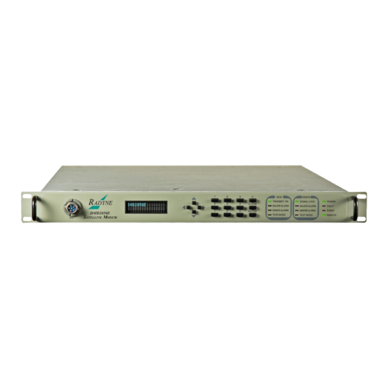
Chapter 1. Introduction Overview The new DMD2050E Satellite Modem (Figure 1-1) breaks new ground in flexibility and performance. The modulator has the ability to interoperate with military standards based upon MIL-STD-188-165A, MIL – STD-188-16B (Draft Standard), STANAG 4486 Edition 3, OM73 and support commercial standards that include IDR, IBS and DVB. -
Page 32: Dmd2050E Configurations
• feature upgrades • hardware options that the user can install at their own location • options that are installed to a unit that is sent to a Comtech EF Data facility • 1.2.1 Features Duplex modem operation • Data rates up to 52 Mbps •... -
Page 33: Advanced Forward Error Correction And Modulation
DMD2050E Universal Product Modem Introduction Switchable between spur-free 70/140 MHz and L-Band operations • AC or DC Power Input • Functions in virtually all Military and Commercial Satellite IP, Telecom, Video and Internet • applications Military standards include: • MIL-STD-188-165A STANAG 4486 Edition 3 •... -
Page 34: Interfaces
DMD2050E Universal Product Modem Introduction 1.2.4 Interfaces Industry-standard interfaces include: MIL-188-114 (EIA-530) • EIA-613 (HSSI) • 10/100/1000 Base T Gigabit Ethernet Bridge • Additional features defined by STANAG 4486 include Serial, Ethernet and Asynchronous overhead data multiplexing and demultiplexing. 1.2.5 Remote Control and Monitoring The DMD2050E has a Vacuum Fluorescent Display (VFD) on the front panel. -
Page 35: Dimensional Envelope
DMD2050E Universal Product Modem Introduction 1.2.7.1 Dimensional Envelope MN-DMD2050E Revision 2 1– 5... -
Page 36: Configurations And Options
On site – Using approved procedures, authorized personnel install hardware options on site • Service center - Send a unit to a Comtech EF Data service center for option installation • Feature upgrades - Operators install software options on site using an access code entered •... -
Page 37: Chapter 2. Installation
Step Procedure Inspect all shipping cartons for damage. Note: If damage exists, contact the freight company and Comtech EF Data immediately. Cut the tape at the top of the carton. Remove the packing material that covers the equipment. Remove the equipment. -
Page 38: Installation Safety
DMD2050E Universal Satellite Modem Installation Installation Safety The unit is shipped fully assembled. Do not remove the covers when you install the unit. WARNING SHOCK HAZARD - There are no user-serviceable parts or configuration settings inside the DMD2050E chassis. There is a shock hazard at the internal power supply module. -
Page 39: Location
DMD2050E Universal Satellite Modem Installation 2.3.1 Location The unit is intended for indoor use only. Do not install the unit in an unprotected outdoor location. Direct contact with rain, snow, wind or sun causes damage to the unit. Do not put units above high heat or an EMF generator. High heat and EMF have an unwanted effect on output signals and receive operations. -
Page 40: Cables
DMD2050E Universal Satellite Modem Installation 2.3.5 Cables To meet EMC directives, make sure to use shielded cables that have the shield terminated to the conductive backshells. To meet low voltage directives, use cables that have insulation flammability ratings of 94 VO or better. CAUTION Before you install the mating connectors, first make sure to start the unit and set the Interface Type (MIL-188-114A, G.703, etc.) from the front panel. -
Page 41: Modulator Checkout
DMD2050E Universal Satellite Modem Installation IMPORTANT Strap Code 26 can set the following modem configuration. The Frequency and Modulator Output Power are set independently of the strap code. See also: Appendix I. Strap Codes Modulator Checkout Make sure that the unit is installed near applicable electrical power and supporting equipment. 2.5.1 Initial Start Up Typically, new units are shipped from the factory with the Transmit Carrier set to OFF. - Page 42 DMD2050E Universal Satellite Modem Installation BLANK PAGE MN-DMD2050E Revision 2 2–6...
-
Page 43: Chapter 3. Theory Of Operation
Chapter 3. Theory of Operation DMD2050E Hardware The DMD2050E is based on a two printed circuit card (minimum configuration) design with additional optioned printed circuit cards available for additional features. The minimum configuration consists of an L-Band/IF Assembly and a Digital Baseband Assembly. The optional printed circuit cards include a Turbo Codec printed circuit card and one of several types of Interface printed circuit card (refer to Appendix A). -
Page 44: Dmd2050E L-Band/If Printed Circuit Card
DMD2050E Universal Satellite Modem Theory of Operation 3.1.1 DMD2050E L-Band/IF Printed Circuit Card The L-Band/IF Printed Circuit Card consists of an analog modulation function, an analog complex downconversion, and two wide-band digital synthesizers. The block diagram of the L-Band/IF Assembly is shown in Figure 3-2. Figure 3-2. -
Page 45: Dmd2050E Baseband Processing Printed Circuit Card
DMD2050E Universal Satellite Modem Theory of Operation 3.1.2 DMD2050E Baseband Processing Printed Circuit Card The advent of million-plus gate count FPGAs, advanced logic synthesis tools, and DSPs providing hundreds of MIPs enabled the design of a software configurable modem. Large, fast FPGAs now provide designers with what is essentially an on the fly programmable ASIC. -
Page 46: Figure 3-3. Dmd2050E Baseband Processing Card Block Diagram
DMD2050E Universal Satellite Modem Theory of Operation Figure 3-3. DMD2050E Baseband Processing Card Block Diagram The Baseband Printed Circuit Card also contains the Monitor and Control (M&C) Circuitry responsible for: Programmable part setup and initialization • Continuous control and adjustment of some functions •... -
Page 47: Enhanced Interface Printed Circuit Card
DMD2050E Universal Satellite Modem Theory of Operation The M&C System is based on a powerful microprocessor with a large amount of Flash memory. Several bus architectures are used to interconnect the M&C to all components of the DMD2050E. Communication to the outside world is done via connections to the remote port, terminal port, Ethernet port, and alarm ports. -
Page 48: Tx Baseband Processing
DMD2050E Universal Satellite Modem Theory of Operation Figure 3-4. DMD2050E Universal Satellite Modem Functional Block Diagram 3.2.3 Tx Baseband Processing The Tx Data and Clock enters the Baseband Processor, passes through a Rate Adapting FIFO and enters the Framer/Drop Processor. In Closed-Net Mode, the data passes through the framer unaltered. -
Page 49: Rx Baseband Processing
DMD2050E Universal Satellite Modem Theory of Operation The Reed-Solomon Encoder, encodes the data into Reed-Solomon Blocks. The blocks are then interleaved and synchronized to the frame pattern as defined by the selected specification (IESS- 308, IESS-309, DVB, etc.). After Reed-Solomon Encoding, the composite data and clock are applied to the BB Loopback Circuit. -
Page 50: Terminal Port
DMD2050E Universal Satellite Modem Theory of Operation Modem Status, Alarms & Contact Closures (Section 3.2.9) • 3.2.6 Terminal Port This port supports an asynchronous control protocol as described in Chapter 4. It is configured to support RS-232 signal levels. This port is intended for use in computer-based remote M&C. All functions of the modem may be monitored and controlled from this port via a common terminal connected to the Terminal Port. -
Page 51: Ethernet M&C Port
DMD2050E Universal Satellite Modem Theory of Operation 3.2.8 Ethernet M&C Port This port is dedicated for Ethernet Communications supporting SNMP, FTP and Web Browser. The port is configured for 10 Base-T communications protocols. The Ethernet M&C Interface requires a standard RJ45 Male connector. See also: Appendix D, Web Interface Setup Guide Appendix F, TCP/IP Ethernet Setup... -
Page 52: Internal Clock
DMD2050E Universal Satellite Modem Theory of Operation Internal Clock The time and date is kept in order to ‘time-tag’ system events. User can change the Internal Clock via the front panel, Web Browser or Terminal ports. Loopback Features (Terrestrial & IF) The modem provides for a number of different loopbacks. -
Page 53: Figure 3-5. Loopback Functional Block Diagram
DMD2050E Universal Satellite Modem Theory of Operation Figure 3-5. Loopback Functional Block Diagram MN-DMD2050E Revision 2 3–11... -
Page 54: Figure 3-6. Loopback Functional Block Diagram
DMD2050E Universal Satellite Modem Theory of Operation Figure 3-6. Loopback Functional Block Diagram MN-DMD2050E Revision 2 3–12... -
Page 55: Dmd2050E Clocking Options
DMD2050E Universal Satellite Modem Theory of Operation Figure 3-7. Loopback Functional Block Diagram DMD2050E Clocking Options The following paragraphs define the types of clocking options available to the user at the Front Panel of the DMD2050E. Refer to Figure 3-8 for clocking and polarity. 3.5.1 Clock Selection The modem supports a number of different clocking options that can be recovered from the... -
Page 56: Tx Clock Options
DMD2050E Universal Satellite Modem Theory of Operation INVERT NONE INV. TERR&BASE INV. BASEBAND INV. TERR DATA DATA POLARITY CLOCK & MODULATION SCTE DATA Tx CLK CLK POL NORMAL INVERTED HIGH STABILITY High Stability Oscillator AUTO INTERNAL REF FREQ EXTERNAL SCT CLK EXT REF TRANSMIT RECEIVE... -
Page 57: Scte: Serial Clock Transmit External
DMD2050E Universal Satellite Modem Theory of Operation 3.5.2.1 SCTE: Serial Clock Transmit External The SCTE clock is the Transmit Terrestrial Clock associated with the data interface. SCTE is an external clock received from the terrestrial equipment and the modem utilizes the terrestrial clock to lock the internal clock. -
Page 58: Rx Buffer Clock Options
DMD2050E Universal Satellite Modem Theory of Operation 3.5.3 RX Buffer Clock Options The modem supports a number of RX Buffer clock options that can be recovered from the satellite, terrestrial links, internally or externally. The various clocking options allow users to determine which clock will best fit their applications. -
Page 59: Sct: Serial Clock Transmit
DMD2050E Universal Satellite Modem Theory of Operation 3.5.3.3 SCT: Serial Clock Transmit If SCT clock is selected as the RX Buffer clock source, then it should be configured for internal. SCT is sometimes referred to as Internal Timing or Send Timing (ST). 3.5.3.4 EXT CLK/EXT BNC: External Clock, J16 The External Clock that can be selected as the RX Buffer clock source. -
Page 60: Transmit Timing Options
DMD2050E Universal Satellite Modem Theory of Operation Transmit Timing Options As shown in Figure 3-7, Transmit Terrestrial Data enters the modem and is clocked into a dejitter FIFO. Data is clocked out of the FIFO by the Modulator Clock. The Modulator Clock and Phase- Locked Loop (PLL), in conjunction with the Dejitter FIFO, reduces the input jitter. -
Page 61: Ethernet Data Interface (Optional)
DMD2050E Universal Satellite Modem Theory of Operation 3.6.4 Ethernet Data Interface (Optional) The modem support a single port 10/100/1000 Base T Interface. When this interface is selected additional menus will be displayed. Refer to Appendix H for interface set up and description of supporting features. -
Page 62: Ebem Framing Unit
DMD2050E Universal Satellite Modem Theory of Operation Ebem Framing Unit The DMD2050E EBEM framing Unit provides the ability to multiplex both Serial (MIL-STD-188- 114A or Hgh Speed Serial Interface – HSSI) with Bridged Ethernet payload, overhead and embedded channel data within the over-the-air transport stream. 3.8.1 DMD2050E Information Throughput Adpatation (ITA) Refer to Appendix I for additional information. -
Page 63: Fips Transec Module
DMD2050E Universal Satellite Modem Theory of Operation 3.10 FIPs TRANSEC Module The DMD2050E FIPS Security Module provides bulk encryption and decryption of traffic over the satellite that conforms to Security Level 2 as defined in FIPS PUB 140-2 using NIST approved 256-bit AES encryption (Advanced Encryption Standard). -
Page 64: Figure 3-9. Traffic Encryption Key Negotiation
DMD2050E Universal Satellite Modem Theory of Operation TX OFF Need to make timers configurable Idle Event: Timer MnC initiated Mailbox message to Event: TX ON Expired FIPs Action: None Action: Return to Idle FIPs initiated mailbox message to Waiting for MnC, MnC responds back once embedded channel is up or timeout Embedded... -
Page 65: Figure 3-10. Traffic Decryption Key Negotiation
DMD2050E Universal Satellite Modem Theory of Operation Startup MnC needs to mail the overriding state of the decryption to the FIPs may not be enabvled Event: KA Received, Encryption Not Enabled Idle Action: Send Key Agreement NACK Lynyx sets everyone up to start the Event: Key Agreement Message (KA) Received decryption process, the TRANSEC Action: Create Key Agreement Response (KAR) Message, Send KAR Message,... -
Page 66: Key Agreement Algorithm
DMD2050E Universal Satellite Modem Theory of Operation 3.10.1.2 Key Agreement Algorithm The key agreement algorithm used to negotiate a shared secret is the Ephemeral Unified Model, Elliptic Curve Cryptography Cofactor Diffie-Hellman C(2,0,ECC CDH) as specified in the elliptic curve parameters section of NIST SP 800-56A(3). 3.10.1.2.1 Key Derivation Once the shared secret has been negotiated, the TEK is generated from the shared secret using... -
Page 67: Figure 3-11. Transec Secure Web Browser Configuration Page
DMD2050E Universal Satellite Modem Theory of Operation After you have enabled Encryption from the front panel, set up the Encryption Control parameters. 1. Use the secure web interface (Figure 3-11) or the handheld key-loader (Figure 3-12) to enter Encryption Control parameters. 2. -
Page 68: Doubletalk Carrier-In-Carrier Option
Comtech EF Data has added a new dimension to satellite communication optimization: DoubleTalk Carrier-in-Carrier. MN-DMD2050E Revision 2... -
Page 69: What Is Doubletalk Carrier-In-Carrier
“Adaptive Cancellation.” Raytheon Applied Signal Technology uses the term DoubleTalk®, and Comtech EF Data refers to it as DoubleTalk® Carrier-in-Carrier® (CnC). CnC was first introduced in Comtech EF Data products in the CDM-Qx Satellite Modem and, more recently, in the CLO-10 Link Optimizer. - Page 70 DMD2050E Universal Satellite Modem Theory of Operation The transponder needs to be “bent-pipe” – meaning no on-board processing, demodulation, • regeneration can be employed. Demodulation/remodulation does not preserve the linear combination of the forward and return signals and the resulting reconstituted waveform prevents recovery of the original constituent signals.
-
Page 71: Operational Guidelines
DMD2050E Universal Satellite Modem Theory of Operation DMD2050E CnC Module DMD2050E Figure 3-13. Conceptual Block Diagram In a number of ways, CnC carriers behave similar to conventional carriers in satellite links. They are both exposed to adjacent carriers, cross-polarization and rain fade, and exhibit impairments when any of these become too great. -
Page 72: System Functionality And Operational Considerations
DMD2050E Universal Satellite Modem Theory of Operation The ratio of power spectral density is normally less than 11 dB; • modems modulators only demodulators only CnC operates with – not • In addition, to minimize ‘false’ acquisition, observe the following: Use of IESS-315 V.35 Scrambler is highly recommended;... -
Page 73: Figure 3-15. Same Link Using Dmd2050E And Doubletalk Carrier-In-Carrier
DMD2050E Universal Satellite Modem Theory of Operation Figure 3-11 shows the same link using the DMD2050E equipped with the DoubleTalk Carrier-in- Carrier option. Note that now only 50% of the bandwidth is being used, as now both carriers are occupying the same bandwidth. The transponder downlinks the composite signal containing both carriers on the same band to the DMD2050E which then translates the signal to near baseband where it can be filtered (decimated) and then processed as a complex envelope signal. -
Page 74: Table 3-1. Spectral Efficiency Using Doubletalk Carrier-In-Carrier
DMD2050E Universal Satellite Modem Theory of Operation Traditional Full Duplex Link Duplex Link with DoubleTalk Carrier-in-Carrier Figure 3-16. Duplex Link Optimization Because acquiring the delay and frequency offset of the interfering carrier is fundamentally a correlation operation, anything deterministic in the interfering carrier (within the correlation window of the algorithm) will potentially produce false correlation peaks and result in incorrect delays and/or frequency. -
Page 75: Doubletalk Carrier-In-Carrier Cancellation Process
DMD2050E Universal Satellite Modem Theory of Operation QPSK 3/4 1.50 3.00 QPSK 7/8 1.75 3.50 8-QAM 2/3 2.00 4.00 8-QAM 3/4 2.25 4.50 8-QAM 7/8 2.63 5.25 16-QAM 3/4 3.00 6.00 16-QAM 7/8 3.50 7.00 As shown here, DoubleTalk Carrier-in-Carrier allows equivalent spectral efficiency using a lower order modulation and/or FEC Code Rate;... -
Page 76: Figure 3-17. Doubletalk Carrier-In-Carrier Signals
DMD2050E Universal Satellite Modem Theory of Operation Figure 3-17. DoubleTalk Carrier-in-Carrier Signals Referring to Figure 3-5: Modem 1 and Modem 2 transmit signals S1 and S2 respectively. The satellite receives, translates, and retransmits the composite signal. The downlink signals S1* and S2*, received at Modem 1 and Modem 2 differ from the transmit signals primarily in terms of phase, frequency, and delay offsets. -
Page 77: Margin Requirements
DMD2050E Universal Satellite Modem Theory of Operation Unwanted interfering signal suppression of 30 dB or more has been achieved in commercial products with minimal degradation of the demodulator performance. 3.11.6 Margin Requirements Typical interfering signal cancellation is 28 to 35 dB (depending on the product). The residual interfering signal appears as noise causing a slight degradation of the Eb/No. -
Page 78: Symmetric Data Rate Link
DMD2050E Universal Satellite Modem Theory of Operation involves trying different FEC and modulation combinations with Carrier-in-Carrier until an optimal combination is found. For optimal Carrier-in-Carrier performance, it is recommended that the two carriers have similar symbol rate and power. This can be achieved by selecting appropriate MODCODs as shown in following sections. - Page 79 DMD2050E Universal Satellite Modem Theory of Operation Carrier-in-Carrier link design involved trying different Modulation & FEC Code Rates to find the optimal combination: 8-QAM, LDPC 2/3 with Carrier-in-Carrier • QPSK, LDPC 3/4 with Carrier-in-Carrier • QPSK, LDPC 2/3 with Carrier-in-Carrier •...
- Page 80 DMD2050E Universal Satellite Modem Theory of Operation Link parameters and LST summary for QPSK, LDPC 2/3 with Carrier-in-Carrier is as follows: MN-DMD2050E Revision 2 3–38...
-
Page 81: Asymmetric Data Rate Link
DMD2050E Universal Satellite Modem Theory of Operation The link budget summary for the different MODCOD combinations is as follows: Savings Allocated BW Leased BW Modulation & FEC Compared Ratio (MHz) (MHz) (MHz) to Original (dB) 8-QAM, LDPC 0.3584 1.1468 1.1468 -20% QPSK, LDPC 3/4 0.47785... - Page 82 DMD2050E Universal Satellite Modem Theory of Operation While the traditional link was based on QPSK, TPC 3/4 and required 3.9 MHz of leased bandwidth, the Carrier-in-Carrier link was based on QPSK, LDPC 3/4 and QPSK, LDPC 1/2 and required 2.8 MHz of leased bandwidth.
-
Page 83: Power Limited Links
DMD2050E Universal Satellite Modem Theory of Operation 3.11.9.3 Power Limited Links Carrier-in-Carrier can provide substantial savings even when the original link is power limited. Spreading the carrier by using a lower modulation and/or FEC along with the latest FEC can substantially reduce the total power which can then be traded with bandwidth using Carrier-in- Carrier. -
Page 84: Carrier-In-Carrier Commissioning And Deployment
DMD2050E Universal Satellite Modem Theory of Operation Whereas the original link used 8-PSK TPC 3/4, the Carrier-in-Carrier link used QPSK STANAG TURBO 7/8. The savings summary is as follows: Item Original Link With Carrier-in-Carrier and Savings STANAG TURBO 7/8 Hub to Remote To Total Hub to Remote... - Page 85 DMD2050E Universal Satellite Modem Theory of Operation Step Procedure Make sure CnC function is OFF at both sites. Using a spectrum analyzer, measure Co+No/No at the input to the modem at Site A. Using a spectrum analyzer, measure Co+No/No at the input to the modem at Site B. Measure/record Eb/No at Site B.
-
Page 86: Validating Carrier-In-Carrier Performance
DMD2050E Universal Satellite Modem Theory of Operation 3.11.11 Validating Carrier-in-Carrier Performance Carrier-in-Carrier performance can be easily validated by verifying that Eb/No degradation because of Carrier-in-Carrier is within published specification for the observed Power Spectral Density Ratio. The following steps are recommended for validating Carrier-in-Carrier performance: Step Procedure Set up a conventional side-by-side link of the desired Eb/No:... -
Page 87: Operational References
DMD2050E Universal Satellite Modem Theory of Operation 3.11.12 Operational References 3.11.12.1 Carrier-in-Carrier Link Budget Calculation The following steps are required for calculating the link budget for a Carrier-in-Carrier Link: Step Procedure Calculate the link budget for both carriers in the duplex link, with required CnC margin: Find the Eb/No corresponding to the desired BER Add CnC Margin... -
Page 88: Estimating Psd Ratio
DMD2050E Universal Satellite Modem Theory of Operation 3.11.12.2 Estimating PSD Ratio PSD can be estimated from a link budget using Downlink EIRP and Symbol Rate: PSD = Downlink EIRP – 10 * Log (Symbol Rate) PSD Ratio Example: Carrier Downlink EIRP Symbol Rate Power Spectral Density A to B... -
Page 89: Estimating Psd Ratio From Satmaster
DMD2050E Universal Satellite Modem Theory of Operation 3.11.12.4 Estimating PSD Ratio from Satmaster 3.11.12.5 Estimating PSD Ratio Using Spectrum Analyzer PSD Ratio or CnC Ratio can also be estimated using a Spectrum Analyzer capable of integrating the signal power in a given bandwidth. CnC Ratio (in dB) = Power (in dBm) –... -
Page 90: Doubletalk Carrier-In-Carrier Specifications
DMD2050E Universal Satellite Modem Theory of Operation 3.11.13 DoubleTalk Carrier-in-Carrier Specifications Operating Mode Requires the two links to share a common carrier frequency (Outbound and Inbound symbol rates do not have to be equal) Power Spectral Density Ratio and BSPK/QPSK/8-PSK/8-QAM: –7 dB to +11 dB (ratio of power spectral density, CnC Ratio outbound interferer to desired inbound) 16-QAM: –7 dB to +7 dB (ratio of power spectral density, outbound interferer... -
Page 91: Carrier-In-Carrier Summary
Theory of Operation 3.11.14 Carrier-in-Carrier Summary Comtech EF Data’s DoubleTalk Carrier-in-Carrier can provide significant savings in operational expenses. The following should be considered when evaluating DoubleTalk Carrier-in-Carrier: DoubleTalk Carrier-in-Carrier can only be used for full duplex links where the transmitting •... - Page 92 DMD2050E Universal Satellite Modem Theory of Operation Leased bandwidth Almost all satellite operators charge for the Leased Bandwidth (LBW). Leased Bandwidth or Leased Resource is the greater of the Allocated Bandwidth and Power Equivalent Bandwidth. For example, if a carrier requires 3 MHz of Allocated BW and 4.5 MHz of PEB, the Leased Bandwidth is 4.5 MHz Power Spectral Density (PSD) Power Spectral Density (PSD) is the signal power per unit bandwidth: dBW / Hz...
-
Page 93: Tpc And Low Density Parity Check (Ldpc) Coding
DMD2050E Universal Satellite Modem Theory of Operation C/N = C/N – 10 log B [where B is bandwidth in Hz] = C/N – 10 log R [where R is data rate in bits/sec] = C/N + 10 log B – 10 log R = C/N –... -
Page 94: Ldpc Versus Tpc
Eb/No than 8-PSK. Comtech’s implementation of 8-QAM is the subject of a U.S. Patent, granted in 2007. Comtech EF Data chose the CDM-600 platform as the first satellite modem in which to implement both LDPC and 8-QAM, and the DMD2050E includes a newer technology version of the original design. -
Page 95: Table 3-2. Available Tpc And Ldpc Modes
1/2 to 0.95, both an LDPC and a TPC codec need to be offered. In order to meet this requirement, Comtech EF Data has developed a combination LDPC/TPC Codec module that can be added to the DMD2050E Modem. Table 3-2 outlines the operating modes provided by this module. - Page 96 Please contact the Sales Department at Comtech EF Data for pricing and delivery information. Table 3-3 compares all TPC and LDPC modes available in Comtech EF Data’s DMD2050E, and shows Eb/No performance and spectral efficiency (occupied bandwidth) for each case. This information will be of particular interest to satellite operators wishing to simultaneously balance transponder power and bandwidth.
-
Page 97: Table 3-3. Comparison Of All Comtech Ef Data Tpc And Ldpc Modes
DMD2050E Universal Satellite Modem Theory of Operation Table 3-3. Comparison of all Comtech EF Data TPC and LDPC Modes (DMD2050E with LDPC/TPC Codec) Eb/No at Eb/No at Spectral Efficiency Occupied * Bandwidth Mode BER = 10 BER = 10 Symbol Rate... -
Page 98: Tpc And Ldpc Summary
DMD2050E Universal Satellite Modem Theory of Operation 3.12.2 TPC and LDPC Summary AGAINST Exceptionally good BER performance – significant improvement compared with every other FEC method in use today. Most modes have no pronounced threshold effect – fails gracefully. Exceptional bandwidth efficiency . Nothing! Coding gain independent of data rate (in this implementation). -
Page 99: Reed-Solomon Code Rate
DMD2050E Universal Satellite Modem Theory of Operation When the signal is received and demodulated by the Receiving Modem, it is fed to a Viterbi Decoder for the first layer of error correction. After error correction is performed by the Viterbi Decoder, the unique words are located and the data is deinterleaved and reformed into blocks. -
Page 100: Dmd2050E Automatic Uplink Power Control (Aupc Operation)
DMD2050E Universal Satellite Modem Theory of Operation Table 3-4. Reed-Solomon Codes Type of Data Rate R-S Code (n, Bandwidth Expansion Interleaving Maximum R-S Codec Service (Kbps) k, t) [ (n/k) -1 ] Depth Delay (ms) Small IDR (126, 112, 7) 0.125 (With 16/15 (126, 112, 7) -
Page 101: Table 3-5. Baud Rate Examples
DMD2050E Universal Satellite Modem Theory of Operation rate through the modem. The overhead channel is recovered at the far end. This added channel is termed variously “An Overhead Channel”, ”Service Channel”, “Async Channel” or in IESS terminology an “ES to ES Data Channel.” The basic frame structure used by the multiplexer is that specified in the IESS-309 Standard, resulting in a 16/15 Aggregate t0 through-Data Ratio. -
Page 102: Standard Ibs Mode
DMD2050E Universal Satellite Modem Theory of Operation Standard IBS Enhanced Mode Kbps Kbps Baud Rate Example Baud Rate Example 19200 19200 1024 19200 1088 19200 1152 19200 1216 19200 1280 19200 1344 19200 1408 19200 1472 19200 1536 19200 1600 19200 1664 19200... -
Page 103: Asynchronous Multiplexer Mode
DMD2050E Universal Satellite Modem Theory of Operation The ratio of the Through Terrestrial Data Channel Rate to the aggregate rate is 15/16. The standard transmit and receive channels of the ES to ES Data Channel in Standard IBS Mode are raw channels operating at the specific bit rate as controlled by the data channel rate, without buffering. -
Page 104: To Disable The Esc Backward Alarms
DMD2050E Universal Satellite Modem Theory of Operation The user can connect whichever systems on the earth stations that they desire to these Backward Alarms Relays as long as they will supply ground to the Backward Alarm Relay Input in the “no fault” condition and the ground will be removed in the “faulted” condition. For example: the user could connect the Demod Summary Fault of the modem to the Backward Alarm 1 Input, so that if the demod went into Major Alarm (such as a Carrier Loss), Backward Alarm 1 would be transmitted to the receive end of the link. -
Page 105: Figure 3-22. 1 To 3 Control Ratio
DMD2050E Universal Satellite Modem Theory of Operation The number of user data slots and control words per frame is selected by the SCC Control Ratio Parameter. This can be any value from 1 to 1 through 1 to 7. A higher ratio allows a lower overhead rate but since there are less Sync Words, there is a higher acquisition time. -
Page 106: Aggregate Data Rate
DMD2050E Universal Satellite Modem Theory of Operation 3.19.2 Aggregate Data Rate The aggregate data rate equals the following: User Data Rate + In-Band Rate + Synchronizing Overhead Rate Because SCC must adjust the overhead so that there are an equal number of user data bits in each slot, the synchronizing overhead cannot be easily calculated. -
Page 107: Overhead Rate Comparison
DMD2050E Universal Satellite Modem Theory of Operation 3.19.3 Overhead Rate Comparison The SCC Overhead Ratio varies depending on the User Data Rate, the In-Band Rate, and the Control Ratio. This gives SCC the advantage of lower overhead rates when compared to IBS, which has a fixed overhead ratio of 16/15 or 1.067. -
Page 108: Actual Overhead Rate Calculation
DMD2050E Universal Satellite Modem Theory of Operation 3.19.4 Actual Overhead Rate Calculation The following is the actual calculation the modem does to calculate the overhead ratio: 1. The modem calculates the minimum in-band rate to limit the size of the user data slots to 2,500 bits (the result is truncated to an integer). -
Page 109: Scc Overhead Channel Setup
DMD2050E Universal Satellite Modem Theory of Operation 3.20 SCC OVERHEAD CHANNEL SETUP 1. Set the Framing Mode (located under Mod and Demod Data Menus) to SCC. After doing this, two new menus will appear to the right of the Framing Menu, for both the Mod and Demod. - Page 110 DMD2050E Universal Satellite Modem Theory of Operation 9. The physical connection to the DMD2050E for the overhead channel will be the DB-9 Female Port labeled ASYNC (J17). SCC Overhead Chart Examples (Viterbi 3/4 w/V.35 Scrambler) Modem Data Rate Kbps SCC Control Channel Rate In-Band Overhead Rate Setting Symbol Rate 6800...
-
Page 111: Locating The Dmd2050E Id Code Operational Procedure
Unique ID codes let you add feature upgrades to the unit. You do not have to return the unit to the factory. After you purchase new features, Comtech EF Data gives you a new ID code. Enter the new ID code into the unit to activate the new features. - Page 112 DMD2050E Universal Satellite Modem Theory of Operation BLANK PAGE MN-DMD2050E Revision 2 3–70...
-
Page 113: Chapter 4. User Interfaces
Chapter 4. User Interfaces User Interfaces The DMD2050E has three interfaces available for typical operations: Front Panel • Remote Port • Terminal • Front Panel Interface Figure 4-1 shows the front panel. Table 4-1 describes each of the functional areas: Vacuum Fluorescent Display (VFD) •... -
Page 114: Vfd - Vacuum Fluorescent Display
DMD2050E Universal Satellite Modem User Interfaces Table 4-1. Front Panel Functions Area Function Shows operating parameters and configuration data Arrow Keys Controls the up, down, right and left cursor position on the display Numeric Keys Allows entry of data LED Lights Shows the status of the unit, see section 4.2.4. -
Page 115: Led Lights
DMD2050E Universal Satellite Modem User Interfaces Parameter Type 0 – 9 Clear & Clear & Move Move IP Address Change Digit Increase Digit Decrease Digit left right Clears left of Change Increase Decrease Move Move Clears right of Text Strings... -
Page 116: Parameter Setup
DMD2050E Universal Satellite Modem User Interfaces Parameter Setup 4.3.1 Select a Parameter Use the arrow keys to move through the menus. To select a parameter, press ENTER. The first space of the parameter flashes to show it is selected. Figure 4-2. Enter New Parameters 4.3.2 Enter and Save a New Parameter Use the numeric keys to enter new data into the parameter. -
Page 117: Modulator Main Menu And Parameters
DMD2050E Universal Satellite Modem User Interfaces 4.4.1 MODULATOR Main Menu and Parameters 4.4.1.1 NETWORK SPEC (menu) The NETWORK SPEC command activates a group of preset parameters. These preset parameters help reduce keystrokes and potential compatibility problems. NETWORK SPEC {MIL 188-165A, EBEM, IDR, IBS, DROP & INSERT, CLOSED NET, DVB} NETWORK SPECS and data rates must be compatible. -
Page 118: Strap Code
DMD2050E Universal Satellite Modem User Interfaces 4.4.1.2 STRAP CODE The STRAP CODE is another means for quickly setting several parameters at one time. STRAP CODE parameters include: Data Rate Inner Code Rate • • Satellite Framing Scrambler • • Drop and Insert Outer Code Rate (Reed-Solomon) •... - Page 119 DMD2050E Universal Satellite Modem User Interfaces DATA MENU Trellis (8PSK) {2/3} TPC (BPSK) {5/16, 21/44} ≤ 20Mbps TPC (OQPSK/QPSK) {1/2, 3/4, 7/8} ≤ 20Mbps TPC (8PSK/8QAM) {3/4, 7/8} TPC (16QAM) {3/4, 7/8} DVB VIT {2/3, 5/6} DVB Trellis {3/4, 5/6, 7/8, 8/9} LDPC (B/O/QPSK) {1/2, 2/3, 3/4} LDPC (8PSK/8QAM)
-
Page 120: Ebem Network Spec Parameters
DMD2050E Universal Satellite Modem User Interfaces DATA MENU TERR FRAMING {NONE, 188, 204} DVB Only DATA POLARITY {INV. TERR & BASE, INV. Invert the Tx Data polarity. BASEBAND, INV.TERR DATA, NONE} BPSK SYMBOL PAIR {NORMAL, SWAPPED} BPSK Mode Only Swap the I & Q Channels. ESC OVERHEAD {VOICE X2, DATA 64KBPS} IDR ESC Channel is used for Voice or 64 K data... -
Page 121: Reed-Solomon (Menu)
DMD2050E Universal Satellite Modem User Interfaces 4.4.1.5 REED-SOLOMON (menu) IMPORTANT When Reed-Solomon is selected, these parameters are available. ENABLE/DISABLE {ENABLED, DISABLE} Enable or disable the Reed-Solomon Encoder. RS RATE {Refer to Table 3-1 for valid Displays the currently used n, k Reed-Solomon Codes. In n/k values} Closed Net Mode, you can select custom R-S Codes. -
Page 122: Local Aupc (Menu)
DMD2050E Universal Satellite Modem User Interfaces 4.4.1.7 LOCAL AUPC (menu) NOTE When modems are configured for Radyne AUPC, the remote Eb/No is displayed in the Monitor Menus. LOCAL AUPC MENU AUPC MODE {DISABLED, NEAR SIDE, DISABLED: Enable or disable the Local AUPC Function of RADYNE, EFDATA} the local modem. - Page 123 DMD2050E Universal Satellite Modem User Interfaces LOCAL AUPC MENU MINIMUM TX POWER {0 to -45 dB} Set the minimum Transmit Power. EBEM: When configured for EBEM AUPC, the minimum Transmit Power is the lowest power setting that will be used when the remote modem commands a decrease of the Transmit Power from the Local modem.
- Page 124 DMD2050E Universal Satellite Modem User Interfaces LOCAL AUPC MENU TARGET Eb/No {4.0 to 16 dB} Set the desired E for the local receiver. RADYNE AUPC: When configured for Radyne AUPC, this setting is compared against the remote E and commands to the local modem to increase or decrease the local transmit power.
-
Page 125: Remote Aupc (Menu)
DMD2050E Universal Satellite Modem User Interfaces 4.4.1.8 REMOTE AUPC (menu) NOTE Remote AUPC Menus are available only when the modem is configured for EF AUPC. REMOTE AUPC MENU AUPC MODE {DISABLE,NEAR SIDE, Enable or disable the AUPC Function of the remote modem. The EFDATA} remote AUPC Function is the response of the local modem to commands for an increase or decrease of the Transmit Power in... -
Page 126: Demodulator Main Menu And Parameters
DMD2050E Universal Satellite Modem User Interfaces 8PSK 2/3 {NOT SELECTED, SELECTED} Used to select the mod/code rate 8PSK 3/4 {NOT SELECTED, SELECTED} Used to select the mod/code rate 8PSK 7/8 {NOT SELECTED, SELECTED} Used to select the mod/code rate 8PSK 19/20 {NOT SELECTED, SELECTED} Used to select the mod/code rate 16APSK 1/2... -
Page 127: Strap Code
DMD2050E Universal Satellite Modem User Interfaces Closed Net All possible combinations are allowed. NOTE: DVB settings require the DVB NETWORK SPEC and EBEM settings require the EBEM NETWORK SPEC. 4.4.2.2 STRAP CODE The STRAP CODE is another means for quickly setting several parameters at one time. STRAP CODE parameters include: Data Rate Inner Code Rate... -
Page 128: Data (Menu)
DMD2050E Universal Satellite Modem User Interfaces IF MENU INPUT THRESHOLD {-30 to –90} Sets the minimum carrier receive level when a carrier drops (dBm) below this level. The modem will sweep and try to acquire a new signal. This prevents extremely small carriers from falsely locking the modem. -
Page 129: Reed-Solomon (Menu)
DMD2050E Universal Satellite Modem User Interfaces DATA MENU SCRAMBLER SEL {NONE, V.35-IESS, V.35 CITT, V.35 EF, IBS Select the descrambler type. w/Optional Framing and optional Reed- Solomon, Reed-Solomon Scrambler w/Optional Framing, CCITT, V.35FC, OM-73, V.35EF_RS, TPC SCRAMBLER (Turbo Codec), DVB, EDMAC, EBEM} SCRAMBLER CTRL {ENABLED, DISABLE} Enable or disable the descrambler... -
Page 130: Cnc (Menu)
DMD2050E Universal Satellite Modem User Interfaces 4.4.2.6 CNC (menu) IMPORTANT When the Carrier-in-Carrier option is installed, these parameters are available. ® Enable/Disable {Enabled, Disabled} Enable or disable the CnC. MIN SRCH DELAY {Minimum Search Delay (ms), 0 to Max} MAX SRCH DELAY {Maximum Search Delay (ms), Min to 330ms} FREQ OFFST RNG {Range of Frequency Offset (KHz) between the... -
Page 131: Interface Main Menu And Parameters
DMD2050E Universal Satellite Modem User Interfaces 4.4.3 INTERFACE Main Menu and Parameters 4.4.3.1 TX SETUP (menu) TX SETUP MENU CIRCUIT ID Enter a Tx Circuit Identifier. Circuits can be given up to an 11 Character alphanumeric identity such as LINK1. TERR INTERFACE {RS423 SERIAL, M2P PARALLEL, DVB Select the Transmit Interface Type. - Page 132 DMD2050E Universal Satellite Modem User Interfaces IMPORTANT When Ethernet Interface is selected or EBEM Network specification is enabled, these parameters are available. ETH FLOW CONTROL {Disabled, Disable or enable flow control. Only visible when Ethernet is selected as the interface type. Enabled} ETH DAISY CHAIN {Disabled, Port...
-
Page 133: Drop & Insert (Menu)
DMD2050E Universal Satellite Modem User Interfaces 4.4.3.1.1 DROP & INSERT (menu) DROP & INSERT MENU DROP MODE {NONE, T1-D4, Select any mode from the list. T1-ESF, PCM-30, PCM-30C, PCM-31, PCM-31C, T1-D4-S, T1-ESF-S.} MAP COPY {SRC Map to Dest Copy drop and insert maps. Tx ACT map is the drop map currently Map} being used by the modem. -
Page 134: Rx Setup (Menu)
DMD2050E Universal Satellite Modem User Interfaces 4.4.3.2 RX SETUP (menu) RX SETUP MENU CIRCUIT ID Enter the Rx Circuit Identifier. Circuits can be as DLINK1 TERR INTERFACE {RS423 SERIAL, M2P Select the Receive Type. PARALLEL, DVB PARALLEL, G.703 E2, G.703 T2 BAL, G.703 T2 UNBAL, G.703 E1 BAL, G.703 E1 UNBAL, G.703 T1 AMI, G.703 T1... -
Page 135: Drop & Insert (Menu)
DMD2050E Universal Satellite Modem User Interfaces 4.4.3.2.1 DROP & INSERT (menu) INSERT MODE {NONE, T1-D4, Select any mode from the list. T1-ESF, PCM-30, PCM-30C, PCM-31, PCM-31C, T1-D4-S, T1-ESF-S.} T1/E1 FRAME SRC {INTERNAL, Selects the frame source for T1 or E1 framing. EXTERNAL, Note: IDI/DDO loop is an internal loopback of the terrestrial clocks not IDI/DDO... -
Page 136: General (Menu)
DMD2050E Universal Satellite Modem User Interfaces 4.4.3.3 GENERAL (menu) GENERAL MENU EXT FREQ (MHz) {Variable Through Data Rate} Select the external clock frequency in MHz. REF FREQ SRC {EXTERNAL, HIGH STABILITY} Select the Frequency Reference Source. REF FREQ (MHz) Select the reference clock frequency in MHz. BB RELAYS {IBS ALMs, IBS/MNR ALMs, IBS ALMs: Only supports IBS prompt and service alarms. -
Page 137: Link Status (Menu)
DMD2050E Universal Satellite Modem User Interfaces MONITOR MENU CORRECTED BER The CBER display shows an estimated corrected bit error rate of the modem. Depending on the symbol rate the modem is running, the high-end performance scale of this display will vary (10 E , 10 or 10 ). - Page 138 DMD2050E Universal Satellite Modem User Interfaces NOTE Port status indicators are: Down: The link is down. Unresolved: Unable to agree on connection speed. 10 Mbps Half: Connected at 10 Base-T Half Duplex. 10 Mbps Full: Connected at 10 Base-T Full Duplex. 100 Mbps Half: Connected at 100 Base-T Half Duplex.
-
Page 139: Voltages (Menu)
DMD2050E Universal Satellite Modem User Interfaces 4.4.4.2 VOLTAGES (menu) VOLTAGES MENU TEMPERATURE Displays internal temperature. +1.5V RX SUPPLY Displays the measured voltage of the 1.5 Volt Rx power bus located inside the modem. +1.5V TX SUPPLY Displays the measured voltage of the 1.5 Volt Tx power bus located inside the modem. +3.3V SUPPLY Displays the measured voltage of the +3.3 Volt power bus located inside the modem. -
Page 140: Alarms Main Menu And Parameters
DMD2050E Universal Satellite Modem User Interfaces 4.4.5 ALARMS Main Menu and Parameters Alarm details are described in Chapter 6, Maintenance and Troubleshooting. CAUTION Masked alarms can cause unwanted effects in the performance of the unit. CURRENT See Chapter 6, Maintenance and Troubleshooting for more data about alarms. LATCHED These alarms are latched to catch intermittent failures: BACKWARD... -
Page 141: Terminal (Menu)
DMD2050E Universal Satellite Modem User Interfaces 4.4.6.3 TERMINAL (menu) TYPE {VT-100, WYSE50, VIEWPOINT} Select the emulation type. BAUD RATE {150, 300, 600, 1200, 2400, 4800, 9600, 19200, 38400, Enter the terminal baud rate. 57600, 115200} 4.4.6.4 REMOTE PORT (menu) ADDRESS {32 - 255} Enter the Remote Port Multidrop Address. - Page 142 DMD2050E Universal Satellite Modem User Interfaces TCP/IP MENU BOOTp SERVER {128 – 257, Only used if Bootp is selected in Boot Mode. Should be consistent default is 206} with the tag expected by the users Bootp Server. MODEM HOST The Host Modem for the network. IP ADDR MASK {XXX.XXX.XXX.XXX} The IP Address Mask of the local network.
-
Page 143: Snmp (Menu)
DMD2050E Universal Satellite Modem User Interfaces 4.4.6.6 SNMP (menu) A description of OID organization is provided in the MIB portion of this manual (Appendix C). SNMP MENU SNMP VERSION {V1 & V2, V3} This selection controls the SNMP Version that will be used in messaging between the equipment and it’s host. -
Page 144: Ftp (Menu)
DMD2050E Universal Satellite Modem User Interfaces 4.4.6.7 FTP (menu) PORT {XXXX} Select the desired port number. Factory default is set to 21. Port 21 is a reserved port utilized by the File Transfer Protocol for FTP control traffic. USER ID Enter the user identification for access to an FTP session. -
Page 145: Transec (Menu)
DMD2050E Universal Satellite Modem User Interfaces 4.4.6.9 TRANSEC (menu) TRANSEC MENU IP ADDR MASK {XXX.XXX.XXX.XXX} The IP Address Mask of the TRANSEC Module. The mask is expressed in a hexadecimal format, and must be a valid TCP/IP Mask. This field should be set before changes are made to the Modem or Router Address. -
Page 146: Main Board (Menu)
DMD2050E Universal Satellite Modem User Interfaces 4.4.6.10.1 MAIN BOARD (menu) NOTE Only the applicable VCO adjustment screens are displayed. IMPORTANT These fields are protected to prevent accidental changes. To change a field, press all four arrow keys at the same time. INT VCO ADJUST {0% - 100%} Adjusts the internal frequency reference for calibration. -
Page 147: Features (Menu)
DMD2050E Universal Satellite Modem User Interfaces CNC BOARD (menu) Indicates the part number for the CNC Board. DEBUG MODE {ENABLED, DISABLED} CNC DEBUG REGS1 Used for factory test only. CNC DEBUG REGS2 Used for factory test only. CNC DEBUG REGS3 Used for factory test only. -
Page 148: Test Main Menu And Parameters
DMD2050E Universal Satellite Modem User Interfaces 4.4.7 TEST Main Menu and Parameters TEST MENU TX TEST PATTERN {NONE, 2047, 2^15-1, 2^23-1} Enables the tests listed above. RX TEST PATTERN {NONE, 2047, 2^15-1, 2^23-1} Enables the tests listed above. PATTERN SYNC {YES, NO} Yes indicates that the RX Test Pattern is in sync. - Page 149 DMD2050E Universal Satellite Modem User Interfaces TEST MENU IQ SAMPLING {ENABLE/DISABLE} Enables the I & Q pattern on the Web Browser Interface. IQ SPCTRM SMPLING {ENABLE, DISABLE} Enables the Frequency Spectrum pattern on the Web Browser. ICMP PING {NONE, BOOTp SERVER, Used to ping the Router TRAP AGENT, TCP/IP ROUTER}...
-
Page 150: Terminal Mode Control
DMD2050E Universal Satellite Modem User Interfaces Terminal Mode Control The Terminal Mode Control lets you use an external terminal or computer to monitor and control the unit. Typically, the Control Port is the RS–232 Serial Interface connection to the terminal device. -
Page 151: Setup For Terminal Mode
DMD2050E Universal Satellite Modem User Interfaces For numerical input, use the number keys to input the data. Press ENTER to save the data. To cancel numerical input before you save it, press ESC. NOTE Using an invalid input key causes the terminal to show an error message. 4.5.3 Setup for Terminal Mode NOTE When you use the terminal for the first time, use the $ (dollar) character to reset the... - Page 152 DMD2050E Universal Satellite Modem User Interfaces BLANK PAGE MN-DMD2050E Revision 2 4–40...
-
Page 153: Chapter 5. External Connections
Chapter 5. External Connections Figure 5-1. DMD2050E Universal Satellite Modem Front Panel Figure 5-2. DMD2050E Rear Panel Figure 5-3. DMD2050E Rear Panel Configurations MN-DMD2050E Revision 2 5–1... -
Page 154: Power Connectors, Ground And Switches
DMD2050E Universal Satellite Modem External Connections Power Connectors, Ground and Switches The DMD2050E units have either AC or DC power connectors (see Figure 5-3). Power Type Location Prime Power Maximum Power Consumption Rear panel 100 – 240 VAC, 50 – 60 Hz Rear panel 48V ±... -
Page 155: Front Panel Connections
DMD2050E Universal Satellite Modem External Connections Front Panel Connections 5.2.1 Key Loader Interface Label Location Description Connector Type Front Panel Key Loader Interface Port RS-232, 6-pin audio connector (GC283) Connect a hand-held PC to the Key Loader Interface to upload the Shared Message Authentication Token (SMAT) to the modem. -
Page 156: Rear Panel Connectors
DMD2050E Universal Satellite Modem External Connections Rear Panel Connectors CAUTION Before you connect any cable to the unit, examine the connector labels. Make sure to use the correct mating connector when you connect a cable to the unit. 5.3.1 HSSI / Ethernet Connectors Label Description Connector Type... -
Page 157: Ext Ref (J10)
DMD2050E Universal Satellite Modem External Connections 5.3.2 EXT REF (J10) Label Description Connector Type Input Levels Frequencies (MHz) EXT REF J10 External Reference Port 50 Ohm Female BNC 0.3 to 5 Vpp (Sine or Square wave) 1.544 2.048 10.0 5.3.3 IF Connectors (Transmit and Receive) J11, J12, J13, J14 IF Frequencies Power Levels Connector... -
Page 158: Alarm (J15)
DMD2050E Universal Satellite Modem External Connections 5.3.4 ALARM (J15) Label Description Connector Type ALARM J15 Alarm Port 15-pin Female D The Alarm port uses contact closures to identify the status of the unit. Pins 1 through 6 supply Form C contacts for major alarm status on the modulator and demodulator. Normally Open or Normally Closed conditions indicate a FAULTED or OFF state. -
Page 159: Ibs Network Alarms Configuration
DMD2050E Universal Satellite Modem External Connections 5.3.4.1 IBS Network Alarms Configuration IBS Prompt Alarms IBS Service Alarms Pins 7 through 9 Pins 10 through 12 Includes Includes TX Minor Alarms or RX Minor Alarms or TX Minor Alarm and TX Major Alarms RX Minor Alarms and RX Major Alarms 5.3.4.2 Closed Net Alarms Configuration... -
Page 160: Async (J17)
DMD2050E Universal Satellite Modem External Connections 5.3.6 ASYNC (J17) Label Description Connector Type ASYNC J17 Asynchronous Data Interface Port 9-pin Female D Table 5-5. Pinouts for J17 ASYNC Port 9-pin Female D Connector Pin No. Signal Name Signal Direction Receive Data B RXD_B Output Receive Data A... -
Page 161: Mil-188-114A (J19)
DMD2050E Universal Satellite Modem External Connections 5.3.8 MIL-188-114A (J19) Label Description Connector Type MIL-188-114A J19 EIA-530 Port (RS-422) 25-pin Female D Table 5-6. Pinouts for J19 MIL-188-114A Port 25-pin Female D Connector Pin No. Signal Name Signal Direction Shield Send Data A (-) SD-A Input Receive Data A (-) -
Page 162: Table 5-6. Pinouts For J20 Remote Port (Rs-485 Or Rs-232) 9-Pin Female D Connector
DMD2050E Universal Satellite Modem External Connections 5.3.9 Monitor and Control Connectors J20, J21 Label Description Connector Type REMOTE J20 Remote Monitor and Control Port (RS-485 or RS-232) 9-pin Female D ETHERNET J21 Ethernet Monitor and Control Port Female RJ-45 Table 5-7. Pinouts for J20 REMOTE Port (RS-485 or RS-232) 9-pin Female D Connector Pin No. -
Page 163: Chapter 6. Maintenance And Troubleshooting
Chapter 6. Maintenance and Troubleshooting Periodic Maintenance 6.1.1 Battery Replacement WARNING: DANGER OF EXPLOSION if the battery is incorrectly replaced. The unit contains a Lithium Battery. Replace it with an equivalent battery that is specified by the manufacturer. Dispose of used batteries in compliance with local and national regulations. -
Page 164: Troubleshooting
DMD2050E Univeral Satellite Modem Maintenance and Troubleshooting Troubleshooting 6.2.1 Basic Troubleshooting Procedures 1) Make sure all interface signals are correct. 2) If the unit is not operating correctly, replace it with an equivalent unit that is known to operate correctly. 3) If replacing the unit does not correct the problem, examine the power supply and electrical wiring for problems. -
Page 165: Alarms
DMD2050E Univeral Satellite Modem Maintenance and Troubleshooting Alarms 6.3.1 Major Transmit Alarms Alarm Description Status FPGA CFG A transmit FPGA hardware failure exists. {Pass/Fail, Unmasked/Masked} DSP CFG A transmit FPGA failure exists. {Pass/Fail, Unmasked/Masked} SCT Clock PLL The Tx SCT Clock PLL is not locked. This alarm flashes on {Pass/Fail, during certain parameter changes. -
Page 166: Minor Tx Alarms
DMD2050E Univeral Satellite Modem Maintenance and Troubleshooting Alarm Description Status INPUT LVL THRESH Indicates the Rx level has fallen below the input threshold level. {Pass/Fail, Marked/Unmarked} FRAME LOCK The Framing Unit cannot find the expected framing pattern. {Pass/Fail, Unmasked/Masked} MULTIFRAME LOCK The Framing Unit cannot find the expected framing pattern. -
Page 167: Minor Rx Alarms
DMD2050E Univeral Satellite Modem Maintenance and Troubleshooting Alarm Description Status TPC CONFLICT CHK Indicates that the TPC parameters are not configured correctly. {Pass/Fail, (only visible when TPC enabled) Unmasked/Masked} 6.3.3.1 Minor Rx Alarms Alarm Description Status BUFF UNDERFLOW A Doppler Buffer underflow occurred. {Pass/Fail, Unmasked/Masked} BUFF NEAR EMPTY... -
Page 168: Drop And Insert Alarms
DMD2050E Univeral Satellite Modem Maintenance and Troubleshooting Alarm Description Status RX AGC LEVEL Indicates Rx level is below allowable limits. {Pass/Fail, Unmasked/Masked} IBS BER More than 1 in 1000 bits in error exist in IBS mode. {Pass/Fail, Unmasked/Masked} RX DVB FRAME LOCK The Rx Satellite Data Stream Framing is not DVB. - Page 169 DMD2050E Univeral Satellite Modem Maintenance and Troubleshooting Alarm Description Status +3.3V SUPPLY Shows the measured voltage of the +3.3 Volt power bus {Pass/Fail, inside the modem. Unmasked/Masked} +5V SUPPLY Shows the measured voltage of the +5 Volt power bus inside {Pass/Fail, the modem.
-
Page 170: Alarm Masks
DMD2050E Univeral Satellite Modem Maintenance and Troubleshooting Alarm Masks The DMD2050E self-monitors and isolates faults. Alarms for these faults are categorized as: Active Alarms Common Equipment Alarms Backward Alarms CAUTION Masked alarms can cause unwanted effects in the performance of the unit. You can mask certain alarms. -
Page 171: Common Equipment Alarms
DMD2050E Univeral Satellite Modem Maintenance and Troubleshooting Alarms are grouped into transmit and receive alarms. Transmit and receive alarms are completely independent of each other. 6.4.2 Common Equipment Alarms Common equipment alarms occur when the unit has problems that affect both transmit and receive operations. - Page 172 DMD2050E Univeral Satellite Modem Maintenance and Troubleshooting RX MAJOR (menu) {Pass/Fail} RX MINOR (menu) {Pass/Fail} MULTIFRAME LOCK SAT AIS LB SYNTH PLL DnI FRAME LOCK IF SYNTH PLL DnI M-FRAME LOCK ETHERNET WAN INSERT CRC T1/E1 SIGNALING IFEC LOCK TPC CONFLICT CHK OFEC LOCK INTERLEAVER RS UNCORR.
-
Page 173: Backward Alarms
DMD2050E Univeral Satellite Modem Maintenance and Troubleshooting NOTE These alarms show the status of the alarms RECEIVED FROM the distant satellite end. IDR1 SAT ALARM 1 {PASS, FAIL} IDR1 SAT ALARM 2 {PASS, FAIL} IDR1 SAT ALARM 3 {PASS, FAIL} IDR1 SAT ALARM 4 {PASS, FAIL} IBS SAT ALARM... -
Page 174: Ibs Alarms And Actions
DMD2050E Univeral Satellite Modem Maintenance and Troubleshooting IBS Alarms and Actions Figure 6-1 and Table 6-1show the IBS alarms and actions to be taken at the earth station, the terrestrial data stream and the satellite. These alarms include those detected on the terrestrial link and those detected from the satellite. -
Page 175: Chapter 7. Technical Specifications
Chapter 7. Technical Specifications Modulator Modulator Specifications Modulation BPSK, QPSK, OQPSK, 8-PSK, 8-QAM, 16-QAM, 16-APSK IF Tuning Range 50 to 90, 100 to 180 MHz in 1 Hz Steps L-Band Tuning Range 950 to 2050 MHz in 1 Hz Steps Impedance IF, 50 Ohm (75 Ohm Optional) L-Band, 50 Ohm... -
Page 176: Demodulator
DMD2050E Universal Satellite Modem Technical Specifications Modulator Specifications Turbo (16-QAM) {3/4, 7/8} ≤ 20Mbps DVB VIT {2/3, 5/6} DVB Trellis {3/4, 5/6, 7/8, 8/9} LDPC (BPSK) {1/2} LDPC (OQPSK/QPSK) {1/2, 2/3, 3/4} LDPC (8-PSK/8-QAM) {2/3, 3/4} LDPC (16-QAM) {3/4} STANAG Turbo (B/QPSK) {1/2, 2/3, 3/4, 7/8, 19/20, None} STANAG Turbo (8-PSK) {1/2, 2/3, 3/4, 7/8, 19/20, None}... -
Page 177: Plesiochronous Buffer
DMD2050E Universal Satellite Modem Technical Specifications Demodulator Specifications Turbo (OQPSK/QPSK) {1/2, 3/4, 7/8} ≤ 20Mbps Turbo (8-PSK/8-QAM) {3/4, 7/8} ≤ 20Mbps Turbo (16-QAM) {3/4, 7/8} ≤ 20Mbps DVB VIT {2/3, 5/6} DVB Trellis {3/4, 5/6, 7/8, 8/9} LDPC (BPSK) {1/2} LDPC (OQPSK/QPSK) {1/2, 2/3, 3/4} LDPC (8-PSK/8-QAM) -
Page 178: Terrestrial Interfaces
DMD2050E Universal Satellite Modem Technical Specifications Terrestrial Interfaces MIL-188-114A, HSSI GiGE 10/100/1000 Base-T IBS/Synchronous Interface (Standard) MIL-188-144A/RS-422/-530 All Rates, Differential, Clock/Data, DCE High-Speed Serial Interface (HSSI) & Gigi Ethernet Data Interface HSSI HSSI, Serial, 50-Pin SCSI-2 Type Connector (Female) Ethernet Data Interface One RJ-45, Auto-Crossover, Auto-Sensing, 10/100/1000 Ethernet Data Ports. -
Page 179: Data Rate Limits
DMD2050E Universal Satellite Modem Technical Specifications 7.11 Data Rate Limits 7.11.1 Non-DVB Non-DVB Data Rate Limits Modulation Code Rate Min Data Rate Max Data Rate BPSK NONE 4800 10000000 BPSK VIT 1/2 2400 10000000 BPSK VIT 3/4 3600 10000000 BPSK VIT 7/8 4200 10000000... - Page 180 DMD2050E Universal Satellite Modem Technical Specifications Non-DVB Data Rate Limits Modulation Code Rate Min Data Rate Max Data Rate OQPSK NONE 9600 20000000 OQPSK VIT 1/2 4800 20000000 OQPSK VIT 3/4 7200 20000000 OQPSK VIT 7/8 8400 20000000 OQPSK SEQ 1/2 4800 2048000 OQPSK...
-
Page 181: Dvb
DMD2050E Universal Satellite Modem Technical Specifications 7.11.2 DVB Data Rate Limits Modulation Code Rate DVB Mode Min Data Rate Max Data Rate BPSK VIT 1/2 187 Mode 2400 4583333 BPSK 188 Mode 2400 4607843 BPSK 204 Mode 2400 5000000 BPSK VIT 2/3 187 Mode 2934... - Page 182 DMD2050E Universal Satellite Modem Technical Specifications DVB Data Rate Limits Modulation Code Rate DVB Mode Min Data Rate Max Data Rate 8-PSK TRE 8/9 187 Mode 11550 20000000 8-PSK 188 Mode 11797 20000000 8-PSK 204 Mode 12800 20000000 16-QAM TRE 3/4 187 Mode 13200 20000000...
-
Page 183: Ber Specifications
DMD2050E Universal Satellite Modem Technical Specifications 7.12 BER Specifications 7.12.1 BER Performance (Viterbi) 1E-1 B/O/QPSK Uncoded Theory 1E-2 Viterbi Decoder 1E-3 Typical Performance 1E-4 1E-5 1E-6 Specification 1/2 Rate Specification 3/4 1E-7 Rate Specification 7/8 1E-8 Rate 1E-9 Eb/No in dB Figure 7-1. -
Page 184: Ber Performance (Sequential)
DMD2050E Universal Satellite Modem Technical Specifications 7.12.2 BER Performance (Sequential) 1E-1 B/O/QPSK Uncoded Theory 1E-2 Sequential Decoder Typical Performance 1E-3 1E-4 1E-5 1E-6 Specification 1/2 Rate 1E-7 Specification 3/4 Rate 1E-8 Specification 7/8 Rate 1E-9 Eb/No in dB Figure 7-2. DMD2050E B/O/QPSK BER Performance (Sequential) Note: Eb/No values include the effect of using differential decoding and v.35 descrambling. -
Page 185: Ber Performance (Viterbi With Reed-Solomon)
DMD2050E Universal Satellite Modem Technical Specifications 7.12.3 BER Performance (Viterbi with Reed-Solomon) 1E-1 B/O/QPSK Uncoded Theory 1E-2 Typical Viterbi Decoder Reed Performance Solomon 1E-3 1E-4 1E-5 1E-6 Specification 1/2 Rate 1E-7 Specification 7/8 Rate Specification 3/4 Rate 1E-8 1E-9 Eb/No in dB Figure 7-3. -
Page 186: Ber Performance (Turbo)
DMD2050E Universal Satellite Modem Technical Specifications 7.12.4 BER Performance (Turbo) 1E-1 B/O/QPSK Uncoded Theory 1E-2 Turbo Decoder Typical Performance 1E-3 1E-4 1E-5 1E-6 1E-7 Specification Turbo 0.495 1E-8 Specification Turbo 0.793 1E-9 Eb/No in dB Figure 7-4. DMD2050E B/O/QPSK BER Performance (Turbo) Note: Eb/No values include the effect of using interleaving and maximum iterations. -
Page 187: Ber Performance (8Psk Trellis)
DMD2050E Universal Satellite Modem Technical Specifications 7.12.5 BER Performance (8PSK Trellis) 1E-1 8PSK Uncoded Theory Trellis 1E-2 Decoder 1E-3 Typical Performance 1E-4 1E-5 1E-6 Specification 2/3 Rate 1E-7 Specification 2/3 Rate w/RS 1E-8 1E-9 Eb/No in dB Figure 7-5. DMD2050E 8PSK BER Performance (Trellis) Note: Eb/No values include the effect of using differential decoding and v.35 descrambling. -
Page 188: Ber Performance (8Psk Turbo)
DMD2050E Universal Satellite Modem Technical Specifications 7.12.6 BER Performance (8PSK Turbo) 1E-1 8PSK Uncoded Theory Turbo Decoder 1E-2 Typical Performance 1E-3 1E-4 1E-5 1E-6 1E-7 1E-8 Specification Turbo 0.793 1E-9 Eb/No in dB Figure 7-6. DMD2050E 8PSK BER Performance (Turbo) Note: Eb/No values include the effect of using interleaving and maximum iterations. -
Page 189: Ber Performance (16Qam Viterbi)
DMD2050E Universal Satellite Modem Technical Specifications 7.12.7 BER Performance (16QAM Viterbi) 1E-1 16QAM Uncoded Theory Viterbi 1E-2 Decoder 1E-3 Typical Performance 1E-4 1E-5 1E-6 Specification 3/4 Rate 1E-7 Specification 7/8 Rate 1E-8 1E-9 Eb/No in dB Figure 7-7. DMD2050E 16QAM BER Performance (Viterbi) Note: Eb/No values include the effect of using differential decoding and v.35 descrambling. -
Page 190: Ber Performance (16Qam Viterbi With Reed-Solomon)
DMD2050E Universal Satellite Modem Technical Specifications 7.12.8 BER Performance (16QAM Viterbi with Reed-Solomon) 1E-1 16QAM Uncoded Theory 1E-2 Viterbi Decoder - Reed Solomon Typical 1E-3 Performance 1E-4 1E-5 1E-6 Specification 1E-7 3/4 Rate w/RS Specification 7/8 Rate w/RS 1E-8 1E-9 Eb/No in dB Figure 7-8. -
Page 191: Ber Performance (16Qam Turbo)
DMD2050E Universal Satellite Modem Technical Specifications 7.12.9 BER Performance (16QAM Turbo) 1E-1 16QAM Uncoded Theory 1E-2 Turbo Decoder Typical Performance 1E-3 1E-4 1E-5 1E-6 Turbo 0.495 1E-7 Turbo 0.793 1E-8 1E-9 Eb/No in dB Figure 7-9. DMD2050E 16QAM BER Performance (Turbo) Note: Eb/No values include the effect of using interleaving and maximum iterations. -
Page 192: Ber Performance (Oqpsk Turbo)
DMD2050E Universal Satellite Modem Technical Specifications 7.12.10 BER Performance (OQPSK Turbo) 1E-1 B/O/QPSK Uncoded Theory 1E-2 Turbo Decoder Specification 3/4 Rate 1E-3 1E-4 Specification Specification 1/2 Rate 7/8 Rate 1E-5 1E-6 1E-7 Typical Performance 1E-8 1E-9 Eb/No in dB Figure 7-10. DMD2050E OQPSK BER Performance (Turbo) MN-DMD2050E Revision 2 7–18... -
Page 193: Ber Performance (Bpsk Turbo)
DMD2050E Universal Satellite Modem Technical Specifications 7.12.11 BER Performance (BPSK Turbo) 1E-1 B/O/QPSK Uncoded Theory 1E-2 Turbo Decoder 1E-3 1E-4 Specification 21/44 Rate 1E-5 Specification 1E-6 5/16 Rate 1E-7 Typical Performance 1E-8 1E-9 Eb/No in dB Figure 7-11. DMD2050E BPSK BER Performance (Turbo) MN-DMD2050E Revision 2 7–19... -
Page 194: Ber Performance (8Psk Turbo)
DMD2050E Universal Satellite Modem Technical Specifications 7.12.12 BER Performance (8PSK Turbo) 1E-1 8PSK Uncoded Theory 1E-2 Turbo Decoder Specification 3/4 Rate 1E-3 Specification 7/8 Rate 1E-4 Typical Performance 1E-5 1E-6 1E-7 1E-8 1E-9 Eb/No in dB Figure 7-12. DMD2050E 8PSK BER Performance (Turbo) MN-DMD2050E Revision 2 7–20... -
Page 195: Ber Performance (16Qam Turbo)
DMD2050E Universal Satellite Modem Technical Specifications 7.12.13 BER Performance (16QAM Turbo) 1E-1 16QAM Uncoded Theory Turbo Decoder 1E-2 Specification 3/4 Rate Specification 7/8 1E-3 Rate 1E-4 Typical Performance 1E-5 1E-6 1E-7 1E-8 1E-9 Eb/No in dB Figure 7-13. DMD2050E 16QAM BER Performance (Turbo) MN-DMD2050E Revision 2 7–21... -
Page 196: B/O/Qpsk Ber Performance (Ldpc)
DMD2050E Universal Satellite Modem Technical Specifications 7.12.14 B/O/QPSK BER Performance (LDPC) 1E-1 B/O/QPSK Uncoded Theory 1E-2 LDPC Decoder 1E-3 Specification 1/2 Rate Specification 2/3 Rate 1E-4 Specification 3/4 Rate 1E-5 Typical Performance 1E-6 1E-7 1E-8 1E-9 Eb/No in dB Figure 7-14. DMD2050E B/O/QPSK BER Performance (LDPC) MN-DMD2050E Revision 2 7–22... -
Page 197: 8Psk / 8Qam Ber Performance (Ldpc)
DMD2050E Universal Satellite Modem Technical Specifications 7.12.15 8PSK / 8QAM BER Performance (LDPC) 1E-1 8PSK Uncoded Theory 1E-2 LDPC Decoder 1E-3 1E-4 Typical Performance 8QAM Rate 2/3 Specification 1E-5 8PSK Rate 2/3 Specification 1E-6 8PSK/8QAM Rate 3/4 Specification 1E-7 1E-8 1E-9 Eb/No in dB Figure 7-15. -
Page 198: 16Qam Ber Performance (Ldpc)
DMD2050E Universal Satellite Modem Technical Specifications 7.12.16 16QAM BER Performance (LDPC) 1E-1 16QAM Uncoded Theory 1E-2 LDPC Decoder 1E-3 1E-4 Typical Performance Specification 1E-5 3/4 Rate 1E-6 1E-7 1E-8 1E-9 Eb/No in dB Figure 7-16. DMD2050E 16QAM BER Performance (LDPC) MN-DMD2050E Revision 2 7–24... -
Page 199: Ber Performance B/O/Qpsk (Milstd 188-165B Or Stanag) Turbo
DMD2050E Universal Satellite Modem Technical Specifications 7.12.17 BER Performance B/O/QPSK (MILSTD 188-165B or STANAG) Turbo 1E-1 B/O/QPSK Uncoded Theory Specification 1/2 Rate 1E-2 Specification MILSTD 188-165B 2/3 Rate or STANAG Decoder 1E-3 Specification 3/4 Rate Specification 1E-4 7/8 Rate Specification 19/20 Rate 1E-5 1E-6... -
Page 200: Ber Performance 8-Psk (Milstd 188-165B Or Stanag) Turbo
DMD2050E Universal Satellite Modem Technical Specifications 7.12.18 BER Performance 8-PSK (MILSTD 188-165B or STANAG) Turbo 1E-1 Specification 8PSK Uncoded Theory 1/2 Rate MILSTD 188-165B Specification 1E-2 2/3 Rate or STANAG Decoder Specification 3/4 Rate Specification 7/8 Rate 1E-3 Specification 19/20 Rate 1E-4 1E-5 1E-6... -
Page 201: Ber Performance 16Apsk (Milstd 188-165B Or Stanag) Turbo
DMD2050E Universal Satellite Modem Technical Specifications 7.12.19 BER Performance 16APSK (MILSTD 188-165B or STANAG) Turbo 1E-1 Specification 16QAM Uncoded Theory 1/2 Rate Specification MILSTD 188-165B 2/3 Rate or STANAG Specification Decoder 1E-2 3/4 Rate Specification Specification 7/8 Rate 19/20 Rate 1E-3 1E-4 1E-5... - Page 202 DMD2050E Universal Satellite Modem Technical Specifications Table 7-1 - B/O/QPSK BER Performance (Viterbi) Specification Typical 1/2 Rate 3/4 Rate 7/8 Rate 1/2 Rate 3/4 Rate 7/8 Rate 1E-3 4.2 dB 5.3 dB 6.2 dB 3.9 dB 4.9 dB 5.8 dB 1E-4 4.8 dB 6.1 dB...
- Page 203 DMD2050E Universal Satellite Modem Technical Specifications Table 7-4 - B/O/QPSK BER Performance (Turbo) Specification Typical Turbo 0.495 Turbo 0.793 Turbo 0.495 Turbo 0.793 1E-3 2.5 dB 3.3 dB 2.2 dB 3 dB 1E-4 2.7 dB 3.7 dB 2.3 dB 3.2 dB 1E-5 3 dB 4.1 dB...
- Page 204 DMD2050E Universal Satellite Modem Technical Specifications Table 7-7 - 16QAM BER Performance (Viterbi) Specification Typical 3/4 Rate 7/8 Rate 3/4 Rate 7/8 Rate 1E-3 8.9 dB 10.3 dB 8.1 dB 9.5 dB 1E-4 9.8 dB 11.1 dB 9 dB 10.3 dB 1E-5 10.7 dB 11.9 dB...
- Page 205 DMD2050E Universal Satellite Modem Technical Specifications Table 7-10 - (O)QPSK BER Performance (Turbo) Specification Typical 1/2 Rate 3/4 Rate 7/8 Rate 1/2 Rate 3/4 Rate 7/8 Rate 1E-3 3.2 dB 4 dB 2.8 dB 3.7 dB 1E-4 3.4 dB 4.1 dB 3 dB 3.8 dB 1E-5...
- Page 206 DMD2050E Universal Satellite Modem Technical Specifications Table 7-14 - B/O/QPSK BER Performance (LDPC) Specification Typical 1/2 Rate 2/3 Rate 3/4 Rate 1/2 Rate 2/3 Rate 3/4 Rate 1E-5 2 dB 2.3 dB 3 dB 1.7 dB 2 dB 2.6 dB 1E-9 2.3 dB 2.7 dB...
- Page 207 DMD2050E Universal Satellite Modem Technical Specifications Table 7-18 - 8PSK BER Performance (MILSTD 188-165B or STANAG) Turbo Specification 16K Block Typical 16K Block 1/2 Rate 2/3 Rate 3/4 Rate 7/8 Rate 19/20 Rate 1/2 Rate 2/3 Rate 3/4 Rate 7/8 Rate 19/20 Rate 1E-3 3.6 dB 5.2 dB...
-
Page 208: Agc Output Voltage
DMD2050E Universal Satellite Modem Technical Specifications 7.13 AGC Output Voltage The AGC Output Voltage is a function of the Input Power Level in dBm. The AGC Output Voltage is found on the Alarm connector Pin 14 of J15. Figure 7-13. AGC Voltage Monitor MN-DMD2050E Revision 2 7–34... -
Page 209: Appendix A. Product Options
Appendix A. Product Options Hardware Options These enhanced interface cards are available: DC Input Prime Power Allows for an optional 48VDC Input Power Source DoubleTalk Carrier-in-Carrier (CnC) Allows for an optional CnC upgrade ® ® Custom Options Custom options are available for the DMD2050E. Get most custom options through firmware and software changes. - Page 210 DMD2050E Universal Satellite Modem Product Options BLANK PAGE MN-DMD2050E Revision 2 A–2...
-
Page 211: Appendix B. Front Panel Upgrades And Demonstration Mode
Appendix B. Front Panel Upgrades and Demonstration Mode Introduction The DMD2050E Universal Satellite Modem allows you to install feature demonstrations and permanent upgrades using the front panel. Demonstration upgrades operate only during a 30-day evaluation period. Purchased upgrades continue to operate as part of the permanent configuration. Required Equipment The unit is shipped fully assembled. -
Page 212: Record The Features And Options
DMD2050E Universal Satellite Modem Front Panel Upgrade Procedure B.3.1 Record the Features and Options Find and record the features and options that you want to add to the unit. 1. Go to the MAIN Menu. 2. Go to the SYSTEM Menu. 3. -
Page 213: Record The Unit Id
DMD2050E Universal Satellite Modem Front Panel Upgrade Procedure B.3.2 Record the Unit ID Comtech requests the Unit ID when you order an upgrade or a demonstration. Use the front panel to find and record the Unit ID: 1. Go to the MAIN Menu. 2. -
Page 214: Install The Code
DMD2050E Universal Satellite Modem Front Panel Upgrade Procedure B.3.4 Install the Code Use the front panel to enter this code and install the upgrade: 1. Go to the MAIN Menu. 2. Go to the SYSTEM Menu. 3. Go to the HW/FW CONFIG Menu. 4. -
Page 215: Demonstration Mode Considerations
DMD2050E Universal Satellite Modem Front Panel Upgrade Procedure B.3.5 Demonstration Mode Considerations The unit uses several indicators to show that it is in demonstration mode: TEST MODE LEDs Flash The MOD and DEMOD TEST MODE LEDs flash when the unit is operating in demonstration mode. -
Page 216: Cancel The Demonstration Mode
DMD2050E Universal Satellite Modem Front Panel Upgrade Procedure B.3.6 Cancel the Demonstration Mode IMPORTANT If you cancel the demonstration mode, the unit returns to operating with the former permanent configuration immediately. After a demonstration mode has been canceled, you cannot restart it with the same demonstration code. -
Page 217: Appendix C. Carrier Control
Appendix C. Carrier Control C.1 Carrier Control and Alarms If a TX major alarm occurs, modulator output is muted automatically. This automatic muting prevents the modulator from using an unknown spectrum and possibly disturbing adjacent carriers. To override an automatic muting of the output, mask the alarm that is causing the fault. This mask lets the transmission continue, even if the fault occurs. -
Page 218: Carrier States
DMD2050E Universal Satellite Modem Carrier Control C.3 Carrier States These are the carrier states: Carrier OFF Carrier VSAT • • Carrier ON Carrier RTS • • Carrier AUTO • You set the carrier states using the CARRIER menu. The path is: MODULATOR ... -
Page 219: Carrier Vsat
DMD2050E Universal Satellite Modem Carrier Control 2. The output starts again automatically. C.3.4 Carrier VSAT The carrier state is Carrier VSAT. You change the modulator output and the satellite footprint. If you use the front panel to make the change: 1. - Page 220 DMD2050E Universal Satellite Modem Carrier Control BLANK PAGE MN-DMD2050E Revision 2 C–4...
-
Page 221: Appendix D. Web Interface Setup Guide
Appendix D. Web Interface Setup Guide D.1 Introduction The web interface lets Radyne products connect and communicate through the Ethernet port. The connection is a 10Base-T Ethernet connection. You use the web interface to control and monitor the parameters and functions of these connected units. -
Page 222: Ip Address
DMD2050E Universal Satellite Modem Web Browser Setup Guide D.2.2 IP Address IMPORTANT Before you set an IP address, contact the IT authority in your organization for help. The BOOT MODE setting controls access to the IP address for the unit. The unit is shipped from the factory with the BOOT MODE set to DEFAULT (a fixed address that is not accessible). -
Page 223: User Account Data
DMD2050E Universal Satellite Modem Web Browser Setup Guide D.3.2 User Account Data IMPORTANT All entries are case-sensitive. Parameter Character type Maximum Minimum Restrictions User ID ASCII Printable Characters None Authentication Password ASCII Printable Characters None Web User ASCII Printable Characters None Access Group Access Level... -
Page 224: Edit The User Id
DMD2050E Universal Satellite Modem Web Browser Setup Guide IMPORTANT All entries are case-sensitive. To set up a User Account, do these steps: 1. Edit the User ID. 2. Edit the Access Group. 3. Edit the Authentication Password. D.1.1 Edit the User ID. 1. -
Page 225: Reset A User Account
DMD2050E Universal Satellite Modem Web Browser Setup Guide D.2 Reset a User Account Sometimes, it is necessary to reset a user account to the factory defaults. For example, a user account may be locked because of too many incorrect password attempts. Release the lock by resetting the user account. -
Page 226: Equipment Website
DMD2050E Universal Satellite Modem Web Browser Setup Guide D.4 Equipment Website Once you know that the modem is accessible through the internet, do these steps: 1. Start the internet browser. 2. Type the modem’s IP address in the address field, and then press [Enter]. The WEB browser equipment introduction page opens. -
Page 227: Log In To The Equipment Website
Other links are available on the Introduction page: Links to the PDF files that contain technical specifications and product options • Links to the Comtech EF Data website and customer service pages • D.4.1 Log in to the Equipment Website You must log in before you can go to other pages in the website. -
Page 228: D.5 Web Page Appearance
DMD2050E Universal Satellite Modem Web Browser Setup Guide D.5 Web Page Appearance This page displays the Monitor and Control section of the modem web interface. The page has an appearance that resembles the DMD2050E layout. The front panel display section of the page shows the current front panel alarm status of the modem. -
Page 229: Configure Web Browsers For The Radyne Web Interface
DMD2050E Universal Satellite Modem Web Browser Setup Guide D.6 Configure Web Browsers for the Radyne WEB Interface D.6.1 Configure Internet Explorer 9 for the Radyne WEB Interface Click the Compatibility View button on the address bar. When Compatibility View is active, the color of the button is blue. If Compatibility View is active, the Monitor &... -
Page 230: Change The Encoding
DMD2050E Universal Satellite Modem Web Browser Setup Guide D.6.2.1 Change the encoding: Click View on the Firefox menu bar. Select Character Encoding and click Western (ISO-8859-1). The page refreshes and shows the correct values. MN-DMD2050E Revision 2 D–10... -
Page 231: Install The Internet Explorer Tab V2 Add-On
DMD2050E Universal Satellite Modem Web Browser Setup Guide D.6.2.2 Install the Internet Explorer Tab V2 add-on The Internet Explorer (IE) Tab V2 add-on lets you open WEB browser pages in Internet Explorer 7 mode. The link to the add-on is https://addons.mozilla.org/en-US/firefox/addon/ie-tab- 2-ff-36/ Download and install IE Tab V2. -
Page 232: Configure Chrome For The Radyne Web Browser
DMD2050E Universal Satellite Modem Web Browser Setup Guide D.6.3 Configure Chrome for the Radyne WEB Browser When you open the Monitor & Control window, you may see the error message “This webpage is not available”. Click the Chrome address bar. Make sure the full address is highlighted, and then press Enter. -
Page 233: Change The Encoding
DMD2050E Universal Satellite Modem Web Browser Setup Guide D.6.3.1 Change the encoding On the Chrome address bar, click the wrench icon (Customize and Control Google Chrome). Go to Tools / Encoding and click Western (ISO-8859-1). The page refreshes and shows the correct values. -
Page 234: Install The Internet Explorer Tab For Chrome
DMD2050E Universal Satellite Modem Web Browser Setup Guide D.6.3.2 Install the Internet Explorer Tab for Chrome The Internet Explorer (IE) Tab lets you open WEB browser pages in Internet Explorer 7 mode. The link to install IE Tab is: https://chrome.google.com/webstore/search/IE%20Tab?utm_source=chrome-ntp-icon To install IE Tab, click + ADD TO CHROME next to IE Tab. -
Page 235: Configure Safari For The Radyne Web Browser
DMD2050E Universal Satellite Modem Web Browser Setup Guide D.6.4 Configure Safari for the Radyne WEB Browser IMPORTANT First, make sure to empty the browser cache. D.6.4.1 Empty the browser cache On the Safari menu bar, click Edit and then click Empty Cache... Click [Empty] on the confirmation popup window. -
Page 236: Reset The Ethernet M&C Port
DMD2050E Universal Satellite Modem Web Browser Setup Guide D.6.4.2 Reset the Ethernet M&C port To reset the Ethernet M&C port, either 1) cycle the electrical power OFF and ON, or, 2) re-enter the Modem IP Address. Re-entering the Modem IP Address avoids traffic disruption. D.6.4.3 Re-enter the Modem IP address 1. - Page 237 DMD2050E Universal Satellite Modem Web Browser Setup Guide On the Monitor & Control, Password Setup or IP Administration windows, some fields may be blank or contain Update. To correct the display, change the encoding. NOTE If you leave a window and return, it may be necessary to correct the display again. MN-DMD2050E Revision 2 D–17...
-
Page 238: Change The Encoding
DMD2050E Universal Satellite Modem Web Browser Setup Guide D.6.4.4 Change the encoding Click View on the Safari menu bar. Select Text Encoding and click Western European. (The Default selection is not applicable.) The page refreshes and shows the correct values. MN-DMD2050E Revision 2 D–18... -
Page 239: Configure Maxthon For The Radyne Web Browser
DMD2050E Universal Satellite Modem Web Browser Setup Guide D.6.5 Configure Maxthon for the Radyne WEB Browser On the Monitor & Control, Password Setup or IP Administration windows, some fields may be blank or contain Update. To correct the display, either 1) change the browser mode, or, 2) change the encoding. NOTE If you leave a window and return, it may be necessary to correct the display again. -
Page 240: Change The Browser Mode
DMD2050E Universal Satellite Modem Web Browser Setup Guide D.6.5.1 Change the browser mode Two browser modes are possible: Ultra Mode (default) Retro Mode Click the browser mode icon at the right of the address bar. Select Retro Mode . The page refreshes and shows the correct values. MN-DMD2050E Revision 2 D–20... -
Page 241: Change The Encoding
DMD2050E Universal Satellite Modem Web Browser Setup Guide D.6.5.2 Change the encoding On the Monitor & Control page, right click to open the browser menu. Select Encoding, and then click the encoding type that is already selected. The page refreshes and shows the correct values. - Page 242 DMD2050E Universal Satellite Modem Web Browser Setup Guide BLANK PAGE MN-DMD2050E Revision 2 D–22...
-
Page 243: Appendix E. Drop And Insert (Standard And Efficient Options
Appendix E. Drop and Insert (Standard and Efficient Options) E.1 Introduction Drop and Insert (D&I) functions let a full T1 or E1 terrestrial trunk and a fractional Nx64 Kbps satellite channel work together. The framing of the terrestrial trunk is specified in CCITT G.704. The D&I specifications agree with IBS, small IDR, and Radyne Proprietary Efficient D&I Framing Structures. -
Page 244: Configuration Examples
DMD2050E Universal Satellite Modem Efficient Drop and Insert Objective Menu Path Requirement Find the G.703 interface card status. SYSTEM 01-PLR5660 or AS/4975 HW/FW CONFIG (or equivalent) TERR INTFC BRD Find the Open Network Drop and SYSTEM D&I Insert status. HW/FW CONFIG INSTALLED (required) FEATURES... - Page 245 DMD2050E Universal Satellite Modem Efficient Drop and Insert Figure E-1. Looped Modems Figure E-2 Looped Modems with Separate D&I Trunks MN-DMD2050E Revision 2 E–3...
-
Page 246: Functional Descriptions
DMD2050E Universal Satellite Modem Efficient Drop and Insert E.4 Functional Descriptions E.4.1 Drop Only When Drop is enabled and Insert is disabled, the unit performs a drop-only function. Framed E1 or T1 Data is input via the Send Data In Port, the selected timeslots are dropped into the IBS frame structure, and the unaltered terrestrial data is output via the Send Data Out Port (see Figure E-3). - Page 247 DMD2050E Universal Satellite Modem Efficient Drop and Insert Figure E-4 Insert Only with Eternal Frame Source Figure E-5 Insert Only with Internal Frame Source MN-DMD2050E Revision 2 E–5...
-
Page 248: Data Formats
DMD2050E Universal Satellite Modem Efficient Drop and Insert E.4.3 Data Formats The terrestrial data formats compatible with D&I include: E1 Data T1 Data PCM-30 T1-D4 PCM-30C T1-ESF PCM-31 SLC-96 PCM-31C E.4.3.1 PCM-30 The PCM-30 Mode of Operation supports an E1 Interface with Multiframe Alignment (MFAS) and Channel Associated Signaling (CAS). -
Page 249: Pcm-31C
DMD2050E Universal Satellite Modem Efficient Drop and Insert drop and n timeslots to insert where n = 1, 2, 3, 4, 5, 6, 8, 10, 12, 15, 16, 20, 24, or 30. Because there is no implied ABCD signaling, the user is free to select timeslot 16 as a Drop Insert Timeslot. - Page 250 DMD2050E Universal Satellite Modem Efficient Drop and Insert SATCh Enter to Edit are not Any changes made in these displays are made on the screen, but entered into the modem. Once these menus are configured, the Mapping Menu must be used to actually enter the settings into the modem.
- Page 251 DMD2050E Universal Satellite Modem Efficient Drop and Insert Example : For a modem w/ Drop and Insert enabled at a data rate of 256 (with timeslots assigned 1 - 1, 2 - 2, etc.). At a data rate of 256, the modem will allow 4 channels to assign timeslots. Under the Tx Menu, assign the timeslots that are to be used to the 4 channels.
-
Page 252: Configuring The Modem For Drop And Insert
DMD2050E Universal Satellite Modem Efficient Drop and Insert Copy RX EDIT > RX ACTIVE Press <ENTER> to enter the settings into the modem. To View the current Timeslot Assignment: If there is a question of the channels not being entered properly, the Mapping Menu may be used to see how the channels/timeslots are configured in the modem. -
Page 253: Data Rate
DMD2050E Universal Satellite Modem Efficient Drop and Insert E.5.1 Data Rate Data Rate affects the Drop and Insert function in the following ways: It determines the number of Satellite Channels that will be displayed in the Edit Maps. • It contributes to the Operational Mode selection process. Trying to change the •... -
Page 254: Operational Network Specification
DMD2050E Universal Satellite Modem Efficient Drop and Insert n = 12, data rate = 768000 n = 15, data rate = 960000 n = 16, data rate = 1024000 n = 20, data rate = 1280000 n = 24, data rate = 1536000 n = 30, data rate = 1920000 (valid with E1 Interface only) E.5.2 Operational Network Specification The Network Specification of the Modem often determines which additional menus and displays... -
Page 255: Insert Terrestrial Frame Source
DMD2050E Universal Satellite Modem Efficient Drop and Insert E.5.3.1 Insert Terrestrial Frame Source The Insert Terrestrial Frame Source selection tells the Modem from where the Insert Terrestrial Frame is coming. External: Indicates that the terrestrial frame is to be input via the Insert Data In Port. Internal: Indicates that the modem needs to generate the terrestrial frame and that all non- inserted timeslots need to be filled with the appropriate idle code based upon the... - Page 256 DMD2050E Universal Satellite Modem Efficient Drop and Insert Under Tx D&I: Set Drop Mode = T1-D4 Use SATCh TS edit capability to define desired mapping of Satellite Channels to drop Terrestrial Slots Use Map Copy to copy Tx Edit to Tx Active Under Modulator: Under Mod Data: Set Data Rate = 512000...
- Page 257 DMD2050E Universal Satellite Modem Efficient Drop and Insert Set Conv Enc = 3/4 Rate VIT Under Interface: Under RX Setup: Set Rx Type according to your hardware configuration Set Buff Size to desired depth Under Rx D&I: Set Insert Mode = T1-D4 Set T1 E1 Frm Src = External Use SATCh TS edit capability to define proper mapping of Satellite Channels to insert Terrestrial Slots...
- Page 258 DMD2050E Universal Satellite Modem Efficient Drop and Insert Set Rx Type according to your hardware configuration Set Buff Size to desired depth Under Rx D&I: Set Insert Mode = T1-D4 Set T1 E1 Frm Src = External Use SATCh TS edit capability to define proper mapping of Satellite Channels to insert Terrestrial Slots For Satellite Channels that are not to be inserted, enter “NI”...
-
Page 259: D&I Clock Setup Examples
DMD2050E Universal Satellite Modem Efficient Drop and Insert E.5.4.1 D&I Clock Setup Examples Figure E-7 Transmit Trunk and Receive Trunk Figure E-8 Single Truck MN-DMD2050E Revision 2 E–17... - Page 260 DMD2050E Universal Satellite Modem Efficient Drop and Insert Figure E-9 Rx Only With Trunk Figure E-10 Rx Only No Trunk MN-DMD2050E Revision 2 E–18...
-
Page 261: D&I Maps And Map Editing
DMD2050E Universal Satellite Modem Efficient Drop and Insert E.6 D&I Maps and Map Editing The Drop and Insert multiplexer is programmed by loading it with a transmit and receive map. Maps always contain 30 entries, although, only the first “n” entries are relevant (see Table E-1). The modem includes provisions to copy, change, and store the D&I transmit and receive maps directly from the Front Panel or via the remote MandC link. -
Page 262: Table E-2. D&I Rom Maps
DMD2050E Universal Satellite Modem Efficient Drop and Insert Therefore, in this case only the first six entries of the map would be relevant. The Modem is equipped with eight permanently stored default maps, which are designated ROM 1 through ROM 8. The user may also define, modify, and save an additional eight maps which are designated USER 1 through USER 8. - Page 263 DMD2050E Universal Satellite Modem Efficient Drop and Insert map through the modem’s LCD; when editing is complete, the appropriate map should be copied to the Active Map. Any map may be copied to any other map with the exception of the ROM maps. These maps may only be the source of the data used to create a User, Edit, or Active Map.
- Page 264 DMD2050E Universal Satellite Modem Efficient Drop and Insert time slots of the T1 or E1 frame. The Multiplexer would know to look only at the first four entries in the Active map(s) and would ignore the other 26 entries. ROM Map 4 could be used as the template for an Active Transmit (Drop) or Active Receive (Insert) Map with a modulator and/or demodulator configured for 384 Kbps operation.
-
Page 265: Efficient Drop And Insert Introduction
DMD2050E Universal Satellite Modem Efficient Drop and Insert This would be used with T1 frames where channels 1 through 24 are mapped into time slots 1 through 24 (in any order). Map slots 25 through 30 would be ignored. ROM Map 8 could also be used as the template for an Active Transmit (Drop) and/or Active Receive (Insert) Map with a modulator and/or demodulator configured for 1920 Kbps operation. -
Page 266: Prerequisite
DMD2050E Universal Satellite Modem Efficient Drop and Insert E.8 Prerequisite In order for a modem to be configured for efficient Drop and Insert, the modem must have a G.703 Interface card installed and Open Network Drop and Insert must be enabled. If you modem does not have the required hardware and/or feature set enabled, you will need to contact your Comtech salesperson to order the appropriate hardware and/or feature set upgrade. -
Page 267: Efficient Drop And Insert Mode
DMD2050E Universal Satellite Modem Efficient Drop and Insert E.9 Efficient Drop and Insert Mode With Efficient Drop and Insert, the terrestrial interface selections, terrestrial framing modes, terrestrial to satellite mapping, ES to ES channel, satellite and terrestrial backward alarm functionality, and the In Station Prompt and Deferred Service alarm operation are identical to that of the Open Network standard. -
Page 268: Calculating The Required Satellite Bandwidth
DMD2050E Universal Satellite Modem Efficient Drop and Insert station in-band rate. In most cases, this should be set to the 1200 same rate or higher than the ES port baud rate. When this 2400 rate is set lower than the ES port baud rate, the user must 4800 insure that the actual transmission rate does not exceed the 9600... -
Page 269: Calculating The Efficient D&I Rate With Enhanced Asynchronous Overhead
DMD2050E Universal Satellite Modem Efficient Drop and Insert E.9.4 Calculating the Efficient D&I Rate with Enhanced Asynchronous Overhead The amount of overhead required to carry the Enhanced Async is driven by the in-band baud rate. The calculation is a two step process involving the in-band baud rate and the number of slots as follows: X = Truncation of (In-Band Baud Rate / (N * 125)) Efficient D&I Rate increase = X * N * 125 bps... - Page 270 DMD2050E Universal Satellite Modem Efficient Drop and Insert X = Truncation of (1.92) X = 1 Add 1 * 5 * 125 bps to our previous calculation gives 331875 bps An increase of 625 bps to carry 1200 baud Example 2a: 10 Drop Slots with T1-D4 framing, standard ES to ES overhead For 10 Drop Slots, the Data Rate would be 10 * 64000 or 640000 bps The Efficient D&I Rate would be 640000 + (10 * 250) bps = 642500 bps...
-
Page 271: Appendix F. Tcp/Ip Ethernet Setup
Appendix F. TCP/IP Ethernet Setup F.1 Introduction The modem supports SNMP, FTP protocols and the Web Browser. Utilization of the protocols is dependent upon proper set up of the TCP-IP menus. This document is to be used only as a guideline for setting up the TCP-IP menus. - Page 272 DMD2050E Universal Satellite Modem TCP/IP Ethernet Setup MODEM IP ADDR 010.000.000.001 • SERVER IP ADDR 010.001.001.001 • ROUTER IP ADDR 010.000.001.001 • b. BOOTp: When enabled, at boot time, the modem will use the Bootp Protocol to automatically get names, masks, and IP Addresses of the modem, router, and server from the Network Manager.
-
Page 273: Network Configuration Summary
DMD2050E Universal Satellite Modem TCP/IP Ethernet Setup and loop back addresses will not be allowed. Example Server IP Address setting: 172.018.004.250. 7. ROUTER IP ADDR: This allows for the setup of the Network Router IP Address. If a router is present on the local network, and it is to be used, this address must be consistent with the IP Address Mask and the subnet of the modem. -
Page 274: Ethernet Test
DMD2050E Universal Satellite Modem TCP/IP Ethernet Setup F.4 Ethernet Test F.4.1 Connecting the Modem Ethernet Cable to a Network Link Connect the Network Switch (Hub) to the Modem Ethernet port (J9) using standard RJ-45 to RJ-45 10BaseT (CAT- 5) Cables as shown below. DMD2050E Ethernet Network Connection F.4.2 Connecting the Modem Ethernet Cable Directly to a Computer (without a Network) - Page 275 DMD2050E Universal Satellite Modem TCP/IP Ethernet Setup 1. Click the Start button. 2. Select Settings and click Control Panel. 3. Double-click Network Connections. 4. Select Local Area Connection for the applicable Ethernet adapter. Typically, it is the first Local Area Connection listed. 5.
- Page 276 DMD2050E Universal Satellite Modem TCP/IP Ethernet Setup Internet Protocol (TCP/IP) Properties 9. Select “Use the following IP Address”. 10. Enter an IP Address that is different from the equipment IP address by at least 5 digits. The computer and the equipment cannot use the same address. 11.
-
Page 277: Testing The Ethernet Connection Using The Ping Program (Optional
DMD2050E Universal Satellite Modem TCP/IP Ethernet Setup F.5 Testing the Ethernet Connection using the Ping Program (Optional) To verify that connectivity and settings are correct, use the Ping command to report if the Host (Equipment) is correctly responding. This is accomplished by opening the MSDOS Command Prompt and executing a Ping command as shown in the following example. - Page 278 DMD2050E Universal Satellite Modem TCP/IP Ethernet Setup 4. If the ping is unsuccessful the screen will display: C:\>ping 172.18.100.215 Pinging 172.18.100.215 with 32 bytes of data: Request timed out. Request timed out. Request timed out. Request timed out. Ping statistics for 172.18.100.215: Packets: Sent = 4, Received = 0, Lost = 4 (100% loss), Check the following items that may lead to the unsuccessful response: a.
-
Page 279: Appendix G. Aupc Operation
Appendix G. AUPC Operation Automatic Uplink Power Control (AUPC Operation) The modem has an optional built-in provision for Automatic Uplink Power Control, AUPC. AUPC is useful when operating power levels are affected by environmental changes in the atmosphere. AUPC attempts to adjust local power output to maintain a constant Eb/No at the receiver location. The modem supports three versions of AUPC. -
Page 280: Ef Aupc
DMD2050E Universal Satellite Modem AUPC Operation drop in the remote Eb/No, it slowly begins to raise the output power, and will continue to adjust if the remote Eb/No continues to drop. As the rain increases in intensity, the remote Eb/No decreases but Local modem continues to increase its power level to compensate. -
Page 281: Ebem Aupc
DMD2050E Universal Satellite Modem AUPC Operation The local receiver must be tuned and locked to the transmitter and then the internal Eb/No., is used for feedback. This creates a Tx-Satellite-Rx control loop. Near Side AUPC is primarily used for broadcast applications since the modem cannot expect to receive data from a distant location. -
Page 282: Table G-1. Local Aupc Functions
DMD2050E Universal Satellite Modem AUPC Operation When the rain diminishes, Local modem will see the remote Es/No begin to increase. Local modem will lower its power level. The operation is therefore a feedback control loop with the added complication of a significant time delay. The AUPC Menu Functions and their descriptions are shown in Table G-1 and Table G-2. -
Page 283: Appendix H. Ethernet Data Interface Setup
Appendix H. Ethernet Data Interface Setup Configuring the modem to use the Ethernet Data Interface (Optional) When the optional Ethernet Data Interface Card is installed, all of the Ethernet related menus become available and can be used to control the interface as follows: Under the Interface Menu: Under the Tx Setup Menu: Set the Terrestrial Interface to Ethernet. -
Page 284: Ethernet Flow Control
DMD2050E Universal Satellite Modem Ethernet Data Interface Setup When Ethernet Data Interface is selected, the Tx Clock Source will default to SCTE and the Clock Polarity will default to Normal. In addition, the Buffer Clock will default to RxSat and the Buffer Clock Polarity will default to Normal. -
Page 285: Ethernet Qos Type
DMD2050E Universal Satellite Modem Ethernet Data Interface Setup When Port 4 is selected for Daisy Chain, any data received on Port 4 (JS4) is forwarded to of the other LAN side ports (Ports 1 - 3) and is not transmitted over the satellite. This is extremely useful in a point-to -multipoint configuration as illustrated in Figure H-1. -
Page 286: Figure H-1. Point-To-Multipoint With Daisy Chaining
DMD2050E Universal Satellite Modem Ethernet Data Interface Setup H.1.5 Setting Up The DMD2050E Ethernet Bridge To Operate Like A FIFO In certain circumstances, it may be desirable to have the Ethernet interface operate in a FIFO like manner with no reordering of packets. This can be established by using a single port on the Ethernet interface and setting the Ethernet QOS Type to Port Based and the Ethernet QOS Queue to Strict Priority. -
Page 287: Packet Statistics
DMD2050E Universal Satellite Modem Ethernet Data Interface Setup H.1.6 Packet Statistics The following statistics are available under the Monitor Menu when the Ethernet Data Interface is selected. Total Packets This Counter displays the total number of Ethernet packets received from the satellite. - Page 288 DMD2050E Universal Satellite Modem Ethernet Data Interface Setup BLANK PAGE MN-DMD2050E Revision 2 H–6...
-
Page 289: Appendix I. Strap Codes
Appendix I. Strap Codes I.1 Strap Codes The Strap Code is a quick set key that sets many of the modem parameters. For quick setup of the modem, Strap Codes are very helpful. When a Strap Code is entered, the modem is automatically configured for the code’s corresponding data rate, overhead, code rate, framing, scrambler type and modulation. -
Page 290: Strap Codes
DMD2050E Universal Satellite Modem Strap Codes NOTE Dis = Disable in Table I-1. Table I-1. Strap Codes 16/15 QPSK 16/15 QPSK 16/15 QPSK 16/15 QPSK 16/15 QPSK 16/15 QPSK 1536 16/15 QPSK 1920 16/15 QPSK 2048 16/15 QPSK 2048 16/15 QPSK 1544 V.35 (IESS) - Page 291 DMD2050E Universal Satellite Modem Strap Codes NONE V.35 (IESS) QPSK NONE V.35 (IESS) QPSK NONE V.35 (IESS) QPSK NONE V.35 (IESS) QPSK 1344 NONE V.35 (IESS) QPSK 1344 NONE V.35 (IESS) QPSK 1536 NONE V.35 (IESS) QPSK 1536 NONE V.35 (IESS) QPSK 1544 NONE...
- Page 292 DMD2050E Universal Satellite Modem Strap Codes 16/15 QPSK 16/15 QPSK 16/15 QPSK 16/15 QPSK 16/15 QPSK 16/15 QPSK 16/15 QPSK 16/15 QPSK 16/15 QPSK 16/15 QPSK 16/15 QPSK 16/15 QPSK 16/15 QPSK 16/15 QPSK 16/15 QPSK 16/15 QPSK 16/15 QPSK 1024 16/15 QPSK...
- Page 293 DMD2050E Universal Satellite Modem Strap Codes 1600 16/15 QPSK 1664 16/15 QPSK 1664 16/15 QPSK 1728 16/15 QPSK 1728 16/15 QPSK 1792 16/15 QPSK 1792 16/15 QPSK 2048 16/15 QPSK 1856 16/15 QPSK 1856 16/15 QPSK 2048 16/15 QPSK 1544 965/1024 QPSK 1984...
-
Page 294: Sample Applications
DMD2050E Universal Satellite Modem Strap Codes I.2 Sample Applications The following section provides brief application notes for operating the modem and explains by example how to configure the modem for some of the most popular configurations. The following information illustrates the allowable combinations for Mode and Data Rate. Allowable Combinations: Mode/Rate/Framing. -
Page 295: Operational Case Examples
DMD2050E Universal Satellite Modem Strap Codes I.2.1 Operational Case Examples IMPORTANT Make sure to set the data rate to 512 Kbps initially. This data rate is applicable to all modes of operation. I.2.1.1 Case 1: IDR 8.448 Mbps, 3/4 Rate Viterbi Start with the Data Rate = 512 Kbps Modulator: Method 1 -... - Page 296 DMD2050E Universal Satellite Modem Strap Codes Set desired Tx frequency and power level Turn IF on Demodulator: Method 1 - Under Interface Menu: Set Interface type Set Buff clock selection Set Buffer Size Set mode to IDR Under Demod IF Menu: Set desired Rx frequency Under Demod data Menu: Set code rate to 3/4 VIT...
-
Page 297: Case 2: Ibs 1.544 Mbps, 3/4 Rate Viterbi
DMD2050E Universal Satellite Modem Strap Codes I.2.1.2 Case 2: IBS 1.544 Mbps, 3/4 Rate Viterbi Start with the Data Rate – 512 Kbps Modulator: Method 1 - Under Interface Menu: Set Interface type Set Tx clock selection Set Framing to 1/15 Set mode to IBS Under Mod Data Menu: Set code rate to 3/4 VIT... - Page 298 DMD2050E Universal Satellite Modem Strap Codes Demodulator: Method 1 - Under Interface Menu: Set Interface type Set Buff clock selection Set Buffer Size Set Framing to 1/15: Set mode to IBS: Under Demod IF Menu: Set desired Rx frequency Under Demod Data Menu: Set code rate to 3/4 VIT Set data rate for 1544000 Under Interface Menu:...
-
Page 299: Case 3: Closed Network, 3/4 Rate Viterbi, Ibs Overhead
DMD2050E Universal Satellite Modem Strap Codes I.2.1.3 Case 3: Closed Network, 3/4 Rate Viterbi, IBS Overhead Start with the Data Rate = 512 Kbps Modulator: Method 1 - Under Interface Menu: Set Interface type Set Tx clock selection Set mode to IDR Under Mod Data Menu: Set code rate to 3/4 VIT Set Framing for 1/15... - Page 300 DMD2050E Universal Satellite Modem Strap Codes Demodulator: Method 1 - Under Interface Menu: Set Interface type Set Buff clock selection Set Buffer Size Set mode to: Closed Net Under Demod IF Menu: Set desired Rx frequency Under Demod data Menu: Set code rate to 3/4 VIT Set Framing for 1/15 Method 2 -...
-
Page 301: Case 4: Loop Timing Example
DMD2050E Universal Satellite Modem Strap Codes I.2.1.4 Case 4: Loop Timing Example Method 1 - Under Interface Menu: Under Tx Setup Menu: Set INTF to RS-422 Set SCT Source to SCR Set Tx Clock to SCTE Set mode to IBS Method 2 - Under Interface Menu: Under Tx Setup Menu:... - Page 302 DMD2050E Universal Satellite Modem Strap Codes BLANK PAGE MN-DMD2050E Revision 2 I–14...
-
Page 303: Appendix J. Ita Operation
Appendix J. ITA Operation Information Throughput Adaptation (ITA Operation) Information Throughput Adaptation (ITA) also known as Adaptive Coding and Modulation (ACM), allows the DMD2050E to mitigate downlink rain-fades by means of adapting the throughput of the modem effectively decreasing the modulation and coding by fixing the symbol rate and changing data rate to keep a constant power spectral density. -
Page 304: Properties Of Ita On The Dmd2050E
DMD2050E Universal Satellite Modem ITA Operation J.1.1 Properties of ITA on the DMD2050E: The DMD2050E output power remains constant before, during, and after state changes. • The DMD2050E output spectral density remains constant before, during, and after state • changes. When ITA is enabled, the DMD2050E will automatically constrain the dynamic bit rate to •... -
Page 305: Basic Setup (Example
DMD2050E Universal Satellite Modem ITA Operation J.1.2 Basic Setup (Example) The modems will be initially configured in the lowest modulation and coding rate for the characteristic of the link. ITA uses a combination or composite data rate (serial + Ethernet) that will allow selection of any ITA waveforms. -
Page 306: Initial Dmd2050E Modem Setup
DMD2050E Universal Satellite Modem ITA Operation J.1.2.1 Initial DMD2050E Modem Setup Table J-2 - Initial Modem Setup FW: F05280-AH28 REV 4.4.28 (7/06 9:47) DMD2050E MENU SETTINGS (UUT) DMD2050E MENU SETTINGS (Reference) MAIN MENU MENU OPTION PARAMENTER VALUE PARAMENTER VALUE INTERFACE TX SETUP TERR INTERFACE MIL-188-114A... -
Page 307: Figure J-1 - Initial Setup Dmd2050E, Modulator If
DMD2050E Universal Satellite Modem ITA Operation Figure J-1 - Initial Setup DMD2050E, Modulator IF MN-DMD2050E Revision 2 J–5... -
Page 308: Figure J-2 - Initial Setup Dmd2050E, Modulator Data
DMD2050E Universal Satellite Modem ITA Operation Figure J-2 - Initial Setup DMD2050E, Modulator Data MN-DMD2050E Revision 2 J–6... -
Page 309: Figure J-3 - Initial Setup Dmd2050E, Modulator Ita
DMD2050E Universal Satellite Modem ITA Operation Figure J-3 - Initial Setup DMD2050E, Modulator ITA MN-DMD2050E Revision 2 J–7... -
Page 310: Figure J-4 - Initial Setup Dmd2050E, Demodulator If
DMD2050E Universal Satellite Modem ITA Operation Figure J-4 - Initial Setup DMD2050E, Demodulator IF MN-DMD2050E Revision 2 J–8... -
Page 311: Figure J-5 - Initial Setup Dmd2050E, Demodulator Data
DMD2050E Universal Satellite Modem ITA Operation Figure J-5 - Initial Setup DMD2050E, Demodulator Data MN-DMD2050E Revision 2 J–9... -
Page 312: Figure J-6 - Initial Setup Dmd2050E, Demodulator Ita
DMD2050E Universal Satellite Modem ITA Operation Figure J-6 - Initial Setup DMD2050E, Demodulator ITA At this point verify that both serial traffic and Ethernet traffic is properly passing through the system. Enable and setup the ITA function of the modems as shown in Table J-3, once the ITA Option has been enabled the ITA waveform masks MN-DMD2050E Revision 2 J–10... -
Page 313: Table J-3 - Ita Setup
DMD2050E Universal Satellite Modem ITA Operation Table J-3 - ITA Setup FW: F05280-AH28 REV 4.4.28 (7/06 9:47) DMD2050E MENU SETTINGS (UUT) DMD2050E MENU SETTINGS (Reference) MAIN MENU MENU OPTION PARAMENTER VALUE PARAMENTER VALUE INTERFACE TX SETUP TERR INTERFACE MIL-188-114A TERR INTERFACE MIL-188-114A INTERFACE RX SETUP... -
Page 314: Table J-4. Transmit Ita Functions
DMD2050E Universal Satellite Modem ITA Operation The ITA Menu Functions and their descriptions are shown in Table J-4 and Table J-5. Table J-4. Transmit ITA Functions Function ITA Available Options Description ITA Option {DISABLED, ENABLED} Enable or disable the ITA Function. BPSK 1/2 {NOT SELECTED, SELECTED} Used to select the mod/code rate... -
Page 315: Table J-5. Receive Ita Functions
DMD2050E Universal Satellite Modem ITA Operation Table J-5. Receive ITA Functions Function AUPC Available Options Description ITA Option {DISABLED, ENABLED} Enable or disable the ITA Function. BPSK 1/2 {NOT SELECTED, SELECTED} Used to select the mod/code rate BPSK 2/3 {NOT SELECTED, SELECTED} Used to select the mod/code rate BPSK 3/4 {NOT SELECTED, SELECTED}... -
Page 316: Table J-6 - Ita Waveform Masks (Modulator Uut
DMD2050E Universal Satellite Modem ITA Operation Table J-6 – ITA Waveform Masks (Modulator UUT) DMD2050E MENU SETTINGS (UUT) MAIN MENU MENU OPTION PARAMENTER VALUE MODULATOR BPSK 1/2 NOT SELECTSED MODULATOR BPSK 2/3 SELECTED MODULATOR BPSK 3/4 NOT SELECTSED MODULATOR BPSK 7/8 NOT SELECTSED MODULATOR BPSK 19/20... -
Page 317: Table J-7 - Ita Waveform Masks (Demodulator Uut
DMD2050E Universal Satellite Modem ITA Operation Table J-7 – ITA Waveform Masks (Demodulator UUT) DMD2050E MENU SETTINGS (UUT) MAIN MENU MENU OPTION PARAMENTER VALUE DEMODULATOR BPSK 1/2 NOT SELECTSED DEMODULATOR BPSK 2/3 SELECTED DEMODULATOR BPSK 3/4 NOT SELECTSED DEMODULATOR BPSK 7/8 NOT SELECTSED DEMODULATOR BPSK 19/20... -
Page 318: Table J-8 - Ita Waveform Masks (Reference Modulator
DMD2050E Universal Satellite Modem ITA Operation Table J-8 – ITA Waveform Masks (Reference Modulator) DMD2050E MENU SETTINGS (Reference) MAIN MENU MENU OPTION PARAMENTER VALUE MODULATOR BPSK 1/2 NOT SELECTSED MODULATOR BPSK 2/3 SELECTED MODULATOR BPSK 3/4 NOT SELECTSED MODULATOR BPSK 7/8 NOT SELECTSED MODULATOR BPSK 19/20... -
Page 319: Table J-9 - Ita Waveform Masks (Reference Demodulator
DMD2050E Universal Satellite Modem ITA Operation Table J-9 – ITA Waveform Masks (Reference Demodulator) DMD2050E MENU SETTINGS (Reference) MAIN MENU MENU OPTION PARAMENTER VALUE MODULATOR BPSK 1/2 NOT SELECTSED MODULATOR BPSK 2/3 SELECTED MODULATOR BPSK 3/4 NOT SELECTSED MODULATOR BPSK 7/8 NOT SELECTSED MODULATOR BPSK 19/20... -
Page 320: Figure J-7 - Initial Setup Dmd2050E, Modulator Ita
DMD2050E Universal Satellite Modem ITA Operation Figure J-7 - Initial Setup DMD2050E, Modulator ITA MN-DMD2050E Revision 2 J–18... -
Page 321: Figure J-8 - Initial Setup Dmd2050E, Demodulator Ita
DMD2050E Universal Satellite Modem ITA Operation Figure J-8 - Initial Setup DMD2050E, Demodulator ITA To setup ITA Mode first select all the appropriate waveforms you are intending to run. Waveforms marked “unattainable” are not allowed because the current symbol rate cannot be obtained based on the current serial rate selected, in other words the remaining Ethernet rate will be less than zero. -
Page 322: Figure J-9- Initial Setup Dmd2050E, Modulator Ita (Enabled)
DMD2050E Universal Satellite Modem ITA Operation Figure J-9- Initial Setup DMD2050E, Modulator ITA (Enabled) MN-DMD2050E Revision 2 J–20... -
Page 323: Figure J-10 - Initial Setup Dmd2050E, Demodulator Ita (Enabled)
DMD2050E Universal Satellite Modem ITA Operation Figure J-10 - Initial Setup DMD2050E, Demodulator ITA (Enabled) MN-DMD2050E Revision 2 J–21... - Page 324 DMD2050E Universal Satellite Modem ITA Operation Figure J-11 –DMD2050E I/Q for BPSK 2/3 MN-DMD2050E Revision 2 J–22...
- Page 325 DMD2050E Universal Satellite Modem ITA Operation Figure J-12 –DMD2050E ITA Status for QPSK 2/3 MN-DMD2050E Revision 2 J–23...
- Page 326 DMD2050E Universal Satellite Modem ITA Operation Figure J-13 –DMD2050E I/Q for QPSK 2/3 MN-DMD2050E Revision 2 J–24...
- Page 327 DMD2050E Universal Satellite Modem ITA Operation Figure J-14 –DMD2050E ITA Status for 16APSK 1/2 MN-DMD2050E Revision 2 J–25...
- Page 328 DMD2050E Universal Satellite Modem ITA Operation Figure J-15 –DMD2050E I/Q for 16APSK 1/2 MN-DMD2050E Revision 2 J–26...
- Page 329 DMD2050E Universal Satellite Modem ITA Operation Figure J-16 –DMD2050E ITA Status for 8PSK 3/4 MN-DMD2050E Revision 2 J–27...
- Page 330 DMD2050E Universal Satellite Modem ITA Operation Figure J-17 –DMD2050E I/Q for 8PSK 3/4 MN-DMD2050E Revision 2 J–28...
- Page 331 DMD2050E Universal Satellite Modem ITA Operation Figure J-18 –DMD2050E ITA Status for 16APSK 7/8 MN-DMD2050E Revision 2 J–29...
- Page 332 DMD2050E Universal Satellite Modem ITA Operation Figure J-19 –DMD2050E I/Q for 16APSK 7/8 At this point changing the noise source level will dynamically change the selected waveforms. You can simulate fades by attenuating the receive signal to the system. MN-DMD2050E Revision 2 J–30...
- Page 333 This section contains licenses for third-party software included in the TRANSEC module. These licenses do not apply to Comtech EF Data proprietary software. Copyright © Comtech EF Data, 2011. All rights reserved. Printed in the USA. Comtech EF Data, 2114 West 7th Street, Tempe, Arizona 85281 USA, 480.333.2200, FAX: 480.333.2161...
- Page 334 Licensed Software Revision 0 TRANSEC Module AD-TRANSEC-LICNS GNU GENERAL PUBLIC LICENSE Version 2, June 1991 Thus, it is not the intent of this section to claim rights or contest your rights to work written entirely by you; rather, the intent is to Copyright (C) 1989, 1991 Free Software Foundation, Inc.
- Page 335 Licensed Software Revision 0 TRANSEC Module AD-TRANSEC-LICNS either of that version or of any later version published by the Free strategy to use in any particular case, based on the explanations below. Software Foundation. If the Program does not specify a version number of this License, you may choose any version ever published by the Free Software When we speak of free software, we are referring to freedom of use, Foundation.
- Page 336 Licensed Software Revision 0 TRANSEC Module AD-TRANSEC-LICNS writing it). Whether that is true depends on what the Library does whether or not they are linked directly with the Library itself. and what the program that uses the Library does. 6. As an exception to the Sections above, you may also combine or 1.
- Page 337 Licensed Software Revision 0 TRANSEC Module AD-TRANSEC-LICNS It is not the purpose of this section to induce you to infringe any 1. Redistributions of source code must retain the above copyright patents or other property right claims or to contest validity of any notice, this list of conditions and the following disclaimer.
- Page 338 Licensed Software Revision 0 TRANSEC Module AD-TRANSEC-LICNS * This can be in the form of a textual message at program startup or * in documentation (online or textual) provided with the package. * Copyright (c) 1998 CORE SDI S.A., Buenos Aires, Argentina. * Redistribution and use in source and binary forms, with or without * All rights reserved.
- Page 339 Licensed Software Revision 0 TRANSEC Module AD-TRANSEC-LICNS Darren Tucker Sun Microsystems * Except as contained in this notice, the name(s) of the above copyright The SCO Group * holders shall not be used in advertising or otherwise to promote the * sale, use or other dealings in this Software without prior written * Redistribution and use in source and binary forms, with or without * authorization.
- Page 340 Licensed Software Revision 0 TRANSEC Module AD-TRANSEC-LICNS This page is intentionally blank.
- Page 342 2114 85281 WEST TH STREET TEMPE ARIZONA 480 • 333 • 2200 PHONE 480 • 333 • 2161...
Need help?
Do you have a question about the DMD-2050E and is the answer not in the manual?
Questions and answers