Siemens SCALANCE X-200 Operating Instructions Manual
Industrial ethernet switches
Hide thumbs
Also See for SCALANCE X-200:
- Configuration manual (180 pages) ,
- Compact operating instructions (110 pages) ,
- Operating instructions manual (107 pages)
Table of Contents
Advertisement
SCALANCE X-200
SIMATIC NET
Industrial Ethernet Switches
SCALANCE X-200
Operating Instructions
12/2011
A5E00349864-19
___________________
Preface
___________________
Safety notices
Network topologies / media
___________________
redundancy
___________________
Product properties
___________________
Installation
___________________
Connection
Configuration / diagnostics
___________________
using remote mechanisms
___________________
IRT technology with
SCALANCE X-200
___________________
PROFINET IO functionality
___________________
Approvals and markings
___________________
Technical specifications
___________________
Accessories
___________________
References
___________________
Dimension drawings
1
2
3
4
5
6
7
8
9
10
11
12
13
Advertisement
Table of Contents

Related Manuals for Siemens SCALANCE X-200


Summary of Contents for Siemens SCALANCE X-200
- Page 1 ___________________ SCALANCE X-200 Preface ___________________ Safety notices Network topologies / media ___________________ redundancy SIMATIC NET ___________________ Product properties Industrial Ethernet Switches ___________________ SCALANCE X-200 Installation ___________________ Connection Operating Instructions Configuration / diagnostics ___________________ using remote mechanisms ___________________ IRT technology with...
- Page 2 Note the following: WARNING Siemens products may only be used for the applications described in the catalog and in the relevant technical documentation. If products and components from other manufacturers are used, these must be recommended or approved by Siemens. Proper transport, storage, installation, assembly, commissioning, operation and maintenance are required to ensure that the products operate safely and without any problems.
-
Page 3: Preface
A variety of device variants with different numbers and designs of electrical and optical ports. SCALANCE X-200 and XF-200 managed The devices of the SCALANCE X-200 product line can be used universally – in machine- level applications as well as in networked plant sections, in electrical or electrical/optical linear, ring or star structures and with single mode up to 26 km. - Page 4 Enterprise network. The SCALANCE X-300 managed plus product line combines the firmware functionality of the SCALANCE X-400 product line (without routing functions at the layer 3 level) with the compact design of the SCALANCE X-200 product line. The "managed plus" attribute means both enhanced management functions compared with the SCALANCE X-200 and enhanced firmware functionality.
- Page 5 WARNING When used under hazardous conditions (zone 2), the devices of the SCALANCE X-100 and SCALANCE X-200 product lines must be installed in an enclosure. To comply with ATEX95 (EN 60079-15), this enclosure must meet the requirements of at least IP54 in compliance with EN 60529.
- Page 6 These operating instructions are intended for persons involved in commissioning networks in which IE switches are used. Standards and approvals The devices of the SCALANCE X-200 product line meet the requirements for the CE mark. You will find detailed information in the section "Approvals and markings" in these operating instructions.
-
Page 7: Table Of Contents
3.9.1 SCALANCE X204-2 / SCALANCE X204-2TS product features ..........50 3.9.2 SCALANCE X204-2 / SCALANCE X204-2TS TP interfaces............51 3.9.3 SCALANCE X204-2 / SCALANCE X204-2TS FO interfaces ............53 3.10 SCALANCE XF204-2........................54 3.10.1 SCALANCE XF204-2 product characteristics................54 SCALANCE X-200 Operating Instructions, 12/2011, A5E00349864-19... - Page 8 SCALANCE X202-2P IRT PRO TP ports ................... 99 3.21.3 SCALANCE X202-2P IRT PRO FO ports ................. 101 3.22 SCALANCE X201-3P IRT PRO ....................102 3.22.1 SCALANCE X201-3P IRT PRO product characteristics............102 3.22.2 SCALANCE X201-3P IRT PRO TP interfaces................103 SCALANCE X-200 Operating Instructions, 12/2011, A5E00349864-19...
- Page 9 Configuration with the Primary Setup Tool ................147 6.1.2.2 Installing the Primary Setup Tool ....................148 6.1.2.3 The DLC protocol........................149 6.1.2.4 Installing the DLC protocol......................150 6.1.2.5 Working with the Primary Setup Tool ..................150 6.1.2.6 Configuring a module.........................151 SCALANCE X-200 Operating Instructions, 12/2011, A5E00349864-19...
- Page 10 6.3.5.38 The "Statistics Packet Type" WBM menu ................. 234 6.3.5.39 The "Statistics Packet Error" WBM menu ................. 236 6.3.6 SNMP ............................238 6.3.6.1 Configuration and diagnostics over SNMP ................238 6.3.6.2 MIB variables ..........................239 IRT technology with SCALANCE X-200....................243 SCALANCE X-200 Operating Instructions, 12/2011, A5E00349864-19...
- Page 11 Configuring the topology ......................254 HSR configuration in PROFINET IO ..................256 Structure of the data records .....................257 Approvals and markings ........................263 Technical specifications......................... 275 Accessories ............................285 References ............................287 Dimension drawings ..........................289 Index..............................295 SCALANCE X-200 Operating Instructions, 12/2011, A5E00349864-19...
- Page 12 Table of contents SCALANCE X-200 Operating Instructions, 12/2011, A5E00349864-19...
-
Page 13: Safety Notices
DO NOT OPEN WHEN ENERGIZED. General notices on use in hazardous areas WARNING Risk of explosion when connecting or disconnecting the device EXPLOSION HAZARD DO NOT CONNECT OR DISCONNECT EQUIPMENT WHEN A FLAMMABLE OR COMBUSTIBLE ATMOSPHERE IS PRESENT. SCALANCE X-200 Operating Instructions, 12/2011, A5E00349864-19... - Page 14 To comply with EU Directive 94/9 (ATEX95), this enclosure must meet the requirements of at least IP54 in compliance with EN 60529. The fiber-optic bus connections labeled SCALANCE X-200/XF-200 (see type plate) may also be led through a hazardous area zone1 (see also Approvals and markings (Page 263), section "Explosion Protection Directive (ATEX)").
- Page 15 Provisions shall be made to prevent the rated voltage from being exceeded by transient voltage surges of more than 40%. This criterion is fulfilled, if supplies are derived from SELV (Safety Extra-Low Voltage) only. See also Approvals and markings (Page 263) SCALANCE X-200 Operating Instructions, 12/2011, A5E00349864-19...
- Page 16 Safety notices 1.1 Important notes on using the device SCALANCE X-200 Operating Instructions, 12/2011, A5E00349864-19...
-
Page 17: Network Topologies / Media Redundancy
For example, with the SCALANCE X202-2P IRT, X201-3P IRT, X200P IRT, X202-2P IRT PRO and X201-3P IRT PRO only 50 m POF or 100 m HCS cable may be used. Bus topology Figure 2-1 Electrical / optical linear topology with SCALANCE X-100 SCALANCE X-200 Operating Instructions, 12/2011, A5E00349864-19... -
Page 18: Star Topology
Network topologies / media redundancy 2.1 Network topologies Star topology Figure 2-2 Electrical star topology. Example with SCALANCE X208 Figure 2-3 Star topology with X310 and X208 SCALANCE X-200 Operating Instructions, 12/2011, A5E00349864-19... -
Page 19: Operating Instructions, 12/2011, A5E00349864
Network topologies / media redundancy 2.1 Network topologies Ring topology Figure 2-4 Optical ring topology, example with SCALANCE X-200 and SCALANCE X-400 as redundancy manager SCALANCE X-200 Operating Instructions, 12/2011, A5E00349864-19... - Page 20 Electrical ring topology, example with SCALANCE X208 and SCALANCE X-400 as redundancy manager Figure 2-6 Ring topology with electrical and optical ring links, example with SCALANCE X206-1, SCALANCE X208, and SCALANCE X204-2 as redundancy manager SCALANCE X-200 Operating Instructions, 12/2011, A5E00349864-19...
- Page 21 Reconfiguration takes place within 0.3 seconds. As soon as the problem has been eliminated, the original topology is restored; in other words, the ring ports in the redundancy manager are once again disconnected from each other. SCALANCE X-200 Operating Instructions, 12/2011, A5E00349864-19...
-
Page 22: Options Of Media Redundancy
There are various options available to increase the network availability of an Industrial Ethernet network with optical or electrical linear bus topologies: ● Mesh networks ● Parallel connection of transmission paths ● Closing a linear bus topology to form a ring topology SCALANCE X-200 Operating Instructions, 12/2011, A5E00349864-19... -
Page 23: Media Redundancy In Ring Topologies
1 and ring port 2. The test frames run round the ring in both directions until they arrive at the other ring port of the redundancy manager. SCALANCE X-200 Operating Instructions, 12/2011, A5E00349864-19... - Page 24 IRT devices capable of IRT, if this is supported by the device. ● MRPD (Media Redundancy with Path Duplication) For use only with SCALANCE X-200IRT This procedure allows redundancy with IRT. You will find details in the section MRPD (Page 27). SCALANCE X-200 Operating Instructions, 12/2011, A5E00349864-19...
-
Page 25: Mrp
This applies, for example, to the following devices: – Industrial Ethernet switches SCALANCE X-200 as of firmware version V4.0 SCALANCE X-200 IRT as of firmware version V4.0 SCALANCE X-300 as of firmware version V3.0 SCALANCE X-400 as of firmware version V3.0 –... - Page 26 Non MRP-compliant devices can be connected to the ring via a SCALANCE X switch or via a PC with a CP 1616. Note SCALANCE X-300 - modular devices (M) Remember that in the modular switches the ring ports are located on MM900 media modules. SCALANCE X-200 Operating Instructions, 12/2011, A5E00349864-19...
-
Page 27: Mrpd
MRPD. If you activate MRP in STEP 7, products capable of IRT and MRPD use MRPD automatically. The "High Performance" version of IRT must be used and the topology of the network must be configured. SCALANCE X-200 Operating Instructions, 12/2011, A5E00349864-19... -
Page 28: Hsr
● On all other devices in the ring, either the "HSR Client" or "Automatic Redundancy Detection" mode must be activated. You can do this with Web Based Management, CLI or SNMP. ● In the basic status, the "HSR Client" or "Automatic Redundancy Detection" mode is set as default. SCALANCE X-200 Operating Instructions, 12/2011, A5E00349864-19... -
Page 29: Redundant Coupling Of Network Segments
If the standby function is enabled, this is signaled on X-200 IE switches by the RM-LED. The SCALANCE X-200IRT can be operated either as an RM or in standby mode. Figure 2-10 Redundant coupling of SCALANCE X-200 rings with 2 SCALANCE X-200 IRT devices SCALANCE X-200 Operating Instructions, 12/2011, A5E00349864-19... - Page 30 Network topologies / media redundancy 2.7 Redundant coupling of network segments SCALANCE X-200 Operating Instructions, 12/2011, A5E00349864-19...
-
Page 31: Product Properties
IRT switches cannot be redundancy and standby manager at the same time. Fast learning: Fast recognition of MAC addresses on the device that change during operation (for example, when an end node is reconnected). SCALANCE X-200 Operating Instructions, 12/2011, A5E00349864-19... - Page 32 Fiber single mode (BFOC) Fiber POF / PCF (SC-RJ) The following ports P3, P4 P1, P2 P1, P2 P1, P2 P3, P4 P3, P4 P3, P4 P3, P4 are set as ring ports when supplied SCALANCE X-200 Operating Instructions, 12/2011, A5E00349864-19...
-
Page 33: Components Of The Product
● 4 data connector protective covers ● 2 protective caps for power supply connectors ● 1 protective cap for the M12 signaling contact ● Operating Instructions (compact) ● CD (operating instructions, PST Tool, GSD file, SNMP OPC profile) SCALANCE X-200 Operating Instructions, 12/2011, A5E00349864-19... -
Page 34: Unpacking And Checking
3.3 Unpacking and checking Unpacking and checking Unpacking, checking 1. Make sure that the package is complete. 2. Check all the parts for transport damage. WARNING Do not use any parts that show evidence of damage! SCALANCE X-200 Operating Instructions, 12/2011, A5E00349864-19... -
Page 35: Scalance Xf204
Product properties 3.4 SCALANCE XF204 SCALANCE XF204 3.4.1 SCALANCE XF204 product characteristics Possible attachments The SCALANCE XF204 has four RJ-45 jacks for connecting end devices or other network segments. Figure 3-1 SCALANCE XF204 SCALANCE X-200 Operating Instructions, 12/2011, A5E00349864-19... -
Page 36: Scalance Xf204 Tp Ports
TP cords or TP-XP cords with a maximum length of 10 m can be connected to the RJ-45 TP port. With the IE FC cables and IE FC RJ-45 plug 180, an overall cable length of up to 100 m is permitted between two devices depending on the cable type. SCALANCE X-200 Operating Instructions, 12/2011, A5E00349864-19... - Page 37 Such a loop can lead to network overload and network failures. Auto polarity exchange If the pair of receiving cables are incorrectly connected (RD+ and RD- swapped over), the polarity is reversed automatically. SCALANCE X-200 Operating Instructions, 12/2011, A5E00349864-19...
-
Page 38: Scalance X208
Product properties 3.5 SCALANCE X208 SCALANCE X208 3.5.1 SCALANCE X208 product characteristics Possible attachments The SCALANCE X208 has eight RJ-45 jacks for the connection of end devices or other network segments. Figure 3-3 SCALANCE X208 SCALANCE X-200 Operating Instructions, 12/2011, A5E00349864-19... -
Page 39: Scalance X208 Tp Ports
TP cords or TP-XP cords with a maximum length of 10 m can be connected to the RJ-45 TP port. With the IE FC cables and IE FC RJ-45 plug 180, an overall cable length of up to 100 m is permitted between two devices depending on the cable type. SCALANCE X-200 Operating Instructions, 12/2011, A5E00349864-19... - Page 40 Such a loop can lead to network overload and network failures. Auto polarity exchange If the pair of receiving cables are incorrectly connected (RD+ and RD- swapped over), the polarity is reversed automatically. SCALANCE X-200 Operating Instructions, 12/2011, A5E00349864-19...
-
Page 41: Scalance Xf208
Product properties 3.6 SCALANCE XF208 SCALANCE XF208 3.6.1 SCALANCE XF208 product characteristics Possible attachments The SCALANCE XF208 has eight RJ-45 jacks for the connection of end devices or other network segments. Figure 3-5 SCALANCE XF208 SCALANCE X-200 Operating Instructions, 12/2011, A5E00349864-19... -
Page 42: Scalance Xf208 Tp Ports
TP cords or TP-XP cords with a maximum length of 10 m can be connected to the RJ-45 TP port. With the IE FC cables and IE FC RJ-45 plug 180, an overall cable length of up to 100 m is permitted between two devices depending on the cable type. SCALANCE X-200 Operating Instructions, 12/2011, A5E00349864-19... - Page 43 Such a loop can lead to network overload and network failures. Auto polarity exchange If the pair of receiving cables are incorrectly connected (RD+ and RD- swapped over), the polarity is reversed automatically. SCALANCE X-200 Operating Instructions, 12/2011, A5E00349864-19...
-
Page 44: Scalance X216
Product properties 3.7 SCALANCE X216 SCALANCE X216 3.7.1 SCALANCE X216 product characteristics Possible attachments The SCALANCE X216 has 16 RJ-45 jacks for the connection of end devices or other network segments. Figure 3-7 SCALANCE X216 SCALANCE X-200 Operating Instructions, 12/2011, A5E00349864-19... -
Page 45: Scalance X216 Tp Ports
TP cords or TP-XP cords with a maximum length of 10 m can be connected to the RJ-45 TP port. With the IE FC cables and IE FC RJ-45 plug 180, an overall cable length of up to 100 m is permitted between two devices depending on the cable type. SCALANCE X-200 Operating Instructions, 12/2011, A5E00349864-19... - Page 46 Such a loop can lead to network overload and network failures. Auto polarity exchange If the pair of receiving cables are incorrectly connected (RD+ and RD- swapped over), the polarity is reversed automatically. SCALANCE X-200 Operating Instructions, 12/2011, A5E00349864-19...
-
Page 47: Scalance X224
Product properties 3.8 SCALANCE X224 SCALANCE X224 3.8.1 SCALANCE X224 product characteristics Possible attachments The SCALANCE X224 has 24 RJ-45 jacks for the connection of end devices or other network segments. Figure 3-9 SCALANCE X224 SCALANCE X-200 Operating Instructions, 12/2011, A5E00349864-19... -
Page 48: Scalance X224 Tp Ports
TP cords or TP-XP cords with a maximum length of 10 m can be connected to the RJ-45 TP port. With the IE FC cables and IE FC RJ-45 plug 180, an overall cable length of up to 100 m is permitted between two devices depending on the cable type. SCALANCE X-200 Operating Instructions, 12/2011, A5E00349864-19... - Page 49 Such a loop can lead to network overload and network failures. Auto polarity exchange If the pair of receiving cables are incorrectly connected (RD+ and RD- swapped over), the polarity is reversed automatically. SCALANCE X-200 Operating Instructions, 12/2011, A5E00349864-19...
-
Page 50: Scalance X204-2 / Scalance X204-2Ts
BFOC interfaces for the connection of end devices or other network segments. Note The BFOC socket (Bayonet Fiber Optic Connector) corresponds to the ST socket. Note that the BFOC socket is a multimode interface. Figure 3-11 SCALANCE X204-2 SCALANCE X-200 Operating Instructions, 12/2011, A5E00349864-19... -
Page 51: Scalance X204-2 / Scalance X204-2Ts Tp Interfaces
TP cords or TP-XP cords with a maximum length of 10 m can be connected to the RJ-45 TP port. With the IE FC cables and IE FC RJ-45 plug 180, an overall cable length of a maximum of 100 m is permitted between two devices depending on the cable type. SCALANCE X-200 Operating Instructions, 12/2011, A5E00349864-19... - Page 52 Such a loop can lead to network overload and network failures. Auto polarity exchange If the pair of receiving cables are incorrectly connected (RD+ and RD- swapped over), the polarity is reversed automatically. SCALANCE X-200 Operating Instructions, 12/2011, A5E00349864-19...
-
Page 53: Scalance X204-2 / Scalance X204-2Ts Fo Interfaces
The outer diameter of the FO cable is 125 µm. Transmission range The maximum transmission range (segment length) is up to 5 km depending on the cable type. Connectors The cables are connected over BFOC sockets. SCALANCE X-200 Operating Instructions, 12/2011, A5E00349864-19... -
Page 54: Scalance Xf204-2
The SCALANCE XF204-2 has four RJ-45 jacks and two BFOC ports for the connection of end devices or other network segments. Note The BFOC socket (Bayonet Fiber Optic Connector) corresponds to the ST socket. Figure 3-13 SCALANCE XF204-2 SCALANCE X-200 Operating Instructions, 12/2011, A5E00349864-19... -
Page 55: Scalance Xf204-2 Tp Ports
TP cords or TP-XP cords with a maximum length of 10 m can be connected to the RJ-45 TP port. With the IE FC cables and IE FC RJ-45 plug 180, an overall cable length of a maximum of 100 m is permitted between two devices depending on the cable type. SCALANCE X-200 Operating Instructions, 12/2011, A5E00349864-19... - Page 56 Such a loop can lead to network overload and network failures. Auto polarity exchange If the pair of receiving cables are incorrectly connected (RD+ and RD- swapped over), the polarity is reversed automatically. SCALANCE X-200 Operating Instructions, 12/2011, A5E00349864-19...
-
Page 57: Scalance Xf204-2 Fo Ports
The outer diameter of the FO cable is 125 µm. Transmission range The maximum transmission range (segment length) is up to 5 km depending on the cable type. Connectors The cables are connected over BFOC sockets. SCALANCE X-200 Operating Instructions, 12/2011, A5E00349864-19... -
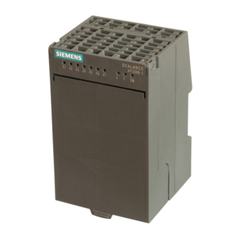
Page 58: Scalance X206-1
The SCALANCE X206-1 has six RJ-45 jacks and a BFOC port for the connection of end devices or other network segments. Note The BFOC socket (Bayonet Fiber Optic Connector) corresponds to the ST socket. Figure 3-15 SCALANCE X206-1 SCALANCE X-200 Operating Instructions, 12/2011, A5E00349864-19... -
Page 59: Scalance X206-1 Tp Ports
TP cords or TP-XP cords with a maximum length of 10 m can be connected to the RJ-45 TP port. With the IE FC cables and IE FC RJ-45 plug 180, an overall cable length of a maximum of 100 m is permitted between two devices depending on the cable type. SCALANCE X-200 Operating Instructions, 12/2011, A5E00349864-19... - Page 60 Such a loop can lead to network overload and network failures. Auto polarity exchange If the pair of receiving cables are incorrectly connected (RD+ and RD- swapped over), the polarity is reversed automatically. SCALANCE X-200 Operating Instructions, 12/2011, A5E00349864-19...
-
Page 61: Scalance X206-1 Fo Ports
The outer diameter of the FO cable is 125 µm. Transmission range The maximum transmission range (segment length) is up to 5 km depending on the cable type. Connectors The cables are connected over BFOC sockets. SCALANCE X-200 Operating Instructions, 12/2011, A5E00349864-19... -
Page 62: Scalance Xf206-1
The SCALANCE XF206-1 has six RJ-45 jacks and a BFOC port for the connection of end devices or other network segments. Note The BFOC socket (Bayonet Fiber Optic Connector) corresponds to the ST socket. Figure 3-17 SCALANCE XF206-1 SCALANCE X-200 Operating Instructions, 12/2011, A5E00349864-19... -
Page 63: Scalance Xf206-1 Tp Ports
TP cords or TP-XP cords with a maximum length of 10 m can be connected to the RJ-45 TP port. With the IE FC cables and IE FC RJ-45 plug 180, an overall cable length of a maximum of 100 m is permitted between two devices depending on the cable type. SCALANCE X-200 Operating Instructions, 12/2011, A5E00349864-19... - Page 64 Such a loop can lead to network overload and network failures. Auto polarity exchange If the pair of receiving cables are incorrectly connected (RD+ and RD- swapped over), the polarity is reversed automatically. SCALANCE X-200 Operating Instructions, 12/2011, A5E00349864-19...
-
Page 65: Scalance Xf206-1 Fo Ports
The outer diameter of the FO cable is 125 µm. Transmission range The maximum transmission range (segment length) is up to 5 km depending on the cable type. Connectors The cables are connected over BFOC sockets. SCALANCE X-200 Operating Instructions, 12/2011, A5E00349864-19... -
Page 66: Scalance X212-2
The SCALANCE X212-2 has 12 RJ-45 jacks and two BFOC interfaces for connecting end devices or other network segments. Note The BFOC socket (Bayonet Fiber Optic Connector) corresponds to the ST socket Figure 3-19 SCALANCE X 212-2 SCALANCE X-200 Operating Instructions, 12/2011, A5E00349864-19... -
Page 67: Scalance X212-2 Tp Ports
TP cords or TP-XP cords with a maximum length of 10 m can be connected to the RJ-45 TP port. With the IE FC cables and IE FC RJ-45 plug 180, an overall cable length of up to 100 m is permitted between two devices depending on the cable type. SCALANCE X-200 Operating Instructions, 12/2011, A5E00349864-19... - Page 68 Such a loop can lead to network overload and network failures. Auto polarity exchange If the pair of receiving cables are incorrectly connected (RD+ and RD- swapped over), the polarity is reversed automatically. SCALANCE X-200 Operating Instructions, 12/2011, A5E00349864-19...
-
Page 69: Scalance X212-2 Fo Ports
The outer diameter of the FO cable is 125 µm. Transmission range The maximum transmission range (segment length) is up to 5 km depending on the cable type. Connectors The cables are connected over BFOC sockets. SCALANCE X-200 Operating Instructions, 12/2011, A5E00349864-19... -
Page 70: Scalance X204-2Ld
The SCALANCE X204-2LD has four RJ-45 jacks and two BFOC ports for the connection of end devices or other network segments. Note The BFOC socket (Bayonet Fiber Optic Connector) corresponds to the ST socket. Figure 3-21 SCALANCE X204-2LD SCALANCE X-200 Operating Instructions, 12/2011, A5E00349864-19... -
Page 71: Scalance X204-2Ld Tp Ports
TP cords or TP-XP cords with a maximum length of 10 m can be connected to the RJ-45 TP port. With the IE FC cables and IE FC RJ-45 plug 180, an overall cable length of a maximum of 100 m is permitted between two devices depending on the cable type. SCALANCE X-200 Operating Instructions, 12/2011, A5E00349864-19... - Page 72 Such a loop can lead to network overload and network failures. Auto polarity exchange If the pair of receiving cables are incorrectly connected (RD+ and RD- swapped over), the polarity is reversed automatically. SCALANCE X-200 Operating Instructions, 12/2011, A5E00349864-19...
-
Page 73: Scalance X204-2Ld Tp Ports
Single mode fiber-optic cables are used with a core of 9 µm; the light source is an LED. The outer diameter of the FOC is 125 µm. Transmission range The maximum transmission range (segment length) is 26 km. SCALANCE X-200 Operating Instructions, 12/2011, A5E00349864-19... - Page 74 SCALANCE X204-2 SCALANCE XF204-2 SCALANCE X202-2IRT SCALANCE X212-2 SCALANCE X-400 with module type MM491-2 OMC TP11 OSM ITP62 OSM ITP53 OSM TP62 is not permitted. SCALANCE X-200 Operating Instructions, 12/2011, A5E00349864-19...
-
Page 75: Scalance X206-1Ld
The SCALANCE X206-1LD has six RJ-45 jacks and a BFOC port for the connection of end devices or other network segments. Note The BFOC socket (Bayonet Fiber Optic Connector) corresponds to the ST socket. Figure 3-23 SCALANCE X206-1LD SCALANCE X-200 Operating Instructions, 12/2011, A5E00349864-19... -
Page 76: Scalance X206-1Ld Tp Ports
TP cords or TP-XP cords with a maximum length of 10 m can be connected to the RJ-45 TP port. With the IE FC cables and IE FC RJ-45 plug 180, an overall cable length of a maximum of 100 m is permitted between two devices depending on the cable type. SCALANCE X-200 Operating Instructions, 12/2011, A5E00349864-19... - Page 77 Such a loop can lead to network overload and network failures. Auto polarity exchange If the pair of receiving cables are incorrectly connected (RD+ and RD- swapped over), the polarity is reversed automatically. SCALANCE X-200 Operating Instructions, 12/2011, A5E00349864-19...
-
Page 78: Scalance X206-1Ld Fo Ports
Single mode fiber-optic cables are used with a core of 9 µm; the light source is an LED. The outer diameter of the FOC is 125 µm. Transmission range The maximum transmission range (segment length) is 26 km. SCALANCE X-200 Operating Instructions, 12/2011, A5E00349864-19... - Page 79 SCALANCE X204-2 SCALANCE XF204-2 SCALANCE X202-2IRT SCALANCE X212-2 SCALANCE X-400 with module type MM491-2 OMC TP11 OSM ITP62 OSM ITP53 OSM TP62 is not permitted. SCALANCE X-200 Operating Instructions, 12/2011, A5E00349864-19...
-
Page 80: Scalance X212-2Ld
The SCALANCE X212-2LD has twelve RJ-45 jacks and two BFOC ports for the connection of end devices or other network segments. Note The BFOC socket (Bayonet Fiber Optic Connector) corresponds to the ST socket. Figure 3-25 SCALANCE X 212-2LD SCALANCE X-200 Operating Instructions, 12/2011, A5E00349864-19... -
Page 81: Scalance X212-2Ld Tp Ports
TP cords or TP-XP cords with a maximum length of 10 m can be connected to the RJ-45 TP port. With the IE FC cables and IE FC RJ-45 plug 180, an overall cable length of up to 100 m is permitted between two devices depending on the cable type. SCALANCE X-200 Operating Instructions, 12/2011, A5E00349864-19... - Page 82 Such a loop can lead to network overload and network failures. Auto polarity exchange If the pair of receiving cables are incorrectly connected (RD+ and RD- swapped over), the polarity is reversed automatically. SCALANCE X-200 Operating Instructions, 12/2011, A5E00349864-19...
-
Page 83: Scalance X212-2Ld Fo Ports
Single mode fiber-optic cables are used with a core of 9 µm; the light source is an LED. The outer diameter of the FOC is 125 µm. Transmission range The maximum transmission range (segment length) is 26 km. SCALANCE X-200 Operating Instructions, 12/2011, A5E00349864-19... - Page 84 SCALANCE X204-2 SCALANCE XF204-2 SCALANCE X202-2IRT SCALANCE X212-2 SCALANCE X-400 with module type MM491-2 OMC TP11 OSM ITP62 OSM ITP53 OSM TP62 is not permitted. SCALANCE X-200 Operating Instructions, 12/2011, A5E00349864-19...
-
Page 85: Scalance X202-2Irt
The SCALANCE X202-2IRT has two RJ-45 jacks and two BFOC ports for the connection of end devices or other network segments. Note The BFOC socket (Bayonet Fiber Optic Connector) corresponds to the ST socket. Figure 3-27 SCALANCE X202-2IRT SCALANCE X-200 Operating Instructions, 12/2011, A5E00349864-19... -
Page 86: Scalance X202-2Irt Tp Ports
TP cords or TP-XP cords with a maximum length of 10 m can be connected to the RJ-45 TP port. With the IE FC cables and IE FC RJ-45 plug 180, an overall cable length of a maximum of 100 m is permitted between two devices depending on the cable type. SCALANCE X-200 Operating Instructions, 12/2011, A5E00349864-19... - Page 87 Such a loop can lead to network overload and network failures. Auto polarity exchange If the pair of receiving cables are incorrectly connected (RD+ and RD- swapped over), the polarity is reversed automatically. SCALANCE X-200 Operating Instructions, 12/2011, A5E00349864-19...
-
Page 88: Scalance X202-2Irt Fo Ports
The outer diameter of the FO cable is 125 µm. Transmission range The maximum transmission range (segment length) is up to 5 km depending on the cable type. Connectors The cables are connected over BFOC sockets. SCALANCE X-200 Operating Instructions, 12/2011, A5E00349864-19... -
Page 89: Scalance X204Irt
Product properties 3.18 SCALANCE X204IRT 3.18 SCALANCE X204IRT 3.18.1 SCALANCE X204IRT product characteristics Possible attachments The SCALANCE X204IRT has four RJ-45 jacks for connecting end devices or other network segments. Figure 3-29 SCALANCE X204IRT SCALANCE X-200 Operating Instructions, 12/2011, A5E00349864-19... -
Page 90: Scalance X204Irt Tp Ports
TP cords or TP-XP cords with a maximum length of 10 m can be connected to the RJ-45 TP port. With the IE FC cables and IE FC RJ-45 plug 180, an overall cable length of up to 100 m is permitted between two devices depending on the cable type. SCALANCE X-200 Operating Instructions, 12/2011, A5E00349864-19... - Page 91 Such a loop can lead to network overload and network failures. Auto polarity exchange If the pair of receiving cables are incorrectly connected (RD+ and RD- swapped over), the polarity is reversed automatically. SCALANCE X-200 Operating Instructions, 12/2011, A5E00349864-19...
-
Page 92: Scalance Xf204Irt
Product properties 3.19 SCALANCE XF204IRT 3.19 SCALANCE XF204IRT 3.19.1 SCALANCE XF204IRT product characteristics Possible attachments The SCALANCE XF204IRT has four RJ-45 jacks for connecting end devices or other network segments. Figure 3-31 SCALANCE XF204IRT SCALANCE X-200 Operating Instructions, 12/2011, A5E00349864-19... -
Page 93: Scalance Xf204Irt Tp Ports
TP cords or TP-XP cords with a maximum length of 10 m can be connected to the RJ-45 TP port. With the IE FC cables and IE FC RJ-45 plug 180, an overall cable length of up to 100 m is permitted between two devices depending on the cable type. SCALANCE X-200 Operating Instructions, 12/2011, A5E00349864-19... - Page 94 Such a loop can lead to network overload and network failures. Auto polarity exchange If the pair of receiving cables are incorrectly connected (RD+ and RD- swapped over), the polarity is reversed automatically. SCALANCE X-200 Operating Instructions, 12/2011, A5E00349864-19...
-
Page 95: Scalance X204 Irt Pro
The SCALANCE X204 IRT PRO has four RJ-45 push-pull interfaces (PROFINET-compliant in accordance with IEC 61076-3-117) with the high degree of protection IP65/67 for connection of end devices or further network segments. Figure 3-33 SCALANCE X204 IRT PRO SCALANCE X-200 Operating Instructions, 12/2011, A5E00349864-19... -
Page 96: Scalance X204 Irt Pro Tp Ports
TP cords or TP-XP cords with a maximum length of 10 m can be connected to the RJ-45 TP port. With the IE FC cables and IE RJ-45 Plug PRO 180, an overall cable length of up to 100 m is permitted between two devices depending on the cable type. SCALANCE X-200 Operating Instructions, 12/2011, A5E00349864-19... - Page 97 Such a loop can lead to network overload and network failures. Auto polarity exchange If the pair of receiving cables are incorrectly connected (RD+ and RD- swapped over), the polarity is reversed automatically. SCALANCE X-200 Operating Instructions, 12/2011, A5E00349864-19...
-
Page 98: Scalance X202-2P Irt Pro
SC RJ push-pull interfaces (PROFINET-compliant in accordance with IEC 61754-24-2) with the high degree of protection IP65/67 for the connection of the end devices or further network segments. Figure 3-35 SCALANCE X202-2P IRT PRO SCALANCE X-200 Operating Instructions, 12/2011, A5E00349864-19... -
Page 99: Scalance X202-2P Irt Pro Tp Ports
TP cords or TP-XP cords with a maximum length of 10 m can be connected to the RJ-45 TP port. With the IE FC cables and IE RJ-45 Plug PRO 180, an overall cable length of a maximum of 100 m is permitted between two devices depending on the cable type. SCALANCE X-200 Operating Instructions, 12/2011, A5E00349864-19... - Page 100 Such a loop can lead to network overload and network failures. Auto polarity exchange If the pair of receiving cables are incorrectly connected (RD+ and RD- swapped over), the polarity is reversed automatically. SCALANCE X-200 Operating Instructions, 12/2011, A5E00349864-19...
-
Page 101: Scalance X202-2P Irt Pro Fo Ports
Transmission range The minimum cable length is 1 m. The maximum transmission distance (segment length) is 50 m for POF and 100 m for PCF cables. Connectors The cables are connected over SC-RJ sockets. SCALANCE X-200 Operating Instructions, 12/2011, A5E00349864-19... -
Page 102: Scalance X201-3P Irt Pro
IEC61076-3-117) with the high degree of protection IP65/67, and three SC RJ push pull interfaces (PROFINET-compliant according to IEC61754-24-2) with the high degree of protection IP65/67 for connection of end devices or other network segments. Figure 3-37 SCALANCE X201-3P IRT PRO SCALANCE X-200 Operating Instructions, 12/2011, A5E00349864-19... -
Page 103: Scalance X201-3P Irt Pro Tp Interfaces
TP cords or TP-XP cords with a maximum length of 10 m can be connected to the RJ-45 TP port. With the IE FC cables and IE RJ45 Plug PRO 180, an overall cable length of a maximum of 100 m is permitted between two devices depending on the cable type. SCALANCE X-200 Operating Instructions, 12/2011, A5E00349864-19... - Page 104 Such a loop can lead to network overload and network failures. Auto polarity exchange If the pair of receiving cables are incorrectly connected (RD+ and RD- swapped over), the polarity is reversed automatically. SCALANCE X-200 Operating Instructions, 12/2011, A5E00349864-19...
-
Page 105: Scalance X201-3P Irt Pro Fo Interfaces
Transmission range The minimum cable length is 1 m. The maximum transmission distance (segment length) is 50 m for POF and 100 m for PCF cables. Connectors The cables are connected over SC-RJ sockets. SCALANCE X-200 Operating Instructions, 12/2011, A5E00349864-19... -
Page 106: Scalance X202-2P Irt
3.23.1 SCALANCE X202-2P IRT product characteristics Possible attachments The SCALANCE X202-2P IRT has two RJ-45 jacks and two SC RJ interfaces for connecting end devices or other network segments. Figure 3-39 SCALANCE X202-2P IRT SCALANCE X-200 Operating Instructions, 12/2011, A5E00349864-19... -
Page 107: Scalance X202-2P Irt Tp Ports
TP cords or TP-XP cords with a maximum length of 10 m can be connected to the RJ-45 TP port. With the IE FC cables and IE FC RJ-45 plug 180, an overall cable length of a maximum of 100 m is permitted between two devices depending on the cable type. SCALANCE X-200 Operating Instructions, 12/2011, A5E00349864-19... - Page 108 Such a loop can lead to network overload and network failures. Auto polarity exchange If the pair of receiving cables are incorrectly connected (RD+ and RD- swapped over), the polarity is reversed automatically. SCALANCE X-200 Operating Instructions, 12/2011, A5E00349864-19...
-
Page 109: Scalance X202-2P Irt Fo Ports
Transmission range The minimum cable length is 1 m. The maximum transmission distance (segment length) is 50 m for POF and 100 m for PCF cables. Connectors The cables are connected over SC-RJ sockets. SCALANCE X-200 Operating Instructions, 12/2011, A5E00349864-19... -
Page 110: Scalance X201-3P Irt
3.24.1 SCALANCE X201-3P IRT product characteristics Possible attachments The SCALANCE X201-3P IRT has an RJ-45 jack and three SC RJ interfaces for connecting end devices or other network segments. Figure 3-41 SCALANCE X201-3P IRT SCALANCE X-200 Operating Instructions, 12/2011, A5E00349864-19... -
Page 111: Scalance X201-3P Irt Tp Ports
TP cords or TP-XP cords with a maximum length of 10 m can be connected to the RJ-45 TP port. With the IE FC cables and IE FC RJ-45 plug 180, an overall cable length of a maximum of 100 m is permitted between two devices depending on the cable type. SCALANCE X-200 Operating Instructions, 12/2011, A5E00349864-19... - Page 112 Such a loop can lead to network overload and network failures. Auto polarity exchange If the pair of receiving cables are incorrectly connected (RD+ and RD- swapped over), the polarity is reversed automatically. SCALANCE X-200 Operating Instructions, 12/2011, A5E00349864-19...
-
Page 113: Scalance X201-3P Irt Fo Ports
Transmission range The minimum cable length is 1 m. The maximum transmission distance (segment length) is 50 m for POF and 100 m for PCF cables. Connectors The cables are connected over SC-RJ sockets. SCALANCE X-200 Operating Instructions, 12/2011, A5E00349864-19... -
Page 114: Scalance X200-4P Irt
3.25 SCALANCE X200-4P IRT 3.25 SCALANCE X200-4P IRT 3.25.1 SCALANCE X200-4P IRT product characteristics Possible attachments The SCALANCE X200-4P IRT has four SC RJ interfaces for connecting end devices or other network segments. Figure 3-43 SCALANCEX200 4PIRT SCALANCE X-200 Operating Instructions, 12/2011, A5E00349864-19... -
Page 115: Scalance X200-4P Irt Fo Ports
Transmission range The minimum cable length is 1 m. The maximum transmission distance (segment length) is 50 m for POF and 100 m for PCF cables. Connectors The cables are connected over SC-RJ sockets. SCALANCE X-200 Operating Instructions, 12/2011, A5E00349864-19... -
Page 116: C-Plug (Configuration Plug)
Device combinations between which the C-PLUG can be exchanged: Device type C-PLUG created by device with Compatible with device with SCALANCE order number order number X208 6GK5208-0BA00-2AA3 6GK5208-0BA10-2AA3 X204-2 6GK5204-2BB00-2AA3 6GK5204-2BB10-2AA3 X206-1 6GK5206-1BB00-2AA3 6GK5206-1BB10-2AA3 X204-1LD 6GK5204-2BC00-2AA3 6GK5204-2BC10-2AA3 X206-1LD 6GK5206-1BC00-2AA3 6GK5206-1BC10-2AA3 SCALANCE X-200 Operating Instructions, 12/2011, A5E00349864-19... - Page 117 The slot for the C-PLUG is located as follows: ● On the IE Switch X-200 on the back of the device ● On the IE Switch XF-200 on the left hand side of the device SCALANCE X-200 Operating Instructions, 12/2011, A5E00349864-19...
- Page 118 Web Based Management and in the Command Line Interface. In this case, you will need to set the device to operation without C-PLUG. For further information, refer to the section "System C-PLUG WBM menu". Figure 3-44 Removing the C-PLUG from the receptacle SCALANCE X-200 Operating Instructions, 12/2011, A5E00349864-19...
-
Page 119: Button
On the SCALANCE X204 IRT PRO, SCALANCE X202-2P IRT PRO and SCALANCE X201- 3P IRT PRO, the button is beneath the C-PLUG cover on the rear of the device. On the SCALANCE XF-200, the button is below the front panel. SCALANCE X-200 Operating Instructions, 12/2011, A5E00349864-19... -
Page 120: Displays
1, 3, 4, 5, 6, 7, 8 X202-2P IRT 1, 2, 3, 4, 5, 6, 7, 8 X201-3P IRT 1, 2, 3, 4, 5, 6, 7, 8 X200-4P IRT 1, 2, 3, 4, 5, 6, 7, 8 SCALANCE X-200 Operating Instructions, 12/2011, A5E00349864-19... -
Page 121: Power Display
9. An internal fault was detected. Inform the maintenance personnel and, if necessary, send the device in for repair. 10. A loop was detected by the loop detection. 11. No fault detected by the IE Switch X-200. 3.28.2 Power display SCALANCE X-200 Operating Instructions, 12/2011, A5E00349864-19... - Page 122 3. Power supply L1 and L2 not connected or <14 V. 4. Power supplies L1 and L2 are not connected. Note SCALANCE X204 IRT PRO and SCALANCE X202-2P IRT PRO have no redundant power supply. SCALANCE X-200 Operating Instructions, 12/2011, A5E00349864-19...
-
Page 123: Port Status Indicator (Green/Yellow Leds)
The button was pressed for longer than 15 seconds to reset the configuration. 6. PROFINET IO operation was started with the PN IO controller, the attempt to change the fault mask with the button was rejected by all the port LEDs flashing once. SCALANCE X-200 Operating Instructions, 12/2011, A5E00349864-19... -
Page 124: Redundancy Manager Indicator (Green Led)
It changes its color depending on the function (redundancy function -> green, standby function -> yellow). In Web Based Management, the LED is labeled differently depending on the function (redundancy function, basic status -> label RM, standby function -> label SB). SCALANCE X-200 Operating Instructions, 12/2011, A5E00349864-19... -
Page 125: Standby Functions (Yellow Led)
X201-3P IRT PRO X202-2P IRT X201-3P IRT X200-4P IRT 1. Standby function is enabled (IE Switch X-200 is in standby active mode). 2. Standby function is enabled (IE Switch X-200 is in standby passive mode). SCALANCE X-200 Operating Instructions, 12/2011, A5E00349864-19... -
Page 126: Foc Diagnostic Display (Yellow Led)
(redundancy function, basic status -> label RM, standby function -> label SB). 3.28.6 FOC diagnostic display (yellow LED) Note Only the following devices have a fiber-optic diagnostics display X202-2P IRT PRO X201-3P IRT PRO X202-2P IRT X201-3P IRT X200-4P IRT SCALANCE X-200 Operating Instructions, 12/2011, A5E00349864-19... -
Page 127: Led Display During Startup
3. Port LEDs go off, the red error LED is lit for approx. 20 seconds. 4. After the port LEDs go off, the correct link status is displayed after approx. 2 seconds. 5. The IE Switch X-200 is now ready for operation. SCALANCE X-200 Operating Instructions, 12/2011, A5E00349864-19... - Page 128 Product properties 3.28 Displays SCALANCE X-200 Operating Instructions, 12/2011, A5E00349864-19...
-
Page 129: Installation
Unless stated otherwise, the mounting options listed below apply to all X-200 IE switches. Note Provide suitable shade to protect the IE Switch X-200 against direct sunlight. This avoids unwanted warming of the IE Switch X-200 and prevents premature aging of the device and cabling. SCALANCE X-200 Operating Instructions, 12/2011, A5E00349864-19... - Page 130 When installing the IE switch, select a location where only qualified service personnel or trained users have access to it. Operation of the SCALANCE X-200 at ambient temperatures of 60 °C - 70°C is only permitted under these conditions. WARNING If temperatures in excess of 70 °C occur on cables or at cable feed-in points, or the...
-
Page 131: Installation On A Din Rail
2. Use a screwdriver to release the lower DIN rail catch of the device and pull the lower part of the device away from the rail. Figure 4-2 IE Switch X-200 removing from a DIN rail (35 mm) SCALANCE X-200 Operating Instructions, 12/2011, A5E00349864-19... -
Page 132: Installation On A Standard Rail
Removing an IE Switch X-200 from a SIMATIC S7-300 standard rail 1. First disconnect all connected cables. 2. Loosen the screws on the underside of the S7 standard rail and lift the IE Switch X-200 away from the rail. SCALANCE X-200 Operating Instructions, 12/2011, A5E00349864-19... -
Page 133: Wall Mounting
For more exact dimensions, please refer to the section "Dimension drawings". Note The wall mounting must be capable of supporting at least four times the weight of the IE Switch X-200 (see "Technical specifications"). SCALANCE X-200 Operating Instructions, 12/2011, A5E00349864-19... - Page 134 Installation 4.4 Wall mounting SCALANCE X-200 Operating Instructions, 12/2011, A5E00349864-19...
-
Page 135: Connection
6 A are conducted via the connector, metal connectors must be used. Note In areas subject to the National Electric Code (NEC), the Canadian Electric Code (CEC) and the EU directive 94/9 (ATEX), metal connectors must be used. SCALANCE X-200 Operating Instructions, 12/2011, A5E00349864-19... - Page 136 (see the table "Operation under marginal conditions"), the device may only be used when installed as shown in the following figure: "Mounting position for operation under marginal conditions". If no power is looped through, any installation position is permitted. SCALANCE X-200 Operating Instructions, 12/2011, A5E00349864-19...
- Page 137 Table 5- 1 Operation under marginal conditions Environment Max Power 1 (L1+, N1) Max Power 2 (L2+, N2) +40℃ 16 A 16 A +50℃ 12 A 12 A +60℃ SCALANCE X204 IRT PRO only +70°C SCALANCE X-200 Operating Instructions, 12/2011, A5E00349864-19...
- Page 138 Because the SCALANCE X204 IRT PRO, the SCALANCE X202-2P IRT PRO and the SCALANCE X201-3P IRT PRO do not have a redundant power supply, the power supply must be connected to L1 and N1. SCALANCE X-200 Operating Instructions, 12/2011, A5E00349864-19...
- Page 139 A suitable device is, for example, the Dehn Blitzductor VT AD 24 V type no. 918 402 or comparable protective element. Manufacturer: DEHN+SÖHNE GmbH+Co.KG, Hans-Dehn-Str.1, Postfach 1640, D-92306 Neumarkt, Germany. SCALANCE X-200 Operating Instructions, 12/2011, A5E00349864-19...
-
Page 140: Signaling Contact
SCALANCE X204 IRT PRO, SCALANCE X202-2P IRT PRO and SCALANCE X201-3P IRT PRO have no redundant power supply ● Incompatible C-PLUG was inserted. The connection or disconnection of a communication node on an unmonitored port does not lead to an error message. SCALANCE X-200 Operating Instructions, 12/2011, A5E00349864-19... - Page 141 The signaling contact remains activated until the error/fault is eliminated or until the current status is applied as the new desired status using the button. When the IE Switch X-200 is turned off, the signaling contact is always activated (open). SCALANCE X-200 Operating Instructions, 12/2011, A5E00349864-19...
-
Page 142: Grounding
If an IE Switch X-200 is mounted on a non-conducting base, a grounding cable must be installed. The grounding cable is not supplied with the device. Connect the paint-free surface of the device to the nearest grounding point using the grounding cable. SCALANCE X-200 Operating Instructions, 12/2011, A5E00349864-19... -
Page 143: Fitting The Ie Fc Rj-45 Plug 180
TP port of the IE Switch X-200 guarantee a robust node connection suitable for industrial conditions providing tensile and bending strain relief for the twisted pair socket. SCALANCE X-200 Operating Instructions, 12/2011, A5E00349864-19... - Page 144 If there is not enough space to release the lock with your hand, you can also use a 2.5 mm screwdriver. You can then remove the IE FC RJ-45 Plug 180 from the twisted pair socket. Figure 5-5 Releasing the RJ-45 Plug with a screwdriver SCALANCE X-200 Operating Instructions, 12/2011, A5E00349864-19...
-
Page 145: Fitting The Ie Rj 45 Plug Pro And Ie Sc Rj Plug Pro
1. Remove IE RJ 45 Plug Pro or IE SC RJ Plug Pro from the socket of the IE Switches X- 200. Figure 5-8 Removing IE RJ 45 Plug Pro or IE SC RJ Plug Pro SCALANCE X-200 Operating Instructions, 12/2011, A5E00349864-19... - Page 146 Connection 5.5 Fitting the IE RJ 45 Plug Pro and IE SC RJ Plug Pro SCALANCE X-200 Operating Instructions, 12/2011, A5E00349864-19...
-
Page 147: Configuration / Diagnostics Using Remote Mechanisms
IE switch must not be disabled. 6.1.2 Configuration with the Primary Setup Tool 6.1.2.1 Configuration with the Primary Setup Tool Primary Setup Tool (PST) The Primary Setup Tool is on the CD supplied with the device. SCALANCE X-200 Operating Instructions, 12/2011, A5E00349864-19... -
Page 148: Installing The Primary Setup Tool
4. The dialog box for selecting the installation folder appears. Click on the Next button if you want to accept the default C:\Program Files\Siemens\Primary Setup Tool\ . If you want to specify a different folder, you can open a dialog box for selecting a folder by clicking the Browse button. -
Page 149: The Dlc Protocol
3. Open the Properties dialog using the context-sensitive menu (right mouse button). The General tab lists all the protocols and services. The DLC protocol should be listed and selected: Figure 6-1 Properties of local area connection SCALANCE X-200 Operating Instructions, 12/2011, A5E00349864-19... -
Page 150: Installing The Dlc Protocol
While the Primary Setup Tool browses the network, the Browse Network dialog is displayed with a progress bar. On completion of the search, the Primary Setup Tool displays a list with all the devices it has found in the left-hand pane. SCALANCE X-200 Operating Instructions, 12/2011, A5E00349864-19... -
Page 151: Configuring A Module
The information on the router is necessary if the computer with which you are creating the configuration is not in the same subnet as the device you are configuring. SCALANCE X-200 Operating Instructions, 12/2011, A5E00349864-19... - Page 152 2. Start the download with one of the steps outlined below: – Select the Module > Download menu command. – Click on the second button from the left in the toolbar (S7 modules with yellow arrow). Figure 6-3 Dialog for downloading a module SCALANCE X-200 Operating Instructions, 12/2011, A5E00349864-19...
- Page 153 After selecting th is menu, a dialog appears with which you can start and finish signaling. The activity of the LEDs indicates which device is assigned to a particular list entry in the program window. SCALANCE X-200 Operating Instructions, 12/2011, A5E00349864-19...
-
Page 154: Configuration With Dhcp
IP address again, it is normally assigned a different address. It is, however, possible to configure the DHCP server so that it makes a fixed address assignment. RFC - Request for Comments The following RFC can be downloaded from the Internet: RFC 2131 - Dynamic Host Configuration Protocol SCALANCE X-200 Operating Instructions, 12/2011, A5E00349864-19... -
Page 155: Updating The Firmware With The Boot Loader
● Send a firmware file to the IE Switch X-200 using FTP. You can use any FTP client to do this. ● Use the following connection settings for FTP access: – User name: siemens – Password: siemens – Transmission mode: Binary ●... -
Page 156: Configuration Using Web Based Management (Wbm) And Command Line Interface (Cli)
Web Based Management before turning off the device. You can then be certain that all the configuration changes have been saved. Note To use SNMP Management, RMON, and traps, you require a network management station. This does not ship with IE switches. SCALANCE X-200 Operating Instructions, 12/2011, A5E00349864-19... -
Page 157: Principle Of Web Based Management
Below the text , the check box must be selected. ● Web Based Management is HTTP- or HTTPS-based, so you must also enable access to port 80 or 443 if you have a firewall installed. SCALANCE X-200 Operating Instructions, 12/2011, A5E00349864-19... - Page 158 Note For security reasons, make sure that you change the original factory-set passwords. Resetting the device also resets the passwords to the factory settings. 4. Click the "Log On" button to start the logon. SCALANCE X-200 Operating Instructions, 12/2011, A5E00349864-19...
-
Page 159: Led Simulation
TELNET connection. ● Support This link initiates an Internet connection that takes you directly to the support pages of SIEMENS AG. This is only possible when the PC supports an Internet connection. ● Log out Closes the browser window. - Page 160 If you click on this button, configuration data you have set is stored on the device. NOTICE It is only possible to change the configuration if you log on as "admin". Note A blue text is a link that can be clicked. SCALANCE X-200 Operating Instructions, 12/2011, A5E00349864-19...
-
Page 161: Command Line Interface (Cli)
Before you can enter a command in the Command Line Interface, you must first open the required menu or submenu. This section lists the commands of each menu in a separate table. The table lists only the commands themselves. SCALANCE X-200 Operating Instructions, 12/2011, A5E00349864-19... - Page 162 Displays the commands available in the menu. Administrator and User exit Closes the CLI session. Administrator and User restart Restarts the IE switch Administrator only About Displays information on the current menu item. Administrator and User SCALANCE X-200 Operating Instructions, 12/2011, A5E00349864-19...
-
Page 163: Wbm Menus
Management menus - the Start menu The Start dialog The following start screen appears after you enter the login and password in WBM. Select the required function from the menu on the left-hand side. Figure 6-7 "Start Menu" dialog SCALANCE X-200 Operating Instructions, 12/2011, A5E00349864-19... -
Page 164: The "System" Wbm Menu
Enter the name of a contact person responsible for managing the device in this box. System Location In this box, you enter a location for the device, for example a room number. System Name Enter a description of the device in this box. SCALANCE X-200 Operating Instructions, 12/2011, A5E00349864-19... - Page 165 [Device Name] Sets the "PNIO Device Name" variable. Administrator only name [sysName] Sets the "sysName" variable. Administrator only contact [sysContact] Sets the "sysContact" variable. Administrator only location [sysLocation] Sets the "sysLocation" variable. Administrator only SCALANCE X-200 Operating Instructions, 12/2011, A5E00349864-19...
-
Page 166: System C-Plug" Wbm Menu
No C-PLUG or C-PLUG inserted but invalid or incompatible content. This status is also displayed if the C-PLUG was formatted during operation. ● NOT ACCEPTED, HEADER CRC ERROR A C-PLUG with bad content is inserted. SCALANCE X-200 Operating Instructions, 12/2011, A5E00349864-19... - Page 167 If you remove the C-PLUG later, the configuration stored internally on the basic device becomes valid again. This restores the configuration status prior to inserting the C-PLUG. Modify C-PLUG, Modify button If you are logged on as administrator, you can make settings here. SCALANCE X-200 Operating Instructions, 12/2011, A5E00349864-19...
- Page 168 Command Line Interface. By entering the useplug D command, you can change the device to operate in the mode without C-PLUG. clear Erases the data on the C-PLUG. Administrator only. SCALANCE X-200 Operating Instructions, 12/2011, A5E00349864-19...
-
Page 169: The "System I&M" Wbm Menu
Here, you can see the individual parameters for Identification & Maintenance. I&M 1 Function tag Here, you can enter the function tag (plant designation). Location tag Here, you can enter the location tag (location identifier). SCALANCE X-200 Operating Instructions, 12/2011, A5E00349864-19... -
Page 170: The "System Restart & Defaults" Wbm Menu
The "System Restart & Defaults" WBM menu System Restart & Defaults In this screen, there is a button with which you can restart the device and various options for resetting to the device defaults. Figure 6-11 "Restart and Defaults" dialog SCALANCE X-200 Operating Instructions, 12/2011, A5E00349864-19... - Page 171 System Restart & Defaults - CLI\SYSTEM\RESTARTS> Command Description Comment memreset Restores the factory defaults. Administrator only. The protected settings are retained. defaults Restores the factory defaults. Administrator only. The protected settings are also reset. SCALANCE X-200 Operating Instructions, 12/2011, A5E00349864-19...
-
Page 172: The "System Save & Load Http" Wbm Menu
Switch X-200 or where you want to store the current configuration information. Note When a configuration file is downloaded, the device type is not checked. Event Log File By clicking "Save", you can save the event table (event log file) on the local computer. SCALANCE X-200 Operating Instructions, 12/2011, A5E00349864-19... - Page 173 The private key and the certificate for SSL are required to allow the user to communicate via a secure connection with the Web server on the IE Switch X-200. The files must be available in PEM format. SCALANCE X-200 Operating Instructions, 12/2011, A5E00349864-19...
-
Page 174: The "System Save & Load Tftp" Wbm Menu
Name and possibly also folder path of the configuration file (maximum 32 characters) that you want to load on the IE Switch X-200 or where you want to store the current configuration information. Note When a configuration file is downloaded, the device type is not checked. SCALANCE X-200 Operating Instructions, 12/2011, A5E00349864-19... - Page 175 The private key and the certificate for SSL are required to allow the user to communicate via a secure connection with the Web server on the IE Switch X-200. The files must be available in PEM format. SCALANCE X-200 Operating Instructions, 12/2011, A5E00349864-19...
- Page 176 Loads the private SSL key from Administrator only. a file. ctname Specifies the name of the file Administrator only. (maximum 255 characters) that contains the SSL certificate. ctload Loads the SSL certificate from a Administrator only. file. SCALANCE X-200 Operating Instructions, 12/2011, A5E00349864-19...
-
Page 177: The "System Version Numbers" Wbm Menu
Hardware Revision Displays the version of the device. MAC Address Displays the MAC address of the device. MLFB Number Displays the order number of the device. Serial number Displays the serial number of the device. SCALANCE X-200 Operating Instructions, 12/2011, A5E00349864-19... - Page 178 System Information - CLI\> Command Description Comment info Displays the MAC address, MLFB and serial number Table 6- 8 System Configuration - CLI\SYSTEM> Command Description Comment versions Shows versions of firmware, hardware and boot software. SCALANCE X-200 Operating Instructions, 12/2011, A5E00349864-19...
-
Page 179: The "System Passwords" Wbm Menu
For the user: user. Figure 6-15 "System Passwords" dialog Table 6- 9 System Passwords - CLI\SYSTEM> Command Description Comment password <admin ¦ user> Sets a new password for the Administrator only. <password> user or administrator. SCALANCE X-200 Operating Instructions, 12/2011, A5E00349864-19... -
Page 180: The "System Select/Set Button" Wbm Menu
Here, you can specify whether or not it is possible to set the fault mask with a button. 6.3.5.11 The "System Event Log" WBM menu System Event Log Table This dialog shows which events occurred and when. You specify the events that are to be logged in the "Agent/Event Config" dialog. SCALANCE X-200 Operating Instructions, 12/2011, A5E00349864-19... - Page 181 Indicates or erases expired events in Administrator only. memory. eventmax [Max count] Specifies the maximum number of events Administrator only. in the log table. A maximum of 10 to 400 entries can be set. SCALANCE X-200 Operating Instructions, 12/2011, A5E00349864-19...
-
Page 182: The "X200" Wbm Menu
This page provides information on operating states such as power supply and fault status. Figure 6-18 "Status" dialog Power This displays how the power is supplied. Fault Status Indicates whether faults are pending and if so which. SCALANCE X-200 Operating Instructions, 12/2011, A5E00349864-19... -
Page 183: The "X200 Fault Mask" Wbm Menu
Here, you can enable/disable monitoring of the redundant power supply. Note The following devices do not have a redundant power supply: SCALANCE X204 IRT PRO SCALANCE X202-2P IRT PRO SCALANCE X201-3P IRT PRO SCALANCE X-200 Operating Instructions, 12/2011, A5E00349864-19... - Page 184 Specifies a port mask for the ports for which the Administrator only. monitoring of a link up event is enabled. others <P> <E¦D> Specifies the fault mask for: Administrator only. P - power mask SCALANCE X-200 Operating Instructions, 12/2011, A5E00349864-19...
-
Page 185: The "X200 Ring" Wbm Menu
As default, a mode for automatic ring configuration is enabled. This causes cyclic frame communication at a low data rate. If it is not required, disable this redundancy function to avoid unnecessary network load. SCALANCE X-200 Operating Instructions, 12/2011, A5E00349864-19... - Page 186 "MRP Client", this device automatically adopts the role of "MRP Manager". Select "MRP Client" mode if you want to operate the device along with components that do not originate from Siemens in the ring. SCALANCE X-200 Operating Instructions, 12/2011, A5E00349864-19...
- Page 187 Number of state changes (relevant only when the redundancy role "HSR Manager" or "MRP Manager" was adopted) This shows how often the redundancy manager switched to a different path due to an interruption in the ring since the device was turned on. SCALANCE X-200 Operating Instructions, 12/2011, A5E00349864-19...
- Page 188 – With SCALANCE X212-2 and X212-2LD, ports 9 to 14 can be selected as MRP ring ports. The default ring ports are adapted automatically if you select MRP. Make sure that the ring ports are set correctly. SCALANCE X-200 Operating Instructions, 12/2011, A5E00349864-19...
- Page 189 [n-m | n-m] Specifies the two ring ports in the range n-m. Administrator only. clear Resets all redundancy counters to the Administrator only. original setting. redund [E ¦ D] Enables / disables ring redundancy. Administrator only. SCALANCE X-200 Operating Instructions, 12/2011, A5E00349864-19...
-
Page 190: The "X200 Standby" Wbm Menu
Figure 6-21 X202-2IRT Standby Manager dialog Enable Standby manager This function is enabled and disabled here. Standby port The coupling to the second ring is carried out over the selected port. SCALANCE X-200 Operating Instructions, 12/2011, A5E00349864-19... - Page 191 Specifies the name of the standby connection. Administrator only clear Resets all counters to the original setting. Administrator only standby [E|D] Enables/disables the standby manager. Administrator only force [E|D] Enables/disables the device as standby master. Administrator only SCALANCE X-200 Operating Instructions, 12/2011, A5E00349864-19...
-
Page 192: The "Agent" Wbm Menu
IE Switch X-200 obtains its IP address dynamically or has a fixed address. You can also enable options for accessing the IE Switch X-200 such as TELNET. Figure 6-22 "Agent Configuration" dialog Note When supplied, SSH and TELNET are activated. When supplied, DHCP (identification via MAC address) is enabled. SCALANCE X-200 Operating Instructions, 12/2011, A5E00349864-19... - Page 193 IP address 192.168.1.1. wbmtime [minutes] Displays or specifies the time limit after which a Administrator only. WBM connection is reset. A maximum value of 999 minutes can be set. The value 0 disables the time limit. SCALANCE X-200 Operating Instructions, 12/2011, A5E00349864-19...
-
Page 194: The "Ping" Wbm Menu
Enter the IP address of the network device you want to ping to test whether it can be reached. Repeat Here, enter the number of data packets to be sent. Ping Click this button to start sending the data packets. Ping Output This box shows the output of the ping function. SCALANCE X-200 Operating Instructions, 12/2011, A5E00349864-19... -
Page 195: The "Agent Snmp Config" Wbm Menu
Here, you can decide whether only SNMPv3 or also SNMPv1/v2 can be used. SNMP Read Only Enables/disables write protection for SNMP variables. SNMP Community Strings Read Community String Displays the user name for read access to SNMP variables. SCALANCE X-200 Operating Instructions, 12/2011, A5E00349864-19... - Page 196 Enables / disables SNMPv1 read only mode. Administrator only. getcomm [string] Specifies the Read Community string. Administrator only. setcomm [string] Specifies the Write Community string. Administrator only. traps [E ¦ D] Enables / disables SNMPv1 traps. Administrator only. SCALANCE X-200 Operating Instructions, 12/2011, A5E00349864-19...
-
Page 197: The "Agent Snmp Trap Config" Wbm Menu
Here, you enter the addresses of the stations to which the IE Switch X-200 will send traps. Enable Trap Click on the check box next to the IP addresses to enable the sending of traps to the corresponding stations. SCALANCE X-200 Operating Instructions, 12/2011, A5E00349864-19... -
Page 198: The "Agent Snmp Config Groups" Wbm Menu
In this screen, you create or delete user groups for device access using SNMPv3. You can decide whether or not members of a group need to authenticate themselves, whether they communicate with encryption and whether they have read and write permissions. Figure 6-25 Agent SNMP Configuration Groups screen SCALANCE X-200 Operating Instructions, 12/2011, A5E00349864-19... - Page 199 <index> Deletes an SNMPv3 group. The Administrator only. index of the group to be deleted must be obtained with the "Info" command. clearall Deletes all the SNMPv3 groups Administrator only. that have been created. SCALANCE X-200 Operating Instructions, 12/2011, A5E00349864-19...
-
Page 200: Scalance X
Agent SNMP Configuration Group Table dialog Group Name Enter the name of the SNMPv3 group you want to create here. Security Level Here, you set the required security level for the group you are creating. SCALANCE X-200 Operating Instructions, 12/2011, A5E00349864-19... - Page 201 200 but nevertheless communicate without encryption. Auth/Priv The members of the group need to authenticate themselves and communicate via an encrypted SNMP connection. Access Here, you decide whether the members of the group have read and write permissions. SCALANCE X-200 Operating Instructions, 12/2011, A5E00349864-19...
-
Page 202: The "Agent Snmp Config Users" Wbm Menu
Agent SNMP Configuration Users - CLI\AGENT\SNMP\USER> Command Description Comment info Displays a list of all created SNMPv3 users. add <user> <group> [NONE | Adds a new SNMPv3 user to a Administrator only. MD5 | SHA] [Authpass] user group. [Privpass] SCALANCE X-200 Operating Instructions, 12/2011, A5E00349864-19... -
Page 203: The "Agent Snmp Config User Table" Wbm Menu
Agent SNMP Configuration User Table If you want to create a new SNMPv3 user, this dialog appears: Figure 6-28 Agent SNMP Configuration User Table dialog User Name Enter the name of the user you want to create here. SCALANCE X-200 Operating Instructions, 12/2011, A5E00349864-19... -
Page 204: The "Agent Event Config" Wbm Menu
● The IE Switch X-200 sends an e-mail. ● The IE Switch X-200 triggers an SNMP trap. ● The IE Switch X-200IRT saves the relevant event in the event table. Figure 6-29 "Agent Event Configuration" dialog SCALANCE X-200 Operating Instructions, 12/2011, A5E00349864-19... - Page 205 Select this check box if you want to close the signaling contact. Note The setting of the "Close Signaling Contact" check box is only effective if the "aligned" setting was selected in the "Signaling Contact Control" drop-down list. SCALANCE X-200 Operating Instructions, 12/2011, A5E00349864-19...
- Page 206 E-mail Trap Entry in the log table Example: If you only want to send an E-mail when there is a Link Change, enter the following command: setec LC E D D SCALANCE X-200 Operating Instructions, 12/2011, A5E00349864-19...
-
Page 207: The "Agent E-Mail Config" Wbm Menu
Here, you enter the E-mail address to which the IE Switch X-200 sends an E-mail if a fault occurs. SMTP Server IP Address Here, you enter the IP address of the SMTP server over which the E-mail is sent. SCALANCE X-200 Operating Instructions, 12/2011, A5E00349864-19... - Page 208 Specifies the address to which Administrator only. an IE switch sends an E-mail. This address can be up to a maximum of 50 characters long. testmail <test E-mail comment> Sends an E-mail for testing. Administrator only. SCALANCE X-200 Operating Instructions, 12/2011, A5E00349864-19...
-
Page 209: The "Agent Time Config" Wbm Menu
Time zone offset, Time server, Init poll interval, Poll interval. ● SNTP Listen In this mode, you can also select an offset to the time received from the server. Other settings are not possible. SCALANCE X-200 Operating Instructions, 12/2011, A5E00349864-19... - Page 210 [P ¦ L ¦ S ¦ M] Specifies how the time is set: Administrator only. - P SNTP poll - L SNTP listen - S Siemens - M manual. settime [time] Sets the time manually Administrator only. (DD MMM HH:MM:SS YYYY).
-
Page 211: The "Switch" Wbm Menu
The "Switch" WBM menu Port Mirroring Note for all SCALANCE X-200 IRT Disable the function "Port Mirroring" if you want to operate the device in IRT mode. IRT mode is not possible when the mirroring function is enabled. With this dialog, you can enable or disable port mirroring; in other words, mirroring the data traffic from the mirror port to the monitor port. - Page 212 [Port] Specifies the port for the protocol monitor. Administrator only. mirroring [E|D] Enables / disables mirroring. Administrator only. plisten [E|D] Enables/disables passive listening Administrator only. oversize [E|D] Enables/disables the oversize mode function Administrator only. SCALANCE X-200 Operating Instructions, 12/2011, A5E00349864-19...
-
Page 213: The "Switch Ports" Wbm Menu
The following port types are available with the IE Switch X-200 modules: TP 10 TX TP 100 TX FO 100 FX Mode Shows transmission rate (10 or 100 Mbps) and the transmission mode (full duplex (FD) or half duplex (HD)). SCALANCE X-200 Operating Instructions, 12/2011, A5E00349864-19... - Page 214 Displays the port status. Administrator only. Table 6- 25 Switch Ports Status - CLI\SWITCH\SETPORT> Command Description Comment info Displays the current port settings. enable <port> [D ¦ E] Enables / disables the specified port. Administrator only. SCALANCE X-200 Operating Instructions, 12/2011, A5E00349864-19...
- Page 215 <port> [H¦F¦A] Specifies the port duplexity: Administrator only. H - half F - full A - autonegotiation If autonegotiation is set, the setting applies for speed and duplicity. SCALANCE X-200 Operating Instructions, 12/2011, A5E00349864-19...
-
Page 216: The "Switch Port Diags" Wbm Menu
The port to be tested is specified here. Run Test This button activates the test. Pair Displays the pair of wires in the cable. Pairs 4-5 and 7-8 are not used. Status Displays the status of the cable. SCALANCE X-200 Operating Instructions, 12/2011, A5E00349864-19... -
Page 217: The "Switch Fdb" Wbm Menu
Switch Forwarding Database The forwarding database displays which MAC addresses are currently reachable in the network via which port. The FDB is refreshed each time the aging time elapses. Figure 6-35 Switch Forwarding Database dialog SCALANCE X-200 Operating Instructions, 12/2011, A5E00349864-19... - Page 218 SCALANCE X-200IRT IE switches can learn up to 4000 Ethernet addresses, the other SCALANCE X-200 IE switches up to 8000 Ethernet addresses. The entry of a learned Ethernet address in the address table is made by the storage system which may reduce the actual number of addresses that can be learned.
-
Page 219: The "Switch Arp Table" Wbm Menu
Displays the ARP table. 6.3.5.32 The "Switch LLDP" WBM menu Configuring frames of the Link Layer Discovery Protocol This dialog allows you to configure the handling of frames of the Link Layer Discovery Protocol (LLDP) per port. SCALANCE X-200 Operating Instructions, 12/2011, A5E00349864-19... - Page 220 With all other X-200 IE switches, MAC addresses are used as the sender address for LLDP frames that are both device and port-specific. The MAC address for a specific port is formed by adding the index of this port to the MAC address of the IE Switch X-200. SCALANCE X-200 Operating Instructions, 12/2011, A5E00349864-19...
- Page 221 Port sends and receives LLDP frames. LLDP frames are neither sent nor received. (not with X-200IRT IE switches) LLDP frames are sent but not received. LLDP frames are received but not sent. (not with X-200IRT IE switches) SCALANCE X-200 Operating Instructions, 12/2011, A5E00349864-19...
-
Page 222: The "Switch Dcp" Wbm Menu
To allow the logical structuring of networks, the sending of DCP frames can be enabled or disabled port-oriented on an IE Switch X-200. Note The sending of DCP frames can be disabled in STEP 7 using the "End of detection of accessible nodes" function. SCALANCE X-200 Operating Instructions, 12/2011, A5E00349864-19... - Page 223 If DCP is turned off, it may not be possible to configure all switches with the PST tool. The following settings can be made for the displayed ports: Symbol Meaning Port sends and receives DCP frames DCP frames are received but not sent SCALANCE X-200 Operating Instructions, 12/2011, A5E00349864-19...
-
Page 224: The "Switch Pof" Wbm Menu
This screen displays the diagnostic data for interfaces with plastic FO cables. Figure 6-37 POF Management Here, you can see the currently available link power margin as a numerical value for each POF port. SCALANCE X-200 Operating Instructions, 12/2011, A5E00349864-19... - Page 225 The diagram itself is divided into two areas: White: There is an adequate link power margin for problem-free operation. When the IE Switch X- 200 is installed, the link power margin should be in this range. SCALANCE X-200 Operating Instructions, 12/2011, A5E00349864-19...
-
Page 226: The "Loop Detection Config" Wbm Menu
If the sent frames are received again at the same port, there is a "Remote Loop" involving other network components. Note Note that loop detection is only possible at ports that were not configured as ring ports. SCALANCE X-200 Operating Instructions, 12/2011, A5E00349864-19... - Page 227 Configuration / diagnostics using remote mechanisms 6.3 Configuration using Web Based Management (WBM) and Command Line Interface (CLI) SCALANCE X-200 Operating Instructions, 12/2011, A5E00349864-19...
- Page 228 ● "Local Loop Reaction" drop-down list Here, you can activate or deactivate a port if a local loop is detected. ● "State" display box Shows the status of the loop detection for the corresponding port. SCALANCE X-200 Operating Instructions, 12/2011, A5E00349864-19...
- Page 229 Specifies the reaction to a local loop. Administrator only. remote <port> Specifies the reaction to a remote loop. Administrator only. [N | D] reset <port> Reactivates the port if it was deactivated due to a detected Administrator only. loop. SCALANCE X-200 Operating Instructions, 12/2011, A5E00349864-19...
-
Page 230: The "Statistics" Wbm Menu
"Statistics Throughput" dialog Octets In Displays the number of received bytes. Octets Out Displays the number of sent bytes. Frames In Displays the number of received frames. Frames Out Displays the number of sent frames. SCALANCE X-200 Operating Instructions, 12/2011, A5E00349864-19... - Page 231 Displays information on the type of the sent and received frames. sizes Displays information on the length of the sent and received frames. errors Displays information on bad sent and received frames. SCALANCE X-200 Operating Instructions, 12/2011, A5E00349864-19...
-
Page 232: The "Statistics Packet Size" Wbm Menu
Displays the number of packets with a length of 128-255 bytes. 256-511 Displays the number of packets with a length of 256-511 bytes. 512-1023 Displays the number of packets with a length of 512-1023 bytes. SCALANCE X-200 Operating Instructions, 12/2011, A5E00349864-19... - Page 233 "Statistics Packet Size Graphic" dialog (graphic view) Syntax of the Command Line Interface Table 6- 33 Statistic Packet Size - CLI\INFORM> Command Description Comment sizes Shows statistical information broken down according to frame length. SCALANCE X-200 Operating Instructions, 12/2011, A5E00349864-19...
-
Page 234: The "Statistics Packet Type" Wbm Menu
"Statistics Packet Type" dialog Unicast Displays the number of packets to the unicast recipient address. Multicast Displays the number of packets to the multicast recipient address. Broadcast Displays the number of packets to the broadcast recipient address. SCALANCE X-200 Operating Instructions, 12/2011, A5E00349864-19... - Page 235 "Statistics Packet Type Graphic" dialog (graphic view) Syntax of the Command Line Interface Table 6- 34 Statistic Packet Type - CLI\INFORM> Command Description Comment types Shows statistical information broken down according to frame type. SCALANCE X-200 Operating Instructions, 12/2011, A5E00349864-19...
-
Page 236: The "Statistics Packet Error" Wbm Menu
The following errors can be detected: Packets with a valid length but bad checksum. Undersize Packets too short with valid checksum. Oversize Packets too long with valid checksum. Jabbers Packets too long without valid checksum. Collisions SCALANCE X-200 Operating Instructions, 12/2011, A5E00349864-19... - Page 237 If the frame involved is a frame with a length of 64 bytes, the counter for undersize errors is also incremented due to the shortening of the frame Syntax of the Command Line Interface Table 6- 35 Statistic Packet Error - CLI\INFORM> Command Description Comment errors Displays statistical information on received errors. SCALANCE X-200 Operating Instructions, 12/2011, A5E00349864-19...
-
Page 238: Snmp
Configuration and diagnostics over SNMP Configuration of an IE Switch X-200 over SNMP A network management station can configure and monitor a SCALANCE X-200 using SNMP (Simple Network Management Protocol). To allow this, a management agent is installed in the IE Switch X-200 with which the management station exchanges data using Get and Set requests. -
Page 239: Mib Variables
ISO/OSI model. Layer functionality: 1. Physical (e.g. repeaters) 2. datalink/subnetwork (e.g. bridges , switches) 3. Internet (e.g. IP gateways, routers) 4. End to end (e.g. IP hosts) 7. Applications (e.g. E-Mail servers) Data type: 32-bit integer SCALANCE X-200 Operating Instructions, 12/2011, A5E00349864-19... -
Page 240: Port Indexes
Read only Data transfer rate of the Ethernet port in bits per second. With SCALANCE X-200 devices, this is either 10 Mbps or 100 Mbps ifOperStatus Read only The current operating status of the Ethernet port. The following values are possible: ●... - Page 241 - SCALANCE X202-2P IRT - SCALANCE X201-3P IRT - SCALANCE X201-3P IRT PRO SnX200RmMode Read only The redundancy manager mode 1 The IE Switch X-200 is redundancy manager. 2 The IE Switch X-200 is not redundancy manager. SCALANCE X-200 Operating Instructions, 12/2011, A5E00349864-19...
- Page 242 Configuration / diagnostics using remote mechanisms 6.3 Configuration using Web Based Management (WBM) and Command Line Interface (CLI) SCALANCE X-200 Operating Instructions, 12/2011, A5E00349864-19...
-
Page 243: Irt Technology With Scalance X-200
IRT mode. IRT mode is not possible when the mirroring function is enabled. Note The use of the SCALANCE X-200 IRT as a redundant sync master is only permitted for IRT with the "High Performance" option. Constant bus cycle and isochronous real time now also available with PROFINET The possibilities available for constant bus cycles and isochronous real time with PROFIBUS DP are now available for PROFINET IO. - Page 244 IRT technology with SCALANCE X-200 In PROFINET IO with IRT, a sync master generates a signal with which the sync slaves synchronize themselves. The sync master and sync slaves belong to a sync domain that is assigned a name during project engineering. In principle, both an IO controller and an IO device can adopt the role of sync master.
-
Page 245: Profinet Io Functionality
PROFINET functionality, the devices must be reset to the factory defaults. You can do this with the "Reset to Factory Defaults" function in Web-Based Management or by pressing the button when you turn on the power supply. SCALANCE X-200 Operating Instructions, 12/2011, A5E00349864-19... - Page 246 PROFINET IO. If this is not the case, the X-200 IE switches must be included by linking the supplied GSDML file in the module catalog. A device name can then be assigned. SCALANCE X-200 Operating Instructions, 12/2011, A5E00349864-19...
- Page 247 7. After double-clicking on the slots of the ports, you can set their specific parameters. 8. Right-click on the icon of the IE Switch X-200 to open the context menu. Select "Object Properties". Enter the device name and set the required IP configuration. SCALANCE X-200 Operating Instructions, 12/2011, A5E00349864-19...
- Page 248 SCALANCE. After assigning the name, the device name you assigned appears in the dialog box. ● Select PLC > Download to Module to download the hardware configuration to the CPU module. SCALANCE X-200 Operating Instructions, 12/2011, A5E00349864-19...
-
Page 249: Settings In Hw Config
The failure of one of the two power supplies does not cause an alarm to be generated. Monitored The failure of one of the two power supplies causes an alarm. C-PLUG Not monitored No alarm results from a C-PLUG error. Monitored A C-PLUG error causes an alarm. SCALANCE X-200 Operating Instructions, 12/2011, A5E00349864-19... -
Page 250: Configuring Mrp
You can set the following parameters in the "MRP configuration" box to configure MRP for the device: ● Domain ● Role ● Ring port ● Diagnostics interrupts ● Redundancy parameters are not set by STEP 7 SCALANCE X-200 Operating Instructions, 12/2011, A5E00349864-19... - Page 251 NOTICE If you reset to the factory settings, the MRP role of the device is also reset. If you are operating a non-Siemens device as the redundancy manager in the ring, this may cause loss of the data traffic. The choice of role depends on the following use cases.
- Page 252 The device that actually takes over the role of redundancy manager, is negotiated by Siemens devices automatically. ● You want to use MRP in a ring topology that also includes non-Siemens devices or you want to receive diagnostic interrupts relating to the MRP status from a device (see "Diagnostic interrupts"):...
- Page 253 Set the devices to the "Reset to Factory Defaults" status to configure media redundancy on a alternative path. You can then make the redundancy settings with WBM, CLI, or SNMP. After these settings have been made, you can create the configuration in STEP 7. SCALANCE X-200 Operating Instructions, 12/2011, A5E00349864-19...
-
Page 254: Configuring The Topology
"Object Properties" entry from the context menu. 3. Then select the "Topology" tab. Figure 8-5 STEP 7 HW Config dialog box, "Topology" tab SCALANCE X-200 Operating Instructions, 12/2011, A5E00349864-19... - Page 255 – "Any partner" Select this setting, if you do not want the topology be monitored. The is the default setting. ● Changing partner ports Here, select all ports to be monitored when ports alternate. SCALANCE X-200 Operating Instructions, 12/2011, A5E00349864-19...
-
Page 256: Hsr Configuration In Profinet Io
SCALANCE X201-3P IRT PRO is compatible with firmware X200IRT V4.5 or later. SCALANCE XF204, XF204-2, XF206-1, XF208 are compatible with firmware X200 V4.1 or later. SCALANCE X204-2TS is compatible with firmware X200 V4.3 or later. SCALANCE X-200 Operating Instructions, 12/2011, A5E00349864-19... -
Page 257: Structure Of The Data Records
Bit 2 - 31 Bit 1 Bit 0 0: No C-PLUG monitoring 0: No monitoring of the redundant power supply 1: Missing or incorrect C- 1: Monitoring of the redundant power supply PLUG generates alarm SCALANCE X-200 Operating Instructions, 12/2011, A5E00349864-19... - Page 258 0: not redundant 1: Fault line active 0: C-PLUG inserted 1: redundant and ok 1:C-PLUG not inserted 2: C-PLUG inserted but not ok (incorrect type) 3: C-PLUG inserted but not ok (checksum error) SCALANCE X-200 Operating Instructions, 12/2011, A5E00349864-19...
- Page 259 Constant = 0x020F BlockLength Constant, describes the length of the data record without the "BlockType" and "BlockLength" fields. BlockVersionHigh Constant = 1, designates the major version. BlockVersionLow Constant = 0, designates the minor version. SCALANCE X-200 Operating Instructions, 12/2011, A5E00349864-19...
- Page 260 Length of the "PeerChassisID" field in bytes. PeerChassisID ID of the neighboring device. LineDelay LineDelay.FormatIndicator = 0 Value (hexadecimal) Meaning 0x00000000 Line delay and cable delay unknown. 0x00000001 – 0x7FFFFFFF Line delay in nanoseconds. LineDelay.FormatIndicator = 1 SCALANCE X-200 Operating Instructions, 12/2011, A5E00349864-19...
- Page 261 1000BASESXFD 0x001B – 0x001C Reserved 0x001D 1000BASETHD 0x001E 1000BASETFD 0x001F 10GigBASEFX 0x0020 – 0x002D Reserved 0x002E 100BASELX10 0x002F – 0x0035 Reserved 0x0036 100BASEPXFD 0x0037 – 0xFFFF Reserved DomainBoundary Specifies which multicast addresses are blocked. SCALANCE X-200 Operating Instructions, 12/2011, A5E00349864-19...
- Page 262 Reserved MediaType Value (hexadecimal) Meaning 0x00 Unknown 0x01 Copper cable 0x02 Fiber-optic cable 0x00 Wireless communication 0x04 – 0xFFFFFFFF Reserved Note You will find further information on the IEC data record in IEC 61158. SCALANCE X-200 Operating Instructions, 12/2011, A5E00349864-19...
-
Page 263: Approvals And Markings
SCALANCE X201-3P IRT PRO 6GK5 201-3JR00-2BA6 SCALANCE X202-2P IRT 6GK5 202-2BH00-2BA3 SCALANCE X201-3P IRT 6GK5 201-3BH00-2BA3 SCALANCE X200-4P IRT 6GK5 200-4AH00-2BA3 EC directives SIMATIC NET products meet the requirements and aims of the following EC directives. SCALANCE X-200 Operating Instructions, 12/2011, A5E00349864-19... - Page 264 The installation of expansions that are not approved for SIMATIC NET products or their target systems may violate the requirements and regulations for safety and electromagnetic compatibility. Only use expansions that are approved for the system. SCALANCE X-200 Operating Instructions, 12/2011, A5E00349864-19...
- Page 265 The product meets the requirements of the standards ● EN 60079-15 : 2005 (electrical apparatus for potentially explosive atmospheres; Type of protection "n") ● and EN 60079-0:2006 The products ● SCALANCE X204-2 ● SCALANCE X204-2TS SCALANCE X-200 Operating Instructions, 12/2011, A5E00349864-19...
- Page 266 Figure 9-1 FDA and IEC approvals Note for Australia The product meets the requirements of the AS/NZS 2064 standard (Class A). UL Approval for Information Technology Equipment Underwriters Laboratories (UL) complying with Standard UL 60950-1 SCALANCE X-200 Operating Instructions, 12/2011, A5E00349864-19...
- Page 267 Underwriters Laboratories Inc. complying with ● UL 60950-1 (Information Technology Equipment) ● CSA C22.2 No. 60950-1-03 (Information Technology Equipment) ● UL 1604 and UL 2279 Pt.15 (Hazardous Locations) ● or ANSI/ISA 12.12.01 (Hazardous Locations) SCALANCE X-200 Operating Instructions, 12/2011, A5E00349864-19...
- Page 268 Cl. 1, Zone 2, GP. IIC T4 Cl. 1, Zone 2, Aex nC IIC T4 EN 50155 (only SCALANCE X204-2TS) The SCALANCE X204-2TS meets the requirements of EN 50155 (railway applications - electronic equipment used on rolling stock). SCALANCE X-200 Operating Instructions, 12/2011, A5E00349864-19...
- Page 269 CL. 1, Div. 2 GP.A.B.C.D CL.1, Zone 2, KEMA 07 ATEX GP. IIC, T.. 0145X CL. 1, Zone 2, GP. IIC, Ta:.. II 3(2)G Ex nA [op is] IIC T4 DEKRA 11 ATEX 0060 X SCALANCE X-200 Operating Instructions, 12/2011, A5E00349864-19...
- Page 270 (Class A). EN 61000-6-2 II 3 G Ex nA II T.. M1987 KEMA 07 ATEX CL. 1, Div. 2 GP.A.B.C.D CL.1, Zone 2, 0145X GP. IIC, T.. CL. 1, Zone 2, GP. IIC, Ta:.. SCALANCE X-200 Operating Instructions, 12/2011, A5E00349864-19...
- Page 271 (Class A). EN 61000-6-2 II 3 G Ex nA II T.. M1987 KEMA 07 ATEX CL. 1, Div. 2 GP.A.B.C.D CL.1, Zone 2, 0145X GP. IIC, T.. CL. 1, Zone 2, GP. IIC, Ta:.. SCALANCE X-200 Operating Instructions, 12/2011, A5E00349864-19...
- Page 272 CL. 1, Div. 2 GP.A.B.C.D CL.1, Zone 2, 0145X GP. IIC, T.. CL. 1, Zone 2, GP. IIC, Ta:.. For temperature information "T.." or the maximum ambient temperature "Ta:..", refer to the type plate. SCALANCE X-200 Operating Instructions, 12/2011, A5E00349864-19...
- Page 273 6 shocks per axis 10 cycles per axis XF204IRT 10 - 58 Hz: 0.075 mm 10 g, 16 ms duration 58 - 500 Hz: 1 g 6 shocks per axis 10 cycles per axis SCALANCE X-200 Operating Instructions, 12/2011, A5E00349864-19...
- Page 274 If only ports of different port groups are used, the device meets the requirements for Environment B in compliance with IEEE 802.3, Section 33.4.1.1. If ports of the same port group are used, the requirements for Environment A are met. SCALANCE X-200 Operating Instructions, 12/2011, A5E00349864-19...
-
Page 275: Technical Specifications
90 x 125 x 124 1000 X201-3P IRT PRO 90 x 125 x 124 1000 X202-2P IRT 60 x 125 x 124 X201-3P IRT 60 x 125 x 124 X200-4P IRT 60 x 125 x 124 SCALANCE X-200 Operating Instructions, 12/2011, A5E00349864-19... - Page 276 5-pin b-coded M12 RJ-45 jacks with MDI X SC RJ jacks (push-pull) connector (male) pinning (100 Mbps, full duplex to 10/100 Mbps (half / full 100BaseFX) duplex) X204 IRT PRO X202-2P IRT PRO X201-3P IRT PRO SCALANCE X-200 Operating Instructions, 12/2011, A5E00349864-19...
- Page 277 1.1 A / 33 V X202-2P IRT 7.2 W 300 mA 1.1 A / 33 V X201-3P IRT 8.4 W 350 mA 1.1 A / 33 V X200-4P IRT 9.6 W 400 mA 1.1 A / 33 V SCALANCE X-200 Operating Instructions, 12/2011, A5E00349864-19...
- Page 278 (min. / typ.) X202-2P IRT X201-3P IRT X200-4P IRT Table 10- 5 Signaling contact Voltage for the signaling contact 24 VDC Current through the signaling contact max. 100 mA* *For X204-2TS max. 50 mA. SCALANCE X-200 Operating Instructions, 12/2011, A5E00349864-19...
- Page 279 IE FC TP marine / trailing / flexible / FRNC / IE FC TP standard cable with IE RJ-45 X202-2P IRT RJ-45 PLUG Pro festoon / food cable with IE RJ-45 PLUG PLUG Pro X201-3P IRT X202-2P IRT X201-3P IRT X200-4P IRT SCALANCE X-200 Operating Instructions, 12/2011, A5E00349864-19...
- Page 280 XF204 X208 XF208 X216 X224 X204-2 X204-2TS XF204-2 X206-1 XF206-1 X212-2 X204-2LD X206-1LD X212-2LD X202-2IRT X204IRT XF204IRT X204 IRT PRO X202-2P IRT PRO X201-3P IRT PRO X202-2P IRT X201-3P IRT X200-4P IRT SCALANCE X-200 Operating Instructions, 12/2011, A5E00349864-19...
- Page 281 30 s Store and forward 5 μs X-200IRT 4096 30 s (configurable) Store and forward / cut through < 5 μs XF204IRT 4096 30 s (configurable) Store and forward / cut through < 5 μs SCALANCE X-200 Operating Instructions, 12/2011, A5E00349864-19...
- Page 282 3000 m at max. 40 °C X200-4P IRT -25 °C to +40 °C -40 °C to +70 °C ‹ 95 % 2000 m at max. 35 °C (no condensation) 3000 m at max. 30 °C SCALANCE X-200 Operating Instructions, 12/2011, A5E00349864-19...
- Page 283 between a port set to 10 Mbps and a port set to 100 Mbps when two packets are to be sent at the same time on one port. In this case, an IE Switch X-200 changes to Store&Forward and the delay increases. SCALANCE X-200 Operating Instructions, 12/2011, A5E00349864-19...
- Page 284 Technical specifications SCALANCE X-200 Operating Instructions, 12/2011, A5E00349864-19...
-
Page 285: Accessories
20 FC SC connector set with cleaning cloths and dust 6GK1900-1LB00-0AC0 protection cap, pack of 20 = 10 duplex connectors SM FO robust cable GP (4x10/125) 6XV1843-2R X204-2LD X206-1LD X212-2LD SCALANCE X-200 Operating Instructions, 12/2011, A5E00349864-19... - Page 286 IE SC RJ PCF Plug PRO 6GK1900-0NB00-6AA0 X202-2P IRT PRO, X201-3P IRT PRO IE FC RJ-45 Plug PRO 6GK1901-1BB20-6AA0 X202-2P IRT PRO, X201-3P IRT PRO Power Plug PRO 6GK1907-0AB10-6AA0 X202-2P IRT PRO, X201-3P IRT PRO, X204IRT SCALANCE X-200 Operating Instructions, 12/2011, A5E00349864-19...
-
Page 287: References
1. SIMATIC NET Industrial Twisted Pair and Fiber-Optic Networks, Order numbers: 6GK1970-1BA10-0AA0 German 6GK1970-1BA10-0AA1 English 6GK1970-1BA10-0AA2 French 6GK1970-1BA10-0AA4 Italian 2. PROFINET Cabling and Interconnection Technology Can be ordered from the PROFIBUS User Organization (PNO) SCALANCE X-200 Operating Instructions, 12/2011, A5E00349864-19... - Page 288 References SCALANCE X-200 Operating Instructions, 12/2011, A5E00349864-19...
-
Page 289: Dimension Drawings
Dimension drawings 50 50 Figure 13-1 Dimension drawing SCALANCE X208, X206-1, X204-2, X204-2TS, X202-2IRT, X204IRT, X204-2LD, X206-1LD, X202-2P IRT, X202-4P IRT, X201-3P IRT, X200-4P IRT SCALANCE X-200 Operating Instructions, 12/2011, A5E00349864-19... - Page 290 Dimension drawings Figure 13-2 Dimension drawing SCALANCE X216, X212-2 and X212-2LD SCALANCE X-200 Operating Instructions, 12/2011, A5E00349864-19...
- Page 291 Dimension drawings Figure 13-3 Dimension drawing SCALANCE X224 Figure 13-4 SCALANCE X200 side view SCALANCE X-200 Operating Instructions, 12/2011, A5E00349864-19...
- Page 292 Dimension drawings Figure 13-5 SCALANCE X-200 POF Figure 13-6 Dimension drawings of the SCALANCE X204 IRT PRO, SCALANCE X202-2P IRT PRO, SCALANCE X201-3P IRT PRO SCALANCE X-200 Operating Instructions, 12/2011, A5E00349864-19...
- Page 293 Dimension drawings Figure 13-7 SCALANCE XF-200 dimension drawings SCALANCE X-200 Operating Instructions, 12/2011, A5E00349864-19...
- Page 294 Dimension drawings SCALANCE X-200 Operating Instructions, 12/2011, A5E00349864-19...
-
Page 295: Index
SCALANCE XF204IRT, 93 LEDs, 159 SCALANCE XF206-1, 63 SCALANCE XF208, 42 Console, 159 C-PLUG, 116 Management Information Base, 238 MDI / MDIX autocrossover function, 52, 56, 64 MDI / MDIX autocrossover function, 52, 56, 64 SCALANCE X-200 Operating Instructions, 12/2011, A5E00349864-19... - Page 296 SCALANCE X204-2 / SCALANCE X204-2TS, 50 SCALANCE X204-2LD, 70 SCALANCE X204IRT, 89 SCALANCE X206-1, 58 SCALANCE X206-1LD, 75 SCALANCE X208, 38 SCALANCE X212-2, 66 SCALANCE X212-2LD, 80 SCALANCE X216, 44 SCALANCE X224, 47 SCALANCE XF204, 35 SCALANCE X-200 Operating Instructions, 12/2011, A5E00349864-19...
Need help?
Do you have a question about the SCALANCE X-200 and is the answer not in the manual?
Questions and answers