Siemens SCALANCE X-400 Operating Instructions Manual
Industrial ethernet switches
Hide thumbs
Also See for SCALANCE X-400:
- Operating instructions manual (164 pages) ,
- Compact operating instructions (42 pages) ,
- Configuration manual (404 pages)
Table of Contents
Advertisement
Quick Links
SIMATIC NET
Operating Instructions for
SCALANCE X-400
Industrial Ethernet Switches
C79000-G8976-C186-03
Release 11/2005
Preface, Contents
Introduction to
Industrial Ethernet Switches
System Description of
SCALANCE X-400
Product Description of
SCALANCE X-400
Media Modules, Covers,
Dummy Cover
Extender Modules
Installation and
Commissioning
Technical Specifications
Approvals, Certificates
Glossary, Index
1
2
3
4
5
6
7
Advertisement
Table of Contents

Related Manuals for Siemens SCALANCE X-400


Summary of Contents for Siemens SCALANCE X-400
- Page 1 SIMATIC NET Preface, Contents Operating Instructions for Introduction to Industrial Ethernet Switches SCALANCE X-400 Industrial Ethernet Switches System Description of SCALANCE X-400 Product Description of SCALANCE X-400 Media Modules, Covers, Dummy Cover Extender Modules Installation and Commissioning Technical Specifications Approvals, Certificates...
- Page 2 © Copyright Siemens AG, 1998 to 2005 - All rights reserved Disclaimer...
-
Page 3: Scalance X
When using a SCALANCE X-400 in the ring (HSR, High Speed Redundancy), check the RM DIL switch before closing the ring cable. If the SCALANCE X-400 adopts the function of a redundancy manager, the switch must be set to ON. If the SCALANCE X-400 is not being used as a redundancy manager, the switch must be set to OFF. - Page 4 This device may only be used for the applications described in the catalog or the tech- nical description and only in connection with devices or components from other manufacturers which have been approved or recommended by Siemens. This product can only function correctly and safely if it is transported, stored, set up, and installed correctly and operated and maintained as recommended.
- Page 5 Before you use the supplied sample programs or programs you have written yourself, make certain that no injury to persons nor damage to equipment can result in your plant or process. Operating Instructions for SCALANCE X-400 Industrial Ethernet Switches C79000-G8976-C186-03...
- Page 6 Operating Instructions for SCALANCE X-400 Industrial Ethernet Switches C79000-G8976-C186-03...
- Page 7 Preface Purpose of the Operating Instructions These operating instructions describe the functions of the SCALANCE X-400 product line of modular Industrial Ethernet switches and support you during instal- lation, commissioning and troubleshooting on site. You will find information on con- figuration in the separate SCALANCE X-400 Configuration Manual.
-
Page 8: Further Documentation
This documentation is available on the Internet at http://support.automation.siemens.com/WW/view/en/8763736 Standards and Approvals The devices of the SCALANCE X-400 product line meet the requirements for CE marking. For more detailed information, refer to the appendix of these Operating Instructions. Operating Instructions for SCALANCE X-400 Industrial Ethernet Switches... -
Page 9: Table Of Contents
Line Structure ....................18 1.2.4 Redundant Linking of Network Segments ............19 System Description of SCALANCE X-400..............21 Properties, Functionality and Features of SCALANCE X-400 ......21 Ports of SCALANCE X-400 ................24 2.2.1 10Base-T / 100Base-TX ..................24 2.2.2 1000Base-TX..................... - Page 10 Media Module MM491-2LD (100Base-FX)............124 Media Module MM492-2 (1000Base-SX) ............125 Media Module MM492-2LD (1000Base-LX)............ 126 Extender Module EM495-8................127 Extender Module EM496-4................129 Approvals, Certificates ....................131 Glossary ........................139 Index ..........................145 Operating Instructions for SCALANCE X-400 Industrial Ethernet Switches C79000-G8976-C186-03...
-
Page 11: Introduction To Industrial Ethernet Switches
By checking the validity of a data packet on the basis of the checksum which each data packet contains, the switch ensures that bad data packets are not transported further. Collisions in one network segment are not passed on to other segments. Operating Instructions for SCALANCE X-400 Industrial Ethernet Switches C79000-G8976-C186-03... - Page 12 (ring with redundancy manager, star, or line structure). Using the SCALANCE X-400 as the redundancy manager in a ring with redun- dancy manager provides greater availability. If there is an interruption on the con-...
-
Page 13: Topologies
1.2.1 Ring with Redundancy Manager To increase the availability, optical or electrical line topologies of up to 50 switches (SCALANCE X-400, SCALANCE X-200, or OSM/ESM) can be closed with a SCALANCE X414-3E to form a ring. Functional Description With a SCALANCE X414-3E operating as a redundancy manager, the two ends are closed to form a ring with redundancy manager. - Page 14 ● Slot 6 / slot 6 and 7 (in each case only port 1) equipped with MM491-2 or with MM491-2LD allows operation of an optical fast Ethernet ring with redundancy manager. Operating Instructions for SCALANCE X-400 Industrial Ethernet Switches C79000-G8976-C186-03...
-
Page 15: Configuration Example
Gigabit ring with redundancy manager (RM) S7-400 S7-400 Switch S7-300 SCALANCE X-400 Fiber Optic S7-400 Switch SCALANCE X204-2 S7-300 S7-300 S7-400 S7-400 S7-400 Figure 1-2 Ring with FO cable and redundancy manager Operating Instructions for SCALANCE X-400 Industrial Ethernet Switches C79000-G8976-C186-03... -
Page 16: Star Structure
5 and 9 to 11. With the fault mask, it is possible to monitor the port states using the signaling contact. In addition to connecting the switches to the central SCALANCE X414-3E, it is also possible to connect one or more end de- vices. Operating Instructions for SCALANCE X-400 Industrial Ethernet Switches C79000-G8976-C186-03... - Page 17 Introduction to Industrial Ethernet Switches Configuration Example Sample configurations electrical / optical with SCALANCE X-400, SCALANCE X-200, SIMATIC S7-300/400, SIMATIC ET 200 and operator panel as end devices. SCALANCE X414-3E SCALANCE SCALANCE SCALANCE SCALANCE X414-3E X208 X208 X208 S7-400 S7-300...
-
Page 18: Line Structure
Fiber Optic SCALANCE SCALANCE SCALANCE SCALANCE X414-3E X414-3E X414-3E X414-3E S7-400 S7-300 S7-400 S7-300 S7-400 S7-300 ET 200S S7-300 ET 200S ET 200S ET 200S ET 200S Figure 1-5 Line structure (Optical) Operating Instructions for SCALANCE X-400 Industrial Ethernet Switches C79000-G8976-C186-03... -
Page 19: Redundant Linking Of Network Segments
This configuration is set in Web Based Management, Com- mand Line Interface or using SNMP access. For more detailed information, refer to the Configuration Manual SCALANCE X-400 Industrial Ethernet Switches. Operating Instructions for SCALANCE X-400 Industrial Ethernet Switches... - Page 20 If there are no problems, only the link from the master to the other network segment is active. If this link fails (for example due to a link-down or a device fail- ure), the slave activates its link as long as the problem persists. Operating Instructions for SCALANCE X-400 Industrial Ethernet Switches C79000-G8976-C186-03...
-
Page 21: Scalance X
(twisted pair) or by adding a gigabit media module for fiber-optic cables (FO). ● With SCALANCE X-400, it is possible to split the ring ports into two different slots (fast Ethernet module - slots 6 and 7). If one of the media modules fails, operation can be maintained as a line structure. - Page 22 VLANs. ● Spanning Tree / Rapid Spanning Tree SCALANCE X-400 can process both the Spanning Tree Protocol (STP) and the Rapid Spanning Tree Protocol (RSTP). This prevents circulating packets and, in the event of a link going down, quickly provides an alternative path. With the spanning tree protocol, the reconfiguration time is between 20 and 30 seconds, with rapid spanning tree, it is approximately one second.
- Page 23 System Description of SCALANCE X-400 Components of SCALANCE X-400 The following table shows the components of SCALANCE X-400: Component Function Figure Basic device consisting The power module con- verts the 24 V input power into the internal operating Backplane voltage of the basic de- Power module vice.
-
Page 24: Extender Modules
System Description of SCALANCE X-400 Ports of SCALANCE X-400 SCALANCE X-400 provides you with electrical ports that can be used as gigabit and ring ports. The expansion with media modules provides you with additional op- tical ports. By using an extender module, you can increase the number of ports by a maximum of eight ports. - Page 25 PROFINET-compliant male connector IE FC RJ-45 Plug 180 provides a rugged node attachment suitable for an industrial environment that pro- vides strain and bending relief for the RJ-45 jack. Operating Instructions for SCALANCE X-400 Industrial Ethernet Switches C79000-G8976-C186-03...
-
Page 26: 1000Base-Tx
With a four wire cable (2x2), the maximum possible data rate is 100 Mbps. Transmission Range The maximum transmission distance (segment length) is 100 m. Connectors The connectors used are 8-pin RJ-45 jacks. Operating Instructions for SCALANCE X-400 Industrial Ethernet Switches C79000-G8976-C186-03... -
Page 27: 100Base-Fx
(light beam) is used greatly reducing dispersion. As a re- sult, the maximum range of single mode FOC is greater than that of multimode FOC. Regardless of the type used, the outer diameter of the FOC is 125 µm. Operating Instructions for SCALANCE X-400 Industrial Ethernet Switches C79000-G8976-C186-03... - Page 28 FOC. The range is as follows: ● 100Base-FX module and multimode GFOC: 3 km ● 100Base-FX-LD module and single mode FOC: 26 km Connectors BFOC connectors are used. Operating Instructions for SCALANCE X-400 Industrial Ethernet Switches C79000-G8976-C186-03...
-
Page 29: 1000Base-Sx
(dispersion) restrict the maximum range considerably. Transmission Range The maximum transmission range (segment length) is 750 m when using SIMATIC NET fiber-optic multimode FOC with SC duplex connectors. Connectors SC duplex female connectors are used. Operating Instructions for SCALANCE X-400 Industrial Ethernet Switches C79000-G8976-C186-03... -
Page 30: 1000Base-Lx
As a result, the maximum range of single mode FOC is greater than that of multimode FOC. Transmission Range The maximum transmission range (segment length) is 10 km for single mode FOC. Connectors SC duplex female connectors are used. Operating Instructions for SCALANCE X-400 Industrial Ethernet Switches C79000-G8976-C186-03... -
Page 31: Compatibility Of Scalance X-400
OMC (TP cable max. 6 m long) SCALANCE X-100 SCALANCE X-200 SCALANCE X-200IRT SCALANCE W-700 ● Network components in a ring structure with SCALANCE X-400 as RM ESM/OSM SCALANCE X-200 SCALANCE X-200IRT ● Redundant linking of 100 Mbps networks over FO cable. - Page 32 System Description of SCALANCE X-400 Operating Instructions for SCALANCE X-400 Industrial Ethernet Switches C79000-G8976-C186-03...
-
Page 33: Product Description Of Scalance X-400
Product Description of SCALANCE X-400 SCALANCE X414-3E Basic Device Overview The SCALANCE X-400 product line consists of modular Industrial Ethernet switches, media modules and extenders. 100 Mbit and 1000 Mbit technology is supported for different transmission media (twisted pair, fiber-optic) and increased port requirements. - Page 34 Product Description of SCALANCE X-400 Figure 3-1 Basic device without media modules, protective caps and covers Figure 3-2 Basic device with media modules and covers Operating Instructions for SCALANCE X-400 Industrial Ethernet Switches C79000-G8976-C186-03...
-
Page 35: Components Of The Product
● Slot labels for slots 1 through 18 ● 1 connector for power supply (4-pin) ● 1 connector for signaling contact (4-pin) ● 2 connectors for digital inputs (5-pin) ● 1 sheet with 15 labeling strips Operating Instructions for SCALANCE X-400 Industrial Ethernet Switches C79000-G8976-C186-03... - Page 36 The SCALANCE X414-3E basic device consists of a backplane with three perma- nently installed modules in slots 2, 3 and 4. Figure 3-3 Basic device without media modules with existing ports Operating Instructions for SCALANCE X-400 Industrial Ethernet Switches C79000-G8976-C186-03...
- Page 37 No function in system. ● Slot 9 through 11 Each contains four RJ-45 jacks allowing attachment of 12 electrical (twisted pair) connections in total (10, 100 Mbps). These cannot be used by media modules. Operating Instructions for SCALANCE X-400 Industrial Ethernet Switches C79000-G8976-C186-03...
- Page 38 8 ports. There are two types of extender available, one for twisted pair ports and one for fiber-optic ports. The twisted pair extender is double the width of a media module and the media module extender is four times the width. Operating Instructions for SCALANCE X-400 Industrial Ethernet Switches C79000-G8976-C186-03...
-
Page 39: Power Module
DC (20.4 – 28.8 V). The signaling contact supplies the fault status at the rear 4-pin connector. If there is a fault, the contact opens. Figure 3-5 Slot of the power module Operating Instructions for SCALANCE X-400 Industrial Ethernet Switches C79000-G8976-C186-03... -
Page 40: Signaling Contact
● Bad link status of the ring ports, regardless of the status of the fault mask. ● Configuration of a second SCALANCE X414-3E as redundancy manager in the same ring. Operating Instructions for SCALANCE X-400 Industrial Ethernet Switches C79000-G8976-C186-03... -
Page 41: Digital Inputs
Depending on the configuration, the states of the digital inputs can be used to send E-mails and/or entries to the logbook of the SCALANCE X414-3E. It is also possible to read the statuses over SNMP. Operating Instructions for SCALANCE X-400 Industrial Ethernet Switches C79000-G8976-C186-03... -
Page 42: Switch Cpu
The CPU has four DIL switches for configuring the device. This module also has four LEDs for displaying parameter assignments that can be modified by the user with the DIL switch and a SELECT / SET button. Figure 3-7 LEDs on the Switch CPU Operating Instructions for SCALANCE X-400 Industrial Ethernet Switches C79000-G8976-C186-03... -
Page 43: Serial Port
● Management with the aid of the command interpreter (Command Line Inter- preter, CLI) including setting of the IP address information. Input to the command interpreter is over command lines. For more detailed information, refer to the SCALANCE X-400 Configuration Man- ual . Figure 3-8... -
Page 44: C-Plug (Configuration Plug)
SCALANCE X414-3E is saved to it auto- matically when the device starts up. Changes to the configuration during operation are saved on the C-PLUG without operator intervention if this is in the ACCEPTED status. Figure 3-9 C-PLUG Operating Instructions for SCALANCE X-400 Industrial Ethernet Switches C79000-G8976-C186-03... - Page 45 Inserting a C-PLUG that does not contain the configuration of a compatible device type, accidentally removing the C-PLUG or general malfunctions of the C-PLUG are signaled by the diagnostics mechanisms of the device (LEDs, WEB-based management, SNMP and CLI). Operating Instructions for SCALANCE X-400 Industrial Ethernet Switches C79000-G8976-C186-03...
- Page 46 In case 4 (replacing the switch), the DIL switch settings of the C-PLUG and not the physical switch settings are adopted. A deviation is signaled by the diagnostic op- tions. For more detailed information, refer to the SCALANCE X-400 Configuration Man- ual . Operating Instructions for SCALANCE X-400 Industrial Ethernet Switches...
-
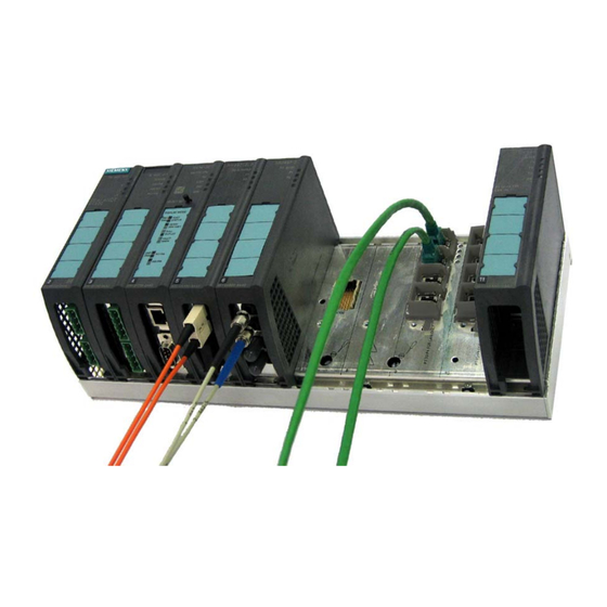
Page 47: Ports
Ethernet ports on each of slots 9 through 11. The two ports on slot 5 can be used as ring ports. Figure 3-10 Ports on the basic device Figure 3-11 Basic device with gigabit fiber-optic cable, fast Ethernet fiber-optic cable and fast Ethernet twisted pair cable Operating Instructions for SCALANCE X-400 Industrial Ethernet Switches C79000-G8976-C186-03... - Page 48 Product Description of SCALANCE X-400 Operating Instructions for SCALANCE X-400 Industrial Ethernet Switches C79000-G8976-C186-03...
-
Page 49: Media Modules, Covers, Dummy Cover
BFOC 3 km 1310 nm MM491-2LD 100Base-FX Single BFOC 26 km 1310 nm mode MM492-2 1000Base-SX Multimode 750 m 850 nm duplex MM492-2LD 1000Base-LX Single 10 km 1310 nm mode duplex Operating Instructions for SCALANCE X-400 Industrial Ethernet Switches C79000-G8976-C186-03... - Page 50 This gives you the opportunity of data transmission at a data transmission rate of 100 Mbps over multimode or single mode FOC. Figure 4-1 Slots for the media modules Operating Instructions for SCALANCE X-400 Industrial Ethernet Switches C79000-G8976-C186-03...
-
Page 51: Fast Ethernet Media Module Mm491-2 (100Base-Fx)
● In display mode C, the full duplex mode is displayed. ● In display mode D, you can see whether or not the port is monitored. Figure 4-2 Slots of the MM491-2 media module Operating Instructions for SCALANCE X-400 Industrial Ethernet Switches C79000-G8976-C186-03... -
Page 52: Fast Ethernet Media Module Mm491-2Ld (100Base-Fx)
● In display mode C, the full duplex mode is always displayed. ● In display mode D, you can see whether or not the port is monitored. Figure 4-3 Slots of the MM491-2LD media module Operating Instructions for SCALANCE X-400 Industrial Ethernet Switches C79000-G8976-C186-03... -
Page 53: Gigabit Media Module Mm492-2 (1000Base-Sx)
● In display mode C, the full duplex mode is always displayed. ● In display mode D, you can see whether or not the port is monitored. Figure 4-4 Slot of the MM492-2 media module Operating Instructions for SCALANCE X-400 Industrial Ethernet Switches C79000-G8976-C186-03... -
Page 54: Gigabit Media Module Mm492-2Ld (1000Base-Lx)
● In display mode C, the full duplex mode is always displayed. ● In display mode D, you can see whether or not the port is monitored. Figure 4-5 Slot of the MM492-2LD media module Operating Instructions for SCALANCE X-400 Industrial Ethernet Switches C79000-G8976-C186-03... -
Page 55: Covers, Dummy Cover
Available Cover Types To cover slots not used for media modules or slots for twisted pair, the following types of cover are available: ● CV490 2x1000 ● CV490 2x100 ● CV490 4x100 Operating Instructions for SCALANCE X-400 Industrial Ethernet Switches C79000-G8976-C186-03... - Page 56 Slot 5 for cover CV490 2x1000 Displays of the Cover The port status of the two electrical gigabit ports 1 and 2 are displayed on the front panel of the cover by two LEDs. Operating Instructions for SCALANCE X-400 Industrial Ethernet Switches C79000-G8976-C186-03...
- Page 57 12 through 15 of the media module extender EM496-4 if no media modules are in- serted. Figure 4-9 Slots 12 through 15 for cover CV490 2x100 on media module extender EM496-4 Operating Instructions for SCALANCE X-400 Industrial Ethernet Switches C79000-G8976-C186-03...
- Page 58 The CV490 4x100 cover can not only be used with the SCALANCE X414-3E but also for slots 12 and 13 of the twisted pair extender EM495-8. Figure 4-11 Slots 12 and 13 for the CV490 4x100 cover on the twisted pair extender module EM495-8 Operating Instructions for SCALANCE X-400 Industrial Ethernet Switches C79000-G8976-C186-03...
-
Page 59: Dummy Cover
Slot 8 of the dummy cover Displays of the Dummy Cover The LEDs of the dummy cover have no function and there is therefore no port in- formation on the front panel of the dummy cover. Operating Instructions for SCALANCE X-400 Industrial Ethernet Switches C79000-G8976-C186-03... - Page 60 Media Modules, Covers, Dummy Cover Operating Instructions for SCALANCE X-400 Industrial Ethernet Switches C79000-G8976-C186-03...
-
Page 61: Extender Modules
The transmission rate of the Ethernet ports is 10 Mbps or as a fast Ethernet port 100 Mbps. No media module is required for data transfer with this extender mod- ule. Figure 5-1 Basic device with twisted pair extender module Operating Instructions for SCALANCE X-400 Industrial Ethernet Switches C79000-G8976-C186-03... - Page 62 For slots 12 and 13 of the twisted pair extenders EM495-8, you can use the cover that can be used on slots 9 through 11 on the basic device. Two CV490 4x100 covers are supplied with the twisted pair extender. Operating Instructions for SCALANCE X-400 Industrial Ethernet Switches C79000-G8976-C186-03...
-
Page 63: Media Module Extender Em496-4
Mixed operation in slots 12 through 15 with MM491-2 and MM491-2LD modules is possible. The media module plug connectors are protected by protective caps. Connector The connectors are 2x2 BFOC sockets. Figure 5-3 Basic device with media module extender Operating Instructions for SCALANCE X-400 Industrial Ethernet Switches C79000-G8976-C186-03... - Page 64 Covers Four CV490 2x100 covers are supplied with the media module extender EM496-4. The media module plug connectors are also protected from damage by protective caps. Operating Instructions for SCALANCE X-400 Industrial Ethernet Switches C79000-G8976-C186-03...
- Page 65 Extender Modules Figure 5-5 Media module extender EM496-4 with media module MM491-2 in slot 12 and with cover Operating Instructions for SCALANCE X-400 Industrial Ethernet Switches C79000-G8976-C186-03...
- Page 66 Extender Modules Operating Instructions for SCALANCE X-400 Industrial Ethernet Switches C79000-G8976-C186-03...
-
Page 67: Installation And Commissioning
Installation and Commissioning Installing / Removing the SCALANCE X414-3E Warning SCALANCE X-400 is designed for operation with safety extra-low voltage (SELV). This means that only safety extra-low voltages (SELV) complying with IEC950/EN60950/ VDE0805 can be connected to the power supply terminals. -
Page 68: Installing / Uninstalling With An S7-300 Rail
7 and between slots 8 and 9 until the basic device can no longer be moved to the side. Note Only horizontal installation permitted (ventilation slit top/bottom). Operating Instructions for SCALANCE X-400 Industrial Ethernet Switches C79000-G8976-C186-03... - Page 69 7 and between slots 8 and 9. 3. Pull out the lower part of the basic device slightly towards the front and lift it from the S7-300 rail. Operating Instructions for SCALANCE X-400 Industrial Ethernet Switches C79000-G8976-C186-03...
-
Page 70: Installing / Uninstalling With A 35 Mm Standard Rail
Installation on a 35 mm Standard Rail Caution If the SCALANCE X-400 is liable to severe vibration (> 10 g), use the S7-300 rail for installation. The 35 mm standard rail does not provide adequate support for the SCALANCE X-400 with vibration greater than 10 g. - Page 71 1. Push the basic device down until the lower part can be pulled away from the standard rail to the front. 2. Lift the SCALANCE X414-3E up and off the standard rail. Operating Instructions for SCALANCE X-400 Industrial Ethernet Switches C79000-G8976-C186-03...
-
Page 72: Installing / Removing The Media Modules, Covers And Dummy Cover
6. Tighten the captive screw on the front of the media module with a slotted screwdriver with a 2.8 mm wide blade. 7. Secure the labeling strip on the front of the media module. Operating Instructions for SCALANCE X-400 Industrial Ethernet Switches C79000-G8976-C186-03... - Page 73 6. Fit the protective cap on the module terminal strip on the backplane of the ba- sic device. Fit the appropriate cover (see section 6.2.2) to the slot of the media module. Operating Instructions for SCALANCE X-400 Industrial Ethernet Switches C79000-G8976-C186-03...
-
Page 74: Fitting / Removing The Covers
2. At the same time, tilt the cover down at an angle, the two guides initially remain in the recesses at the lower edge of the basic device. 3. Remove the cover by pulling it upwards. Operating Instructions for SCALANCE X-400 Industrial Ethernet Switches C79000-G8976-C186-03... -
Page 75: Fitting / Removing A Dummy Cover
2. At the same time, tilt the dummy cover down at an angle, the two guides ini- tially remain in the recesses at the lower edge of the basic device. 3. Remove the dummy cover by pulling it upwards. Operating Instructions for SCALANCE X-400 Industrial Ethernet Switches C79000-G8976-C186-03... -
Page 76: Installing / Removing Extender Modules
Make sure that there is adequate clearance between the guide bolts of the ex- tender module and the basic device. In this position, the extender module should not be able to slip off, however it can be moved horizontally in both di- rections. Operating Instructions for SCALANCE X-400 Industrial Ethernet Switches C79000-G8976-C186-03... - Page 77 9. Fit the CV490 4x100 cover to slot 11 of the basic device and slots 12 and 13 of the twisted pair extender. Figure 6-4 Installing the twisted pair extender on the S7-300 rail Operating Instructions for SCALANCE X-400 Industrial Ethernet Switches C79000-G8976-C186-03...
- Page 78 9. Fit a suitable cover on slot 11 of the basic device. Note The basic device must not be used permanently without the right side panel. Operating Instructions for SCALANCE X-400 Industrial Ethernet Switches C79000-G8976-C186-03...
- Page 79 Installing the Twisted Pair Extender on the 35 mm Standard Rail Caution If the SCALANCE X-400 with extender is liable to severe vibration (> 10 g), use the S7-300 rail for installation. The 35 mm standard rail does not provide adequate support for the twisted pair extender with vibration greater than 10 g.
- Page 80 9. Fit the CV490 4x100 cover to slot 11 of the basic device and slots 12 and 13 of the twisted pair extender. Figure 6-5 Installing the twisted pair extender on the 35 mm standard rail Operating Instructions for SCALANCE X-400 Industrial Ethernet Switches C79000-G8976-C186-03...
- Page 81 8. Fit a suitable cover on slot 11 of the basic device. Note The basic device must not be used permanently without the right side panel. Operating Instructions for SCALANCE X-400 Industrial Ethernet Switches C79000-G8976-C186-03...
-
Page 82: Installing / Removing The Media Module Extender
Make sure that there is adequate clearance between the guide bolts of the ex- tender module and the basic device. In this position, the extender module should not be able to slip off, however it can be moved horizontally in both di- rections. Operating Instructions for SCALANCE X-400 Industrial Ethernet Switches C79000-G8976-C186-03... - Page 83 CV490 2x100 covers are in place. Figure 6-6 Installing the media module extender on the S7-300 rail Operating Instructions for SCALANCE X-400 Industrial Ethernet Switches C79000-G8976-C186-03...
- Page 84 8. Fit a suitable cover on slot 11 of the basic device. Note The basic device must not be used permanently without the right side panel. Operating Instructions for SCALANCE X-400 Industrial Ethernet Switches C79000-G8976-C186-03...
- Page 85 Installing the Media Module Extender on the 35 mm Standard Rail Caution If the SCALANCE X-400 with extender is liable to severe vibration (> 10 g), use the S7-300 rail for installation. The 35 mm standard rail does not provide adequate support for the media module extender with vibration greater than 10 g.
- Page 86 CV490 2x100 covers are in place. Figure 6-7 Installing the media module extender on the 35 mm standard rail Operating Instructions for SCALANCE X-400 Industrial Ethernet Switches C79000-G8976-C186-03...
- Page 87 8. Fit a suitable cover on slot 11 of the basic device. Note The basic device must not be used permanently without the right side panel. Operating Instructions for SCALANCE X-400 Industrial Ethernet Switches C79000-G8976-C186-03...
-
Page 88: Slot Numbers Of The Modules And Covers
3. Press the slot number into the recess on the front of the housing with your fin- ger. The slot number breaks out of the wheel. Figure 6-8 Slot number tabs Operating Instructions for SCALANCE X-400 Industrial Ethernet Switches C79000-G8976-C186-03... -
Page 89: Factory Defaults
When delivered, the C-PLUG is empty and is initialized with the factory settings when first started up. All subsequent configuration changes are automatically adopted in the internal memory of the SCALANCE X414-3E and in the C-PLUG. Operating Instructions for SCALANCE X-400 Industrial Ethernet Switches C79000-G8976-C186-03... -
Page 90: Ports
The redundant power supply is connected over a 4-pin connector at the front ter- minal block on the power module. Figure 6-9 Pin assignment of connector X1 Conn. 1 + 24 V power supply 1 Ground Ground + 24 V power supply 2 Operating Instructions for SCALANCE X-400 Industrial Ethernet Switches C79000-G8976-C186-03... -
Page 91: Connectors Of The Signaling Contact And Grounding Strap (X2)
When the device ships, no strap is fitted (non-grounded reference potential). Conn. 2 Floating signaling contact relay connector 1 Ground Protective earth Floating signaling contact relay connector 2 Operating Instructions for SCALANCE X-400 Industrial Ethernet Switches C79000-G8976-C186-03... -
Page 92: Digital Input Connectors (X1)
Digital input 3 Digital input 4 Warning The input voltage must not exceed + 30 V and must not fall below – 30 V, other- wise the DI module will be destroyed. Operating Instructions for SCALANCE X-400 Industrial Ethernet Switches C79000-G8976-C186-03... -
Page 93: Digital Input Connectors (X2)
DI module. Figure 6-12 Pin assignment of connector X1 (Inputs 5 through 8) Conn. 2 Digital input 5 Digital input 6 Ground Digital input 7 Digital input 8 Operating Instructions for SCALANCE X-400 Industrial Ethernet Switches C79000-G8976-C186-03... -
Page 94: Connectors For The Twisted Pair Cables
The flexible eight-wire patch cable (TP cord) for gigabit transmission allows a maxi- mum cable length of 10 m. Figure 6-13 FastConnect Cabling TP cord (1 Gbps) IE FC Standard Cable 2x2 (100 Mbps) Operating Instructions for SCALANCE X-400 Industrial Ethernet Switches C79000-G8976-C186-03... - Page 95 2 RJ-45 jacks each with 2x2 wire cable for 100 Mbps With the IE FC RJ-45 modular outlet insert 1GE, the eight-wire FastConnect cable allows a transmission rate of 1 Gbps. Figure 6-14 IE FC RJ-45 Modular Outlet Insert 1GE Operating Instructions for SCALANCE X-400 Industrial Ethernet Switches C79000-G8976-C186-03...
- Page 96 With the IE FC RJ-45 modular outlet insert 2FE, the eight-wire FastConnect cable is split over two RJ-45 jacks and allows a transmission rate of 2 x 100 Mbps. Figure 6-15 IE FC RJ-45 Modular Outlet Insert 2FE Operating Instructions for SCALANCE X-400 Industrial Ethernet Switches C79000-G8976-C186-03...
- Page 97 The remaining 10 m is then available for TP cord at both ends (total of 10 m). Figure 6-16 FastConnect Cabling TP Cord 4x2 TP Cord 4x2 IE FC Standard Cable 4x2 Operating Instructions for SCALANCE X-400 Industrial Ethernet Switches C79000-G8976-C186-03...
- Page 98 If this is the situation, do the following: 1. Press the catch on the RJ-45 plug to the left with a small screwdriver. 2. Remove the cable. Figure 6-17 Releasing the FastConnect RJ-45 plug Operating Instructions for SCALANCE X-400 Industrial Ethernet Switches C79000-G8976-C186-03...
-
Page 99: Connectors For Fiber-Optic Cables
Fiber-optic cable connectors are susceptible to contamination and mechanical damage to the face. Protect open connections with the supplied dust caps. Figure 6-18 SC Duplex plug with gigabit media module MM492-2LD Operating Instructions for SCALANCE X-400 Industrial Ethernet Switches C79000-G8976-C186-03... - Page 100 Fiber-optic cable connectors are susceptible to contamination and mechanical damage to the face. Protect open connections with the supplied dust caps. Figure 6-19 BFOC plug with fast Ethernet media module MM491-2 Operating Instructions for SCALANCE X-400 Industrial Ethernet Switches C79000-G8976-C186-03...
-
Page 101: Operator Controls
Below the labeling strip on the Switch CPU, on slot 4, there are four DIL switches. These DIL switches can have one of two states ( ON / OFF ). Figure 6-20 Power module, digital inputs and Switch CPU with controls Operating Instructions for SCALANCE X-400 Industrial Ethernet Switches C79000-G8976-C186-03... - Page 102 Ports 1 and 2 of slot 6 are ring ports. Port 1 of slot 6 is first ring port. Port 1 of slot 7 is second ring port. No ring redundancy. When shipped, the factory settings apply (see section 6.5). Operating Instructions for SCALANCE X-400 Industrial Ethernet Switches C79000-G8976-C186-03...
- Page 103 OFF , otherwise ports in slots 6 and 7 will be defined as ring ports that are only available when media modules are plugged in. Figure 6-21 Ring ports that can be defined with switches R1 and R2 Operating Instructions for SCALANCE X-400 Industrial Ethernet Switches C79000-G8976-C186-03...
- Page 104 ● Switch 3: In the schematic below, switch R1 is set to OFF and R2 is set to ON . Figure 6-22 The three possible settings for ring ports with R1 and R2 Operating Instructions for SCALANCE X-400 Industrial Ethernet Switches C79000-G8976-C186-03...
-
Page 105: Select / Set Button
2 seconds, the current states of all ports and the states of the power sup- plies L1 and L2 are included in the fault mask. The previous fault mask is then overwritten. Operating Instructions for SCALANCE X-400 Industrial Ethernet Switches C79000-G8976-C186-03... -
Page 106: Led Display
Signal at input Signal at input Signal at input IN4/IN8 put IN4 Device is operating as RM STBY Reserved (no function) Port status Transmission Half / full du- Fault mask rate plex Operating Instructions for SCALANCE X-400 Industrial Ethernet Switches C79000-G8976-C186-03... -
Page 107: Startup Behavior Of The Scalance X414-3E
During ope- Fault occurred Problem-free op- eration ration Figure 6-23 Fault LED on the power module Operating Instructions for SCALANCE X-400 Industrial Ethernet Switches C79000-G8976-C186-03... -
Page 108: Selecting The Display Modes
CPU in the required combination. The selected display mode is then ac- tivated. There is an automatic switchover to DMode A if the button is not pressed for longer than one minute. Figure 6-24 Display of the four possible display modes Operating Instructions for SCALANCE X-400 Industrial Ethernet Switches C79000-G8976-C186-03... -
Page 109: Led Display - Power Module
Power supply L1 lower than 17 V. Green Power supply L1 higher than 17 V. Power supply L2 lower than 17 V. Green Power supply L2 higher than 17 V. Operating Instructions for SCALANCE X-400 Industrial Ethernet Switches C79000-G8976-C186-03... - Page 110 Power supply L2 is not monitored. If L2 falls below 17 V, the signaling contact does not respond. Green Power supply L2 is monitored. If L2 falls below 17 V, the signaling contact responds. Operating Instructions for SCALANCE X-400 Industrial Ethernet Switches C79000-G8976-C186-03...
-
Page 111: Led Display - Di Module
DM1 DM2 IN1/5 IN2/6 IN3/7 IN4/8 Meaning DMode B Digital inputs DMode D IN5 through IN8 Signal at input IN5 Signal at input IN6 Signal at input IN7 Signal at input IN8 Operating Instructions for SCALANCE X-400 Industrial Ethernet Switches C79000-G8976-C186-03... -
Page 112: Led Display - Switch Cpu
SCALANCE X414-3E has switched through. STBY No function, reserved for future applica- tions. Green Display of the display mode. Green Display of the display mode. Operating Instructions for SCALANCE X-400 Industrial Ethernet Switches C79000-G8976-C186-03... -
Page 113: Led Display Of The Ports (Dmode A Through Dmode D)
Port turned off by management. period flashes four times per pe- Port is monitored port. riod Yel- flashes / lit Receiving data at port. Figure 6-29 Display of the port status of port 1 Operating Instructions for SCALANCE X-400 Industrial Ethernet Switches C79000-G8976-C186-03... - Page 114 DMode B, the desired status, in other words the set transmission rate (1000 Mbps, 100 Mbps, 10 Mbps) continues to be displayed. If there is a link fault and autone- gotiation is active, the port LED goes off. Operating Instructions for SCALANCE X-400 Industrial Ethernet Switches C79000-G8976-C186-03...
- Page 115 DMode C, the desired status, in other words the set type of transmission (full or half duplex) continues to be displayed. If there is a link fault and autonegotiation is active, the port LED goes off. Operating Instructions for SCALANCE X-400 Industrial Ethernet Switches C79000-G8976-C186-03...
- Page 116 (for example cable not plugged in or connected device turned off), this triggers the sig- naling contact and the fault state is adopted. Figure 6-32 Example: Monitoring of port 1 is "on“ Operating Instructions for SCALANCE X-400 Industrial Ethernet Switches C79000-G8976-C186-03...
-
Page 117: Replacing The C-Plug
The notch in the casing must be on the right. The C-PLUG is inserted by pressing it into the receptacle until the C-PLUG is flush with the front surface of the CPU. Figure 6-33 Removing the C-PLUG Operating Instructions for SCALANCE X-400 Industrial Ethernet Switches C79000-G8976-C186-03... -
Page 118: Show Location
With the PST Tool V3.0, you can trigger this function with Module \ Ring . For more detailed information, refer to the Configuration Manual SCALANCE X-400 , chapter Working with the Primary Setup Tool , section Deter- mining the location of a device . -
Page 119: Technical Specifications
DEHN Blitzduc- tor VT AD 24V, article no. 918 402 is used Power consumption (without modules) 15 W at 24 V DC Current consumption at 24 V DC < 2000 mA Operating Instructions for SCALANCE X-400 Industrial Ethernet Switches C79000-G8976-C186-03... - Page 120 50 (for reconfiguration time < 0.3 s) Switching Properties Max. number of learnable addresses 8000 Aging time (default) 40 s Switching procedure Store and forward Latency (store and forward time) 5 µs Operating Instructions for SCALANCE X-400 Industrial Ethernet Switches C79000-G8976-C186-03...
- Page 121 Fast Ethernet media module MM491-2 138.3 years 6GK5 491-2AB00-8AA2 Fast Ethernet media module MM491-2LD 141.8 years 6GK5 491-2AC00-8AA2 Gigabit media module MM492-2 400.5 years 6GK5 492-2AL00-8AA2 Gigabit media module MM492-2LD 400.5 years 6GK5 492-2AM00-8AA2 Operating Instructions for SCALANCE X-400 Industrial Ethernet Switches C79000-G8976-C186-03...
- Page 122 Technical Specifications Figure 7-1 Dimension drawing - SCALANCE X414-3E Operating Instructions for SCALANCE X-400 Industrial Ethernet Switches C79000-G8976-C186-03...
-
Page 123: Media Module Mm491-2 (100Base-Fx)
EN 55081 Class A Noise immunity EN 61000-6-2 : 2001 Construction Dimensions (W x H x D) 35 x 145 x 90 mm Weight 260 g Degree of protection IP 20 Operating Instructions for SCALANCE X-400 Industrial Ethernet Switches C79000-G8976-C186-03... -
Page 124: Media Module Mm491-2Ld (100Base-Fx)
EN 61000-6-2 : 2001 Laser protection Class 1 complying with IEC 60825 -1 Construction Dimensions (W x H x D) 35 x 145 x 90 mm Weight 260 g Degree of protection IP 20 Operating Instructions for SCALANCE X-400 Industrial Ethernet Switches C79000-G8976-C186-03... -
Page 125: Media Module Mm492-2 (1000Base-Sx)
EN 61000-6-2 : 2001 Laser protection Class 1 complying with IEC 60825 -1 Construction Dimensions (W x H x D) 35 x 145 x 90 mm Weight 250 g Degree of protection IP 20 Operating Instructions for SCALANCE X-400 Industrial Ethernet Switches C79000-G8976-C186-03... -
Page 126: Media Module Mm492-2Ld (1000Base-Lx)
EN 61000-6-2 : 2001 Laser protection Class 1 complying with IEC 60825 -1 Construction Dimensions (W x H x D) 35 x 145 x 90 mm Weight 250 g Degree of protection IP 20 Operating Instructions for SCALANCE X-400 Industrial Ethernet Switches C79000-G8976-C186-03... -
Page 127: Extender Module Em495-8
EN 55081 Class A Noise immunity EN 61000-6-2 : 2001 Construction Dimensions (W x H x D) 86 x 145 x 112,4 mm Weight 560 g Degree of protection IP 20 Operating Instructions for SCALANCE X-400 Industrial Ethernet Switches C79000-G8976-C186-03... - Page 128 Technical Specifications Figure 7-2 Dimension drawing - extender module EM495-8 Operating Instructions for SCALANCE X-400 Industrial Ethernet Switches C79000-G8976-C186-03...
-
Page 129: Extender Module Em496-4
EN 55081 Class A Noise immunity EN 61000-6-2 : 2001 Construction Dimensions (W x H x D) 154 x 145 x 112,4 mm Weight 980 g Degree of protection IP 20 Operating Instructions for SCALANCE X-400 Industrial Ethernet Switches C79000-G8976-C186-03... - Page 130 Technical Specifications Figure 7-3 Dimension drawing - extender module EM496-4 Operating Instructions for SCALANCE X-400 Industrial Ethernet Switches C79000-G8976-C186-03...
-
Page 131: Approvals, Certificates
CE Marking SIMATIC NET SCALANCE X-400 Industrial Ethernet switches meet the require- ments and aims of the following EU directives and comply with the harmonized European standards (EN) for programmable logic controllers published in the Offi- cial Journal of the European Communities: ●... -
Page 132: Emc Directive
The listed media modules meet the FDA and IEC requirements. ● MM491-2LD ● MM492-2 ● MM492-2LD Figure 8-1 FDA and IEC labels FDA and IEC labels are not required for media module MM491-2. Operating Instructions for SCALANCE X-400 Industrial Ethernet Switches C79000-G8976-C186-03... -
Page 133: Installation Guidelines
The products meet the requirements if you adhere to the installation and safety in- structions contained in these Operating Instructions SIMATIC NET Industrial Ethernet SCALANCE X-400 and in the following documentation: SIMATIC NET Industrial Twisted Pair and Fiber Optic Networks Manual /2/ This documentation is available on the Internet at http://support.automation.siemens.com/WW/view/en/8763736... - Page 134 Underwriters Laboratories (UL) complying with Standard UL 508 Report number E85972 CSA Approval Information Technology Equipment CSA-Certification-Mark Canadian Standard Association CSA C22.2 No. 60950-1-03 CSA Approval Industrial Control Equipment CSA-Certification-Mark Canadian Standard Association CSA C22.2 No. 14-M91 Operating Instructions for SCALANCE X-400 Industrial Ethernet Switches C79000-G8976-C186-03...
- Page 135 Cl. 1, Zone 2, Aex nC IIC T4 Note When used in environments corresponding to Class I, Division 2 (see above), the product must be installed in a cabinet, a suitable enclosure, or closed room. Operating Instructions for SCALANCE X-400 Industrial Ethernet Switches C79000-G8976-C186-03...
- Page 136 In hazardous areas, personal injury or damage to property may occur if you make or break an electrical circuit while a SCALANCE X-400 is in operation. Do not connect or disconnect any live circuits unless risk of explosion can be exc- luded with certainty.
- Page 137 EU directive at the following address: Siemens Aktiengesellschaft Automation and Drives Industrial Communication SIMATIC NET Postfach 4848 D-90327 Nuernberg, Germany This declaration certifies compliance with the directives named above, but does not guarantee any specific properties. Operating Instructions for SCALANCE X-400 Industrial Ethernet Switches C79000-G8976-C186-03...
- Page 138 Approvals, Certificates Operating Instructions for SCALANCE X-400 Industrial Ethernet Switches C79000-G8976-C186-03...
-
Page 139: Glossary
C-PLUG. Command Line Interpreter. Terminal-based configuration option for the SCALANCE X-400. The CLI can be used both over the serial port of the Switch CPU and with TELNET over every Ethernet port. Collision domain To ensure that the CSMA/CD protocol functions correctly, the propaga- tion time of a data packet from one node to another is restricted. - Page 140 Glossary Connection monitor- With regular link test pulses, SCALANCE X-400 monitors the con- nected TP and FO cable segments for short-circuits or interruptions. The SCALANCE does not send data to a segment from which it is not receiving link test pulses.
- Page 141 This prevents circulating frames and, if a fault develops, provides an alternative path within one second (reconfiguration time). Reconfiguration time The time required to restore a functional configuration if a device fails or a network cable is interrupted. Operating Instructions for SCALANCE X-400 Industrial Ethernet Switches C79000-G8976-C186-03...
- Page 142 Spanning Tree The Spanning Tree protocol (STP) allows redundant transmission paths. This prevents circulating frames and, if a fault develops, pro- vides an alternative path within 20 - 30 seconds (reconfiguration time). Operating Instructions for SCALANCE X-400 Industrial Ethernet Switches C79000-G8976-C186-03...
- Page 143 LAN or on the Internet. The user then has the same options as when directly connected to this device with a terminal. TP Port Port with a TP connector (RJ-45 jack) VLAN Virtual LAN within a physically existing network. Operating Instructions for SCALANCE X-400 Industrial Ethernet Switches C79000-G8976-C186-03...
- Page 144 Glossary Operating Instructions for SCALANCE X-400 Industrial Ethernet Switches C79000-G8976-C186-03...
-
Page 145: Index
Optical ring ......... 14 Industrial Ethernet ........12 Installation ..........67 Serial port..........43 Signaling contact ........40 Slots ............36 LED display ........... 106 Spanning tree...........22 DI module..........111 Spares............36 Ports..........113 Splitting ring ports ........21 Power module........109 Operating Instructions for SCALANCE X-400 Industrial Ethernet Switches C79000-G8976-C186-03... - Page 146 Topologies ..........13 Twisted pair cable........25 Line structure ........18 Ring with redundancy manager..13 Star structure ........16 VLAN............22 Transmission medium ......25 Multimode fiber-optic cable....27 Wavelength ..........27 Single mode fiber-optic cable .....27 Operating Instructions for SCALANCE X-400 Industrial Ethernet Switches C79000-G8976-C186-03...
- Page 147 Worldwide (Nuernberg) Technical Support 24 hours a day, 365 days a year Phone: +49 (0) 180 5050-222 Fax: +49 (0) 180 5050-223 Internet: www.siemens.de/ automation/support- request GMT: +1:00 Europe / Africa (Nuernberg) United States (Johnson City) Asia / Australia (Beijing)
- Page 148 A&D Technical Support Service & Support on the Internet In addition to our documentation, we offer our Know-how online on the internet at: http://www.siemens.com/automation/service&support where you will find the following: • The newsletter, which constantly provides you with up-to-date information on your products.
Need help?
Do you have a question about the SCALANCE X-400 and is the answer not in the manual?
Questions and answers