Siemens SCALANCE X-100 Operating Instructions Manual
Industrial ethernet switches
Hide thumbs
Also See for SCALANCE X-100:
- Commissioning manual (121 pages) ,
- Operating instructions manual (296 pages)
Table of Contents
Advertisement
SIMATIC NET
Industrial Ethernet switches
SCALANCE X-100
Operating Instructions
12/2016
A2B00060666-08
___________________
Introduction
___________________
Network topologies
___________________
Description of the device
___________________
Assembly
___________________
Connecting up
___________________
Maintenance and
troubleshooting
___________________
Technical specifications
___________________
Certifications and approvals
___________________
Dimension drawings
1
2
3
4
5
6
7
8
9
Advertisement
Table of Contents

Related Manuals for Siemens SCALANCE X-100


Summary of Contents for Siemens SCALANCE X-100
- Page 1 ___________________ Introduction ___________________ Network topologies ___________________ SIMATIC NET Description of the device ___________________ Assembly Industrial Ethernet switches SCALANCE X-100 ___________________ Connecting up ___________________ Maintenance and troubleshooting Operating Instructions ___________________ Technical specifications ___________________ Certifications and approvals ___________________ Dimension drawings 12/2016 A2B00060666-08...
-
Page 2: Legal Information
Note the following: WARNING Siemens products may only be used for the applications described in the catalog and in the relevant technical documentation. If products and components from other manufacturers are used, these must be recommended or approved by Siemens. Proper transport, storage, installation, assembly, commissioning, operation and maintenance are required to ensure that the products operate safely and without any problems. -
Page 3: Table Of Contents
Introduction ............................. 5 On the Operating Instructions ....................5 On the product .......................... 7 Network topologies ..........................11 Description of the device ........................13 Overview of the SCALANCE X-100 ..................13 Product properties ........................14 3.2.1 SCALANCE X104-2 ........................ 14 3.2.2 SCALANCE X106-1 ........................ - Page 4 EU declaration of conformity ....................62 8.1.1 ATEX ............................63 8.1.2 EMC ............................64 8.1.3 RoHS ............................64 8.1.4 Products ..........................65 ATEX (KEMA 07 ATEX0145 X) ..................... 65 Dimension drawings ..........................69 Index ..............................75 SCALANCE X-100 Operating Instructions, 12/2016, A2B00060666-08...
-
Page 5: Introduction
On the Operating Instructions Purpose of the Operating Instructions These Operating Instructions support you when commissioning networks with the Industrial Ethernet switches of the SCALANCE X-100 product line. Validity of the Operating Instructions These operating instructions are valid for the following devices:... - Page 6 In order to protect plants, systems, machines and networks against cyber threats, it is necessary to implement – and continuously maintain – a holistic, state-of-the-art industrial security concept. Siemens’ products and solutions only form one element of such a concept. Customer is responsible to prevent unauthorized access to its plants, systems, machines and networks.
-
Page 7: On The Product
To comply with EU Directive 94/9 (ATEX95), this enclosure must meet the requirements of at least IP54 in compliance with EN 60529. WARNING EXPLOSION HAZARD DO NOT CONNECT OR DISCONNECT EQUIPMENT WHEN A FLAMMABLE OR COMBUSTIBLE ATMOSPHERE IS PRESENT. SCALANCE X-100 Operating Instructions, 12/2016, A2B00060666-08... -
Page 8: Operating Instructions, 12/2016, A2B00060666
Introduction 1.2 On the product Components of the product The following components are supplied with a SCALANCE X-100: ● IE Switch SCALANCE X-100 ● 2-pin plug-in terminal block (signaling contact) ● 4-pin plug-in terminal block (power supply) ● Product information... - Page 9 • Place the modules only on conductive surfaces. • Pack, store and transport electronic modules and components only in conductive packaging such as metalized plastic or metal containers, conductive foam or household aluminum foil. SCALANCE X-100 Operating Instructions, 12/2016, A2B00060666-08...
- Page 10 Introduction 1.2 On the product SCALANCE X-100 Operating Instructions, 12/2016, A2B00060666-08...
-
Page 11: Network Topologies
Switching technology allows extensive networks to be set up with numerous nodes and simplifies network expansion. Which topologies can be implemented? Using the IE switches of the SCALANCE X-100 product line, you can implement star topologies. Note Keep to the maximum permitted cable lengths of the devices you are using. You will find the permitted cable lengths in the section "Technical specifications (Page 43)". - Page 12 Network topologies Figure 2-2 Example of an electrical/optical star topology with SCALANCE X112-2 and SCALANCE X104-2 SCALANCE X-100 Operating Instructions, 12/2016, A2B00060666-08...
-
Page 13: Description Of The Device
Description of the device Overview of the SCALANCE X-100 Table 3- 1 Overview of the product characteristics Device type SCALANCE X104-2 X10⁶-1 X108 X108PoE X112-2 X116 X124 SIMATIC environment Diagnostics LED 24 VDC 2 x 24 VDC Compact housing (securing collar, etc.) -
Page 14: Product Properties
The SCALANCE X104-2 has four RJ-45 jacks and two BFOC sockets for the connection of end devices or other network segments. Note The BFOC socket (Bayonet Fiber Optic Connector) corresponds to the ST socket. Figure 3-1 SCALANCE X104-2 SCALANCE X-100 Operating Instructions, 12/2016, A2B00060666-08... -
Page 15: Scalance X106-1
The SCALANCE X106-1 has six RJ-45 jacks and a BFOC socket for the connection of end devices or other network segments. Note The BFOC socket (Bayonet Fiber Optic Connector) corresponds to the ST socket. Figure 3-2 SCALANCE X106-1 SCALANCE X-100 Operating Instructions, 12/2016, A2B00060666-08... -
Page 16: Scalance X108
Description of the device 3.2 Product properties 3.2.3 SCALANCE X108 Possible connections The SCALANCE X108 has eight RJ-45 jacks for the connection of end devices or other network segments. Figure 3-3 SCALANCE X108 SCALANCE X-100 Operating Instructions, 12/2016, A2B00060666-08... -
Page 17: Scalance X108Poe
With a 100 m long cable connected, the end device then has a maximum of 12.95 W available. You will find more information on the PoE function in the section "TP ports (Page 20)". SCALANCE X-100 Operating Instructions, 12/2016, A2B00060666-08... -
Page 18: Scalance X112-2
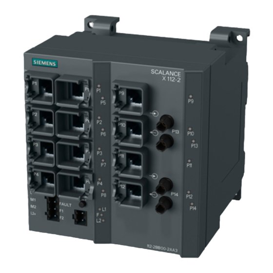
The SCALANCE X112-2 has twelve RJ-45 jacks and two BFOC sockets for the connection of end devices or other network segments. Note The BFOC socket (Bayonet Fiber Optic Connector) corresponds to the ST socket. Figure 3-5 SCALANCE X112-2 SCALANCE X-100 Operating Instructions, 12/2016, A2B00060666-08... -
Page 19: Scalance X116
Description of the device 3.2 Product properties 3.2.6 SCALANCE X116 Possible connections The SCALANCE X116 has 16 RJ-45 jacks for the connection of end devices or other network segments. Figure 3-6 SCALANCE X116 SCALANCE X-100 Operating Instructions, 12/2016, A2B00060666-08... -
Page 20: Scalance X124
TP ports (twisted pair) Note Strain relief of the interfaces To prevent weights or mechanical movement that can affect an interface causing interrupted contact, fix the cables to a cable guide or rail at short intervals. SCALANCE X-100 Operating Instructions, 12/2016, A2B00060666-08... - Page 21 Description of the device 3.3 TP ports (twisted pair) RJ-45 connector pinout With SCALANCE X-100, the twisted-pair port is designed as an RJ-45 jack with MDI-X pin assignment (Medium Dependent Interface Autocrossover) of a network component. Special features of the SCALANCE X108PoE...
- Page 22 Devices not supporting autonegotiation must be set permanently to 100 Mbps half duplex or 10 Mbps half duplex. Note The IE switches of the SCALANCE X-100 product line are plug-and-play devices that require no settings during commissioning. Auto polarity exchange If the pair of receiving cables is connected incorrectly (RD+ and RD- interchanged), the polarity is adapted automatically.
-
Page 23: Fo Port (Fiber Optic)
Description of the device 3.4 FO port (fiber optic) The IE Switches SCALANCE X-100 all support the MDI / MDI-X autocrossover function. NOTICE Formation of loops Note that the direct connection of two ports or accidental connection over several switches causes an illegal loop that can cause network overload and failure. -
Page 24: Led Display
The port LEDs indicate the status of the ports. LED color LED status Meaning Green Link exists, no data reception at port Yellow Link exists, data reception at port Yellow Flashing Setting or display of the fault mask SCALANCE X-100 Operating Instructions, 12/2016, A2B00060666-08... -
Page 25: Set Button
If you release the SET button as soon as the LEDs light up, the current settings will be stored. The stored status is displayed. The monitored ports are indicated by statically lit LEDs. • The monitored power supply is indicated by statically lit LEDs. • SCALANCE X-100 Operating Instructions, 12/2016, A2B00060666-08... - Page 26 If the link is lost (link down) at a monitored port or a monitored power supply is lost, this is signaled as follows: ● The red fault LED lights up. ● The signaling contact is opened. SCALANCE X-100 Operating Instructions, 12/2016, A2B00060666-08...
-
Page 27: Assembly
EXPLOSION HAZARD Replacing components may impair suitability for Class 1, Division 2 or Zone 2. WARNING The device may only be operated in an environment with pollution degree 1 or 2 (see IEC 60664-1). SCALANCE X-100 Operating Instructions, 12/2016, A2B00060666-08... - Page 28 Warming and premature aging of the IE switch due to direct sunlight Direct sunlight can heat up the device and can lead to premature aging of the IE switch and its cabling. Provide suitable shade to protect the IE switch against direct sunlight. SCALANCE X-100 Operating Instructions, 12/2016, A2B00060666-08...
-
Page 29: Types Of Installation
1. Place the second housing guide of the device on the top edge of the DIN rail. 2. Press the device down against the DIN rail until the spring catch locks in place. 3. Fit the connectors for the power supply. See also section "Power supply (Page 37)". SCALANCE X-100 Operating Instructions, 12/2016, A2B00060666-08... - Page 30 To remove the device from the DIN rail, follow the steps below: 1. Disconnect all connected cables. 2. Release the DIN rail catch on the bottom of the device using a screwdriver. 3. Pull the lower part of the device away from the DIN rail. SCALANCE X-100 Operating Instructions, 12/2016, A2B00060666-08...
-
Page 31: Installation On A Standard Rail
1. Place the first housing guide of the device on the top edge of the S7-300 standard rail. 2. Screw the device to the underside of the standard rail (tightening torque 2 Nm). 3. Fit the connectors for the power supply. See also section "Power supply (Page 37)". SCALANCE X-100 Operating Instructions, 12/2016, A2B00060666-08... - Page 32 To remove the device from the S7-300 standard rail, follow the steps below: 1. Disconnect all connected cables. 2. Release the screw holding the device on the bottom of the standard rail. 3. Lift the device off the standard rail. SCALANCE X-100 Operating Instructions, 12/2016, A2B00060666-08...
-
Page 33: Wall Mounting
2. Screw the device to the wall using the keyhole hang-up mechanisms. 3. Fit the connectors for the power supply, see the section "Power supply (Page 37)". 4. Fit the connectors for the signaling contact, refer to the section ""Signaling contacts (Page 38)". SCALANCE X-100 Operating Instructions, 12/2016, A2B00060666-08... - Page 34 Assembly 4.5 Wall mounting SCALANCE X-100 Operating Instructions, 12/2016, A2B00060666-08...
-
Page 35: Connecting Up
Safety notices on use in hazardous areas General safety notices relating to protection against explosion WARNING EXPLOSION HAZARD Do not connect or disconnect cables to or from the device when a flammable or combustible atmosphere is present. SCALANCE X-100 Operating Instructions, 12/2016, A2B00060666-08... - Page 36 WARNING Take measures to prevent transient voltage surges of more than 40% of the rated voltage. This is the case if you only operate devices with SELV (safety extra-low voltage). SCALANCE X-100 Operating Instructions, 12/2016, A2B00060666-08...
-
Page 37: Power Supply
The power supply is connected over a high resistance with the enclosure to allow an ungrounded set up. The two power supplies are non-floating. The following figure shows the position of the power supply of the SCALANCE X-100 IE switches and the assignment of the terminal block. -
Page 38: Signaling Contact
The signaling contact can be subjected to a maximum load of 100 mA (safety extra-low voltage SELV, 24 VDC). Higher voltages or currents can damage the device! The following figure shows the position of the signaling contacts of the SCALANCE X-100 IE switches and the assignment of the terminal block. Pin number... -
Page 39: Grounding
Fitting the IE FC RJ45 Plug 180 to the IE FC Standard Cable You will find the notes on installation in the instructions that ship with the IE FC RJ45 Plug 180. Figure 5-1 IE FC 45 Plug 180 SCALANCE X-100 Operating Instructions, 12/2016, A2B00060666-08... - Page 40 If there is not enough space to release the lock with your hand, you can also use a 2.5 mm screwdriver. You can then remove the IE FC RJ45 Plug 180 from the RJ-45 jack. SCALANCE X-100 Operating Instructions, 12/2016, A2B00060666-08...
-
Page 41: Maintenance And Troubleshooting
Possible sources of problems and how to deal with them Fuses Some of the Industrial Ethernet switches of the SCALANCE X-100 product line have a resettable fuse / PTC. If the fuse triggers (all LEDs are off despite correctly applied power supply), the device should be disconnected from the power supply for approximately 30 minutes before turning it on again. -
Page 42: Scalance X
Maintenance and troubleshooting 6.1 Possible sources of problems and how to deal with them SCALANCE X-100 Operating Instructions, 12/2016, A2B00060666-08... -
Page 43: Technical Specifications
50/125 μm 0 to 5000 m • • Attenuation ≤ 1 dB/km at 1300 nm 1200 MHz x km at 1300 nm 6 dB max. permitted FO cable attenuation with 3 dB link power margin SCALANCE X-100 Operating Instructions, 12/2016, A2B00060666-08... - Page 44 Switching properties Aging time 30 seconds Max. number of learnable MAC ad- 2048 dresses Response to LLDP frames Blocking Response to spanning tree BPDU Forwarding frames CoS acc. to IEEE 802.1Q QoS priority queues SCALANCE X-100 Operating Instructions, 12/2016, A2B00060666-08...
-
Page 45: Scalance X106-1
The number of SCALANCE X Industrial Ethernet switches connected in a line influences the frame delay time. When a frame passes through devices of the SCALANCE X-100 product line, it is delayed by the store and forward function of the switch •... - Page 46 136.65 years Housing material Basic housing Die cast aluminum, powder coated Front cover Polyphenylene ether + polystyrene (PPE+PS plastic) Weight 780 g Dimensions (W x H x D) 60 x 125 x 124 mm SCALANCE X-100 Operating Instructions, 12/2016, A2B00060666-08...
- Page 47 The number of SCALANCE X Industrial Ethernet switches connected in a line influences the frame delay time. When a frame passes through devices of the SCALANCE X-100 product line, it is delayed by the store and forward function of the switch •...
-
Page 48: Scalance X108
During operation ≤ 95 % no condensation Operating altitude During operation ≤ 2,000 m above sea level at max. 56 °C ambient temperature ≤ 3,000 m above sea level at max. 50 °C ambient temperature SCALANCE X-100 Operating Instructions, 12/2016, A2B00060666-08... - Page 49 The number of SCALANCE X Industrial Ethernet switches connected in a line influences the frame delay time. When a frame passes through devices of the SCALANCE X-100 product line, it is delayed by the store and forward function of the switch •...
-
Page 50: Scalance X108Poe
During operation ≤ 95 % no condensation Operating altitude During operation ≤ 2,000 m above sea level at max. 56 °C ambient temperature ≤ 3,000 m above sea level at max. 50 °C ambient temperature SCALANCE X-100 Operating Instructions, 12/2016, A2B00060666-08... - Page 51 The number of SCALANCE X Industrial Ethernet switches connected in a line influences the frame delay time. When a frame passes through devices of the SCALANCE X-100 product line, it is delayed by the store and forward function of the switch •...
-
Page 52: Scalance X112-2
Multimode glass FO cable, cable cross sections 62.5/125 μm and 50/125 μm Permitted cable length (glass FO Cable cross-section Permitted cable length cable) 62.5/125 μm 0 to 4000 m • • 50/125 μm 0 to 5000 m • • SCALANCE X-100 Operating Instructions, 12/2016, A2B00060666-08... - Page 53 Installation on an S7-300 standard rail • Wall mounting • Switching properties Aging time 30 seconds Max. number of learnable MAC ad- 2048 dresses Response to LLDP frames Blocking Response to spanning tree BPDU Forwarding frames SCALANCE X-100 Operating Instructions, 12/2016, A2B00060666-08...
-
Page 54: Scalance X116
The number of SCALANCE X Industrial Ethernet switches connected in a line influences the frame delay time. When a frame passes through devices of the SCALANCE X-100 product line, it is delayed by the store and forward function of the switch •... - Page 55 Installation on an S7-300 standard rail • Wall mounting • Switching properties Aging time 30 seconds Max. number of learnable MAC ad- 2048 dresses Response to LLDP frames Blocking Response to spanning tree BPDU Forwarding frames SCALANCE X-100 Operating Instructions, 12/2016, A2B00060666-08...
-
Page 56: Scalance X124
The number of SCALANCE X Industrial Ethernet switches connected in a line influences the frame delay time. When a frame passes through devices of the SCALANCE X-100 product line, it is delayed by the store and forward function of the switch •... - Page 57 Installation on an S7-300 standard rail • Wall mounting • Switching properties Aging time 30 seconds Max. number of learnable MAC ad- 2048 dresses Response to LLDP frames Blocking Response to spanning tree BPDU Forwarding frames SCALANCE X-100 Operating Instructions, 12/2016, A2B00060666-08...
- Page 58 The number of SCALANCE X Industrial Ethernet switches connected in a line influences the frame delay time. When a frame passes through devices of the SCALANCE X-100 product line, it is delayed by the store and forward function of the switch •...
-
Page 59: Mechanical Stability (In Operation)
5 - 8.51 Hz: 3.5 mm 150 m/s , 16 ms duration 8.51 - 500 Hz: 10 m/s 6 shocks per axis 1 oct/min, 10 cycles X112-2 ● ● X116 ● ● X124 ● ● SCALANCE X-100 Operating Instructions, 12/2016, A2B00060666-08... - Page 60 Technical specifications 7.8 Mechanical stability (in operation) SCALANCE X-100 Operating Instructions, 12/2016, A2B00060666-08...
-
Page 61: Certifications And Approvals
You can check which of the following approvals have been granted for your product by the markings on the type plate. Current approvals on the Internet You will find the current approvals for the product on the Internet pages of Siemens Industry Online Support (https://support.industry.siemens.com/cs/ww/en/ps/15273/cert). Notes for the manufacturers of machines The devices are not machines in the sense of the EC Machinery Directive. -
Page 62: Eu Declaration Of Conformity
DE-76181 Karlsruhe Germany You will find the EC declaration of conformity for these products on the Internet pages of Siemens Industry Online Support (https://support.industry.siemens.com/cs/ww/en/ps/15273/cert). The SIMATIC NET products described in these Operating Instructions meet the requirements of the following EC directives: ●... -
Page 63: Atex
Potentially Explosive Atmospheres”. Applied standard: ● EN 60079-0 Hazardous areas - Part 0: Equipment - General requirements ● EN 60079-15 Explosive atmospheres - Part 15: Device protection by type of protection See also Products (Page 65) SCALANCE X-100 Operating Instructions, 12/2016, A2B00060666-08... -
Page 64: Emc
EC directive 2011/65/EC for the restriction of the use of certain hazardous substances in electrical and electronic equipment: Applied standard: EN 50581 Technical documentation for the assessment electrical and electronic products with respect to restriction of hazardous substances SCALANCE X-100 Operating Instructions, 12/2016, A2B00060666-08... -
Page 65: Products
Area". You will find this document • on the data medium that ships with some devices. • on the Internet pages of Siemens Industry Online Support (http://support.automation.siemens.com/WW/view/en). Enter the document identification number C234 as the search term. The SIMATIC NET products meet the requirements of the EC directive 94/9/EC "Equipment and Protective Devices for Use in Potentially Explosive Atmospheres”. - Page 66 Non Incendive / Class I / Zone 2 / Group IIC / T4 cULus Approval for Information Technology Equipment cULus Listed I. T. E. Underwriters Laboratories Inc. complying with ● UL 60950-1 (Information Technology Equipment) ● CSA C22.2 No. 60950-1-03 Report no. E115352 SCALANCE X-100 Operating Instructions, 12/2016, A2B00060666-08...
- Page 67 The product meets the requirements of the AS/NZS 2064 standard (Class A). Marking for the customs union EAC (Eurasian Conformity) Customs union of Russia, Belarus and Kazakhstan Declaration of the conformity according to the technical regulations of the customs union (TR CU) SCALANCE X-100 Operating Instructions, 12/2016, A2B00060666-08...
- Page 68 Certifications and approvals 8.2 ATEX (KEMA 07 ATEX0145 X) SCALANCE X-100 Operating Instructions, 12/2016, A2B00060666-08...
-
Page 69: Dimension Drawings
Dimension drawings Figure 9-1 Dimension drawing, rear of the SCALANCE X104-2, X106-1, X108, X108PoE SCALANCE X-100 Operating Instructions, 12/2016, A2B00060666-08... - Page 70 Dimension drawings Figure 9-2 Dimension drawing, rear of the SCALANCE X116, X112-2 SCALANCE X-100 Operating Instructions, 12/2016, A2B00060666-08...
- Page 71 Dimension drawings Figure 9-3 Dimension drawing, rear of the SCALANCE X124 SCALANCE X-100 Operating Instructions, 12/2016, A2B00060666-08...
- Page 72 Dimension drawings Figure 9-4 Dimension drawing, side view SCALANCE X-100 Operating Instructions, 12/2016, A2B00060666-08...
- Page 73 Dimension drawings Figure 9-5 Dimension drawing, bending radii SCALANCE X-100 Operating Instructions, 12/2016, A2B00060666-08...
- Page 74 Dimension drawings SCALANCE X-100 Operating Instructions, 12/2016, A2B00060666-08...
-
Page 75: Index
Electrical data, 44, 46, 48, 50, 53, 55, 57 Error Far-end fault, 41 LED display when voltage drops, 41 MDI / MDI-X autocrossover function, 22 Link display, 41 ESD directives, 9 Network topology, 11 Electrical star topology, 11 Electrical/optical star topology, 12 SCALANCE X-100 Operating Instructions, 12/2016, A2B00060666-08... - Page 76 Connection to Industrial Ethernet, 45 SET button, 25 Design, dimensions and weight, 46 Function, 25 Electrical data, 46 Side view, 72 Optical connectors, 45 Signaling contact, 38 Optical parameters, 46 SIMATIC NET glossary, 6 SCALANCE X-100 Operating Instructions, 12/2016, A2B00060666-08...
- Page 77 System manual, 29, 61 Technical specifications, 43, 45, 48, 50, 52, 54, 56 SCALANCE X104-2, 43 SCALANCE X106-1, 45 SCALANCE X108, 48 SCALANCE X108PoE, 50 SCALANCE X112-2, 52 SCALANCE X116, 54 SCALANCE X124, 56 TP ports, 21 SCALANCE X-100 Operating Instructions, 12/2016, A2B00060666-08...
- Page 78 Index SCALANCE X-100 Operating Instructions, 12/2016, A2B00060666-08...
Need help?
Do you have a question about the SCALANCE X-100 and is the answer not in the manual?
Questions and answers