
Related Manuals for Siemens Sinumerik 810T


Summary of Contents for Siemens Sinumerik 810T
- Page 1 SINUMERIK 810T Basic Version 3, Software Version 3 Operating and Programming User's Guide 01.93 Edition User Documentation...
- Page 2 SINUMERIK 810T Basic Version 3, Software Version 3 Operating and Programming User's Guide 01.93 Edition User Documentation...
-
Page 3: Software Version
SINUMERIK 810T Basic Version 3, Software Version 3 Part 1: Operating User Documentation... - Page 4 SINUMERIK 810T Basic Version 3, Software Version 3 Operating and Programming User's Guide User Documentation Valid for: Control Software Version SINUMERIK 810T GA3 3 and higher January 1993 Edition...
- Page 5 This does not, however, represent an obligation to supply such functions with a new control or when servicing. This publication was produced on the Siemens 5800 Office System. Subject to change without prior notice. The reproduction, transmission or use of this document or its contents is not permitted without express written authority.
-
Page 6: Operation
• Feedrates is put in the required sequence by the programming which also translates them into a language understood by the SINUMERIK 810T Basic Version 3. More information on other SINUMERIK 810T publications – (or SINUMERIK 810 in general) and on publications which are available for all SINUMERIK controls (”Universal Interface”, ”Measuring Cycles”, . - Page 7 Functions over and above those described in this documentation may be executable in the control. However, this does not represent an obligation to provide such functions when the system is supplied or on servicing. This User's Guide applies to: SINUMERIK 810T Control, Basic Version 3 Software Version 3.
- Page 8 Terms/Abbreviations AP 1.0 – Siemens Automation Protocol Version 1.0 – Computer Link – Computer Numerical Control COM Area – Communications Area – Communications Processor Module DB/DX – Data block class DB or DX – Dual Port Ram (interface between communications processor module and COM area) –...
- Page 9 General Notes Operation Operating Sequences Monitoring Functions Maintenance Data Interfaces Interfacing to the Machine Appendix...
-
Page 10: Table Of Contents
1.2.2 SINUMERIK 810T with external machine control panel ... . . Operation .......... - Page 11 2.4.8 ”REPOS” mode ........2-60 2.4.9 “GUIDING”...
- Page 12 3.1.15.1 Setting data bits ........3-78 3.1.15.2 Data input .
- Page 13 Ordering data - Options ........SINUMERIK 810T machine data ......
-
Page 14: General Notes
09.91 1 General Notes 1.1 Product General Notes Product The SINUMERIK 810T is a microprocessor-controlled CNC continuous-path control system for compact machine tools ((Foto : Nr. 87 E 3834 mittig 1:1 einmontieren)) SINUMERIK 810T with integrated machine control panel •... -
Page 15: Configuration
1 General Notes 09.91 1.2 Configuration Configuration 1.2.1 SINUMERIK 810T with integrated machine control panel SINUMERIK 810T with integrated machine control panel incorporates in a single unit: • Display panel • Key panel • 9” graphics CRT display with integrated function keys (softkeys) •... -
Page 16: Sinumerik 810T With External Machine Control Panel
1.2.2 SINUMERIK 810T with external machine control panel 1.2.2 SINUMERIK 810T with external machine control panel SINUMERIK 810T with external machine control panel incorporates in a single unit: • Display panel, key panel, 9” graphics CRT display as described in Section 1.2.1, •... -
Page 17: Operation
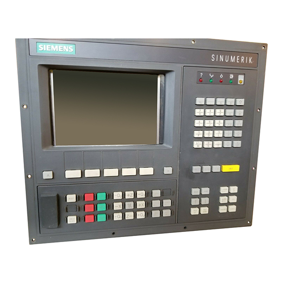
SINUMERIK 810T operator interface with integrated machine control panel ((Foto Nr. 87 E 3834 mittig 1:1 einmontieren)) View of the SINUMERIK 810T, operator interface with integrated machine control panel CRT display with softkeys Editing and input keys (see Section 2.1.1.1) (see Section 2.1.1.4) -
Page 18: Crt Display With Softkeys
2 Operation 09.91 2.1.1 SINUMERIK 810T operator interface with integrated machine control panel 2.1.1.1 CRT display with softkeys Screen edge > CRT display division, text / graphics only within the area of the dotted lines The CRT display is divided into 17 lines, each of 41 characters. The following table shows... - Page 19 09.91 2 Operation 2.1.1 SINUMERIK 810T operator interface with integrated machine control panel TOOL SETTING DATA PART DIAG- COMP. DATA IN-OUT PROGRAM NOSIS > Keys below the CRT display RECALL key for jump back to a higher-level menu in the text display By pressing the RECALL key, you change the softkey functions displayed and return to a higher-level menu.
-
Page 20: Display Panel
2 Operation 09.91 2.1.1 SINUMERIK 810T operator interface with integrated machine control panel 2.1.1.2 Display panel Symbols LED displays View of the display panel “Alarm” display • The red LED lights up whenever there is a signal from the diagnostics monitor. - Page 21 01.93 2 Operation 2.1.1 SINUMERIK 810T operator interface with integrated machine control panel NC-MD Press the ”NC-MD” softkey. Call up MD 272* with this key. Position the cursor on the desired axis 1st axis 272* 2nd axis 3rd axis 4th axis...
- Page 22 2 Operation 09.91 2.1.1 SINUMERIK 810T operator interface with integrated machine control panel “Key assignment” display • The yellow LED is bright: When the lower symbols of all the double-function keys on the Address/numerical keyboard (see Section 2.1.1.3) are active: The lower character of the operated double-function key is shown in the input line (see Section 2.1.1.1).
-
Page 23: Address / Numerical Keys
01.93 2 Operation 2.1.1 SINUMERIK 810T operator interface with integrated machine control panel 2.1.1.3 Address / numerical keys – • View of the address / numerical keys Note: The address/numerical keyboard can be assigned differently by the machine tool manufacturer. - Page 24 2 Operation 09.91 2.1.1 SINUMERIK 810T operator interface with integrated machine control panel Key assignment changeover: With successive operations of this key you make either the upper or lower symbols of the double function keys active. – yellow LED (see Section 2.1.1.2) lit: lower symbols are active –...
- Page 25 09.91 2 Operation 2.1.1 SINUMERIK 810T operator interface with integrated machine control panel Symbol for: ”Multiplication” Address for: ”Angle” A ..Numeral: Address for: ”Feed” F ..Numeral: Address for: ”Tool offset number” D ... Numeral: Address for: ”Subroutine number” L ...
-
Page 26: Editing And Input Keys
2 Operation 11.90 2.1.1 SINUMERIK 810T operator interface with integrated machine control panel 2.1.1.4 Editing and input keys View of editing and input keys Delete input / operator message With this key you delete: • Characters on the input line (see Section 2.1.1.1) –... -
Page 27: Control Keys
11.90 2 Operation 2.1.1 SINUMERIK 810T operator interface with integrated machine control panel 2.1.1.5 Control keys 1...n View of the control keys Cursor left / right movement Cursor up/down movement With these keys you move the cursor on the CRT. - Page 28 2 Operation 11.90 2.1.1 SINUMERIK 810T operator interface with integrated machine control panel With this key you move the cursor • from the start of block to the start of the previous block • to the start of the block in which the cursor is positioned •...
- Page 29 01.93 2 Operation 2.1.1 SINUMERIK 810T operator interface with integrated machine control panel Channel changeover The SINUMERIK 810T has 3 channels: 1...n • By pressing this key once, you change to the next higher channel number compared with the number presently displayed.
- Page 30 2 Operation 09.91 2.1.1 SINUMERIK 810T operator interface with integrated machine control panel Acknowledge alarm With the operation of this key: • you acknowledge the information from the NC diagnostics, displayed on the second line of the CRT display (see Section 2.1.1.1) –...
- Page 31 09.91 2 Operation 2.1.1 SINUMERIK 810T operator interface with integrated machine control panel Diagnostics and start up This switch is intended for: • Start up • Service Please see the Installation Guide. Search for address / block no. / word / calling up data You operate this key when you want to search in a part program for: •...
-
Page 32: Integrated Machine Control Panel
2 Operation 11.90 2.1.1 SINUMERIK 810T operator interface with integrated machine control panel 2.1.1.6 Integrated machine control panel ((Foto-Nr. 810T/..einmontieren)) View of the integrated machine control panel / SINUMERIK 810 T Description of the keys Reset When you operate the ”Reset” key: •... - Page 33 11.90 2 Operation 2.1.1 SINUMERIK 810T operator interface with integrated machine control panel Single block This key enables you to run a part program on a block-by-block basis in the ”AUTOMATIC ” operating mode. When you operate this key, the ”SBL” (Single block) message is dis- played on the first line of the CRT (Section 2.1.1.1).
- Page 34 2 Operation 09.91 2.1.1 SINUMERIK 810T operator interface with integrated machine control panel Example for the use of ”Spindle stop” • during operation in ”MDI AUTOMATIC” mode, a block with a fault is discovered • in ”JOG”, ”INC..”,”REPOS” modes e.g. during repositioning to the contour •...
- Page 35 11.90 2 Operation 2.1.1 SINUMERIK 810T operator interface with integrated machine control panel When you operate the ”Feed start” key: • the feedrate reaches the value specified in the part program. The following values are specified in machine data: - feedrate and rapid traverse speeds...
- Page 36 2 Operation 11.90 2.1.1 SINUMERIK 810T operator interface with integrated machine control panel Continuous mode: When the direction key is pressed (whether you press for a short or long µ time), the axis only traverses one increment (1/ 10/ 100/ 1000/ 10000 depending on the setting).
- Page 37 09.91 2 Operation 2.1.1 SINUMERIK 810T operator interface with integrated machine control panel Key for the selection of operating modes You use this key when you want to select operating modes or further softkey functions. The menu selected is shown on the bottom two lines of the CRT display (menu for softkey functions see Section 2.1.1.1).
- Page 38 2 Operation 09.91 2.1.1 SINUMERIK 810T operator interface with integrated machine control panel Operate the ETC key a second time. A 2nd continuation of the operating mode menu is shown. REF- POINT Section of the CRT display: 2nd extension of the operating mode menu Operate the ETC key a third time.
- Page 39 11.90 2 Operation 2.1.1 SINUMERIK 810T operator interface with integrated machine control panel Feed or rapid traverse override decrease / increase The two keys make it possible for you to decrease or increase the programmed feedrate value ”F” (with reference to 100% value).
- Page 40 09.91 2 Operation 2.1.2 SINUMERIK 810T operator interface with external machine control panel 2-23 © Siemens AG 1990 All Rights Reserved 6ZB5 410-0EP02 SINUMERIK 810T, GA3 (BN)
-
Page 41: Sinumerik 810T Operator Interface With External Machine Control Panel
2 Operation 09.91 2.1.2 SINUMERIK 810T operator interface with external machine control panel 2.1.2 SINUMERIK 810T operator interface with external machine control panel (( Foto - Nr. 87 E 3844 1:1 mittig einmontieren)) View of the SINUMERIK 810 T operator interface with external machine control panel... -
Page 42: External Machine Control Panel
11.90 2 Operation 2.1.2 SINUMERIK 810T operator interface with external machine control panel 2.1.2.1 External machine control panel ((Foto - Nr. 87 E 3840 mittig einmontieren)) View of the external machine control panel Explanation of the operating elements Emergency stop switch... - Page 43 2 Operation 11.90 2.1.2 SINUMERIK 810T operator interface with external machine control panel Operating mode selector switch 1 000 10 000 This rotary switch with 13 latched positions enables you to select the following operating modes: Symbol on the Designation of the...
- Page 44 09.91 2 Operation 2.1.2 SINUMERIK 810T operator interface with external machine control panel Single block switch This key enables you to run a program on a block-by-block basis in the ”AUTOMATIC” operating mode. ” 0 ” When the switch is in position...
- Page 45 01.93 2 Operation 2.1.2 SINUMERIK 810T operator interface with external machine control panel 2-27 © Siemens AG 1990 All Rights Reserved 6ZB5 410-0EP02 SINUMERIK 810T, GA3 (BN)
- Page 46 2 Operation 01.93 2.1.2 SINUMERIK 810T operator interface with external machine control panel Feed / rapid override switch The rotary switch, with 23 latched positions, enables you to decrease or increase the programmed feedrate value ”F” (relative to 100%). The set feedrate value ”F” is displayed on the CRT in %.
- Page 47 09.91 2 Operation 2.1.2 SINUMERIK 810T operator interface with external machine control panel Reset When you operate the ”Reset” key: • The current part program being processed is interrupted. • Diagnostics messages are cleared (Alarm nos. 100 ..2999) •...
- Page 48 2 Operation 09.91 2.1.2 SINUMERIK 810T operator interface with external machine control panel The following values are specified in machine data: - the max. spindle speed - the values for the spindle speed override switch positions. Feed stop/Feed start When you operate the ”Feed stop” key: •...
- Page 49 11.90 2 Operation 2.1.2 SINUMERIK 810T operator interface with external machine control panel Direction keys/traversing axes in ”JOG” mode This key pad enables you to jog the axes in the ”JOG”, ”REPOS” or ”INC...” modes. • The ”Feed stop” LED must not be bright.
- Page 50 2 Operation 11.90 2.1.2 SINUMERIK 810T operator interface with external machine control panel Function of the direction keys With this key you traverse the ”X” axis. – X With this key you traverse the ”X” axis in the opposite direction.
- Page 51 01.93 2 Operation 2.1.2 SINUMERIK 810T operator interface with external machine control panel If you have the TRANSMIT option, you can traverse fictitious axes as well. To be able to traverse the maximum of seven axes which are then available to you, you require a modified M machine control panel.
- Page 52 09.91 2 Operation 2.2 Switching on / off 2-33 © Siemens AG 1990 All Rights Reserved 6ZB5 410-0EP02 SINUMERIK 810T, GA3 (BN)
-
Page 53: Switching On / Off
This is intended to prevent the luminescent layer on the screen from wearing out unnecessarily quickly. If you select a new display during the dark phase of the screen, e.g. by changing mode, the screen is displayed again. 2-34 © Siemens AG 1990 All Rights Reserved 6ZB5 410-0EP02 SINUMERIK 810T, GA3 (BN) -
Page 54: Operating Modes
• Checking and entering the zero offsets • Checking and entering the tool offsets. SINUMERIK 810T offers 7 operating modes enabling you to set the control for the desired operating states. 2.3.2 Operating modes - overview The following different operating modes are available: •... - Page 55 When the reference point has been reached, the position register is set to the value of the reference point coordinates. ”REFPOINT” basic display 2-36 © Siemens AG 1990 All Rights Reserved 6ZB5 410-0EP02 SINUMERIK 810T, GA3 (BN)
- Page 56 When the point of interruption is reached, the ”REPOS offset” display is zero; at the same time the direction keys are no longer active. ”REPOS” basic display 2-37 © Siemens AG 1990 All Rights Reserved 6ZB5 410-0EP02 SINUMERIK 810T, GA3 (BN)
- Page 57 11.90 2 Operation 2.3.3 Selection of operating modes 2-37 © Siemens AG 1990 All Rights Reserved 6ZB5 410-0EP02 SINUMERIK 810T, GA3 (BN)
-
Page 58: Selection Of Operating Modes
MATIC function of each softkey > You operate one of these softkeys. The basic display of the operating mode you selected is shown on the CRT. 2-38 © Siemens AG 1990 All Rights Reserved 6ZB5 410-0EP02 SINUMERIK 810T, GA3 (BN) - Page 59 > You operate one of these softkeys. The basic display for ”INC 1... INC 10 000” mode is shown on the CRT display. 2-39 © Siemens AG 1990 All Rights Reserved 6ZB5 410-0EP02 SINUMERIK 810T, GA3 (BN)
- Page 60 REF- POINT function of the softkey. > You operate this softkey. The basic display for ”REFPOINT” mode is shown on the CRT display. 2-40 © Siemens AG 1990 All Rights Reserved 6ZB5 410-0EP02 SINUMERIK 810T, GA3 (BN)
-
Page 61: Selection Of Operating Modes With External Machine Control Panel
REPOS REPOSITIONING Reposition Reapproach contour (10th position) AUTOMATIC AUTOMATIC OPERATION (11th and 12th position) Execute stored programs REFPOINT TRAVERSE TO Reference Point REFERENCE POINT (13th position) 2-41 © Siemens AG 1990 All Rights Reserved 6ZB5 410-0EP02 SINUMERIK 810T, GA3 (BN) -
Page 62: Reset" With Change Of Operating Mode
When changing from ”AUTOMATIC” to ”JOG” mode, no ”RESET” is generated by the control! When changing from ”JOG” to ”REFPOINT” mode, a ”RESET” is generated by the control! 2-42 © Siemens AG 1990 All Rights Reserved 6ZB5 410-0EP02 SINUMERIK 810T, GA3 (BN) -
Page 63: Branching To Operating Functions Within An Operating Mode
Branching of the operating functions (”Menu tree”) with stylized representation of the menus Note : The detailed branching structure is explained separately for each operating mode in Sections 2.4.1 to 2.4.9. 2-43 © Siemens AG 1990 All Rights Reserved 6ZB5 410-0EP02 SINUMERIK 810T, GA3 (BN) -
Page 64: Example For The Selection Of Operating Functions And Branching To Other Menus
”PART PROGRAM” menu in ”AUTOMATIC” mode is ((Foto - Nr. 810T/12 einmontieren)) shown on the CRT display. The menu shows a branch to 3 new functions. etc. 2-44 © Siemens AG 1990 All Rights Reserved 6ZB5 410-0EP02 SINUMERIK 810T, GA3 (BN) -
Page 65: Example For The Selection Of Further Operating Functions
(DB 40) in the PLC program or a new softkey function (SK 56). The machine tool manufacturer defines which menus can be displayed when. For further details see the relevant User's Guide of the machine tool manufacturer. 2-45 © Siemens AG 1990 All Rights Reserved 6ZB5 410-0EP02 SINUMERIK 810T, GA3 (BN) -
Page 66: Jumping Back To Operating Functions In Higher-Level Menus Within An Operating Mode
If you operate this key once, the next higher-level menu is displayed with functions. Selected MODE Jumping back to higher-level function menus (black arrows), with stylized representation of menus. 2-46 © Siemens AG 1990 All Rights Reserved 6ZB5 410-0EP02 SINUMERIK 810T, GA3 (BN) -
Page 67: Operating Mode Menu Trees
• ”MDI-AUTOMATIC” mode • ”REFPOINT” mode • ”INC FEED 1 ... INC FEED 10000” mode • ”PRESET” mode • ”REPOS” mode • ”GUIDING” (operator prompting) function. 2-47 © Siemens AG 1990 All Rights Reserved 6ZB5 410-0EP02 SINUMERIK 810T, GA3 (BN) -
Page 68: Automatic" Mode
AREA START STOP RESET > PROGRAM BLOCK > GUIDING W-PIECE CONTROL SEARCH function SIMULA- SINGLE SKIP OPT.STP SIMULA- START SIMULA- TION YES-NO YES-NO YES-NO TION TION 2-48 © Siemens AG 1990 All Rights Reserved 6ZB5 410-0EP02 SINUMERIK 810T, GA3 (BN) - Page 69 USER DATA BITS DATA BITS COPY MOVE RENAME DELETE REORG GENERAL AXIAL AXIAL SPINDLE MACH. > DATA DATA 1 DATA 2 DATA BITS CHANNEL > DATA 2-49 © Siemens AG 1990 All Rights Reserved 6ZB5 410-0EP02 SINUMERIK 810T, GA3 (BN)
- Page 70 01.93 2 Operation 2.4.2 ”JOG” mode 2-49 © Siemens AG 1990 All Rights Reserved 6ZB5 410-0EP02 SINUMERIK 810T, GA3 (BN)
-
Page 71: Jog" Mode
AREA START STOP RESET > PROGRAM BLOCK > GUIDING W-PIECE CONTROL SEARCH function SIMULA- SINGLE SKIP OPT.STP SIMULA- START SIMULA- TION YES-NO YES-NO YES-NO TION TION 2-50 © Siemens AG 1990 All Rights Reserved 6ZB5 410-0EP02 SINUMERIK 810T, GA3 (BN) - Page 72 USER DATA BITS DATA BITS GENERAL AXIAL AXIAL SPINDLE MACH. > DATA DATA 1 DATA 2 DATA BITS CHANNEL > COPY MOVE RENAME DELETE REORG DATA 2-51 © Siemens AG 1990 All Rights Reserved 6ZB5 410-0EP02 SINUMERIK 810T, GA3 (BN)
-
Page 73: Jog" Mode (After "Teach In / Playback" In "Automatic" Mode)
VERSION > PARALL SYSTEM SYSTEM USER USER DATA BITS DATA BITS GENERAL AXIAL AXIAL SPINDLE MACH.-> DATA DATA 1 DATA 2 DATA BITS CHANNEL > DATA 2-52 © Siemens AG 1990 All Rights Reserved 6ZB5 410-0EP02 SINUMERIK 810T, GA3 (BN) -
Page 74: Mdi Automatic" Mode
> PARALL SYSTEM SYSTEM USER USER DATA BITS DATA BITS GENERAL AXIAL AXIAL SPINDLE MACH. > CHANNEL > DATA DATA 1 DATA 2 DATA BITS DATA 2-53 © Siemens AG 1990 All Rights Reserved 6ZB5 410-0EP02 SINUMERIK 810T, GA3 (BN) -
Page 75: Refpoint" Mode
AREA START STOP RESET > PROGRAM BLOCK > GUIDING W-PIECE CONTROL SEARCH function SIMULA- SINGLE SKIP OPT.STP SIMULA- START SIMULA- TION YES-NO YES-NO YES-NO TION TION 2-54 © Siemens AG 1990 All Rights Reserved 6ZB5 410-0EP02 SINUMERIK 810T, GA3 (BN) - Page 76 USER USER DATA BITS DATA BITS GENERAL AXIAL AXIAL SPINDLE MACH.-> DATA DATA 1 DATA 2 DATA BITS CHANNEL > COPY MOVE RENAME DELETE REORG DATA 2-55 © Siemens AG 1990 All Rights Reserved 6ZB5 410-0EP02 SINUMERIK 810T, GA3 (BN)
-
Page 77: Inc 1 ... Inc 10 000" Mode
01.93 2 Operation 2.4.6 ”INC 1 ... INC 10 000” mode 2-55 © Siemens AG 1990 All Rights Reserved 6ZB5 410-0EP02 SINUMERIK 810T, GA3 (BN) - Page 78 AREA START STOP RESET > PROGRAM BLOCK > GUIDING W-PIECE CONTROL SEARCH function SIMULA- SINGLE SKIP OPT-STP SIMULA- START SIMULA- TION YES-NO YES-NO YES-NO TION TION 2-56 © Siemens AG 1990 All Rights Reserved 6ZB5 410-0EP02 SINUMERIK 810T, GA3 (BN)
- Page 79 USER DATA BITS DATA BITS GENERAL AXIAL AXIAL SPINDLE MACH. > DATA DATA 1 DATA 2 DATA BITS CHANNEL > DATA COPY MOVE RENAME DELETE REORG 2-57 © Siemens AG 1990 All Rights Reserved 6ZB5 410-0EP02 SINUMERIK 810T, GA3 (BN)
-
Page 80: Preset" Mode
AREA START STOP RESET > PROGRAM BLOCK > GUIDING W-PIECE CONTROL SEARCH function SIMULA- SINGLE SKIP OPT.STP SIMULA- START SIMULA- TION YES-NO YES-NO YES-NO TION TION 2-58 © Siemens AG 1990 All Rights Reserved 6ZB5 410-0EP02 SINUMERIK 810T, GA3 (BN) - Page 81 USER USER DATA BITS DATA BITS GENERAL AXIAL AXIAL SPINDLE MACH.-> DATA DATA 1 DATA 2 DATA BITS CHANNEL > COPY MOVE RENAME DELETE REORG DATA 2-59 © Siemens AG 1990 All Rights Reserved 6ZB5 410-0EP02 SINUMERIK 810T, GA3 (BN)
- Page 82 01.93 2 Operation 2.4.8 ”REPOS” mode 2-59 © Siemens AG 1990 All Rights Reserved 6ZB5 410-0EP02 SINUMERIK 810T, GA3 (BN)
-
Page 83: Repos" Mode
> PARALL SYSTEM SYSTEM USER USER DATA BITS DATA BITS GENERAL AXIAL AXIAL SPINDLE MACH. > CHANNEL > DATA DATA 1 DATA 2 DATA BITS DATA 2-60 © Siemens AG 1990 All Rights Reserved 6ZB5 410-0EP02 SINUMERIK 810T, GA3 (BN) -
Page 84: Guiding" (Operator Prompting) Function
G 347 > G 148 G 248 G 348 G 48 BLOCK > BLOCK G 09 FEED BLOCK G 94 G 95 G 96 G 97 BLOCK 2-61 © Siemens AG 1990 All Rights Reserved 6ZB5 410-0EP02 SINUMERIK 810T, GA3 (BN) - Page 85 ROUGH FINISH ROUGH COMP. EXTERN. EXTERN. INTERN. INTERN. CONTOUR MACHIN TAPER TAPER LONGIT. TRANSV. LONGIT. TRANSV. PITCH EXT. EXTERN INT. INTERN STORE STORE STORE MENU CHOICE 2-62 © Siemens AG 1990 All Rights Reserved 6ZB5 410-0EP02 SINUMERIK 810T, GA3 (BN)
- Page 86 INSIDE LEFT RIGHT LEFT RIGHT THREAD THREAD THREAD RIGHT RIGHT LEFT LEFT EXTERN. INTERN. EXTERN. INTERN. PITCH STORE STORE STORE STORE STORE MENU CHOICE MENU CHOICE 2-63 © Siemens AG 1990 All Rights Reserved 6ZB5 410-0EP02 SINUMERIK 810T, GA3 (BN)
- Page 87 09.91 2 Operation 2.5 Glossary of softkey functions 2-63 © Siemens AG 1990 All Rights Reserved 6ZB5 410-0EP02 SINUMERIK 810T, GA3 (BN)
-
Page 88: Glossary Of Softkey Functions
BTR START (BLOCK TRANSFER) Part programs are loaded into the NC from external storage in sections and executed. CLEAR PRE-OFF (CLEAR PRESET-OFFSET) You clear the PRESET offset. 2-64 © Siemens AG 1990 All Rights Reserved 6ZB5 410-0EP02 SINUMERIK 810T, GA3 (BN) - Page 89 The values required are defined as parameter assignments before the cycles are called (cycle parameter assignment). DATA-IN START (START DATA INPUT) You start data input via the universal interface. 2-65 © Siemens AG 1990 All Rights Reserved 6ZB5 410-0EP02 SINUMERIK 810T, GA3 (BN)
- Page 90 With this function you can select the handwheel assignment. You can assign a handwheel to each defined axis by entering the axis number. DRF YES-NO When ”YES”, the differential resolver function is activated. 2-66 © Siemens AG 1990 All Rights Reserved 6ZB5 410-0EP02 SINUMERIK 810T, GA3 (BN)
-
Page 91: Operating Sequences
LINE You select the G functions for linear interpolation by means of a softkey. 2-67 © Siemens AG 1990 All Rights Reserved 6ZB5 410-0EP02 SINUMERIK 810T, GA3 (BN) - Page 92 With ”YES”, the processing of the program is stopped at the point at which the ”M01” command is programmed. OVERR. YES-NO (FEED / RAPID OVERRIDE ON-OFF) When ”YES”, the set override is valid for the rapid traverse override/feedrate override switch. 2-68 © Siemens AG 1990 All Rights Reserved 6ZB5 410-0EP02 SINUMERIK 810T, GA3 (BN)
- Page 93 Display of two data words – DW Data word – KH Hex constant – KM Binary constant – KF Fixed-point number constant – KS Symbol constant (up to two characters) 2-69 © Siemens AG 1990 All Rights Reserved 6ZB5 410-0EP02 SINUMERIK 810T, GA3 (BN)
- Page 94 Simulation is interrupted and returned to the reset state. ROTAT. ANGLE (ANGLE OF ROTATION) Input of setting data for coordinate system rotation. SCALE MODIF. (SCALE MODIFICATION) Input of setting data for scale modification. 2-70 © Siemens AG 1990 All Rights Reserved 6ZB5 410-0EP02 SINUMERIK 810T, GA3 (BN)
- Page 95 You select G04, G92, M19, G58, G59, G50 and G51 with this softkey. SPECIAL FUNCT. The special functions M00, M01. (1st M Group) and M 36, M37 (4th M Group) are grouped together in this function. 2-71 © Siemens AG 1990 All Rights Reserved 6ZB5 410-0EP02 SINUMERIK 810T, GA3 (BN)
-
Page 96: Store Select
– The stored subroutine numbers – The number of characters used – The free memory space SUBROUT. START (SUBROUTINE START) Activation of output of subroutines via the universal interface. 2-72 © Siemens AG 1990 All Rights Reserved 6ZB5 410-0EP02 SINUMERIK 810T, GA3 (BN) -
Page 97: Tool Data
WORKING AREA LIM. (WORKING AREA LIMITATION) The minimum and maximum working area limits of the defined axes appear in the display. You can modify the values displayed. 2-73 © Siemens AG 1990 All Rights Reserved 6ZB5 410-0EP02 SINUMERIK 810T, GA3 (BN) -
Page 98: Zero Offset
By traversing to the desired reference plane, the zero offset can be measured and stored. ZERO OFFSET The settable zero offsets are input as setting data. Programmable and external zero offsets are displayed on the CRT (see Section 3.1.5). 2-74 © Siemens AG 1990 All Rights Reserved 6ZB5 410-0EP02 SINUMERIK 810T, GA3 (BN) -
Page 99: Preliminary Remarks
In the following subsections, the part of the illustrations shaded grey show the function of the dual function keys required. • In screen forms without an extension (>), the S value for the leading spindle is displayed under S. © Siemens AG 1990 All Rights Reserved 6ZB5 410-0EP02 SINUMERIK 810T, GA3 (BN) -
Page 100: Preparation
REF- POINT You select the ”REFPOINT” operating mode via softkey ...You set the operating mode selector switch on the external machine control panel to this symbol (REFPOINT). © Siemens AG 1990 All Rights Reserved 6ZB5 410-0EP02 SINUMERIK 810T, GA3 (BN) - Page 101 ”ACTUAL POSITION” on the CRT. The control is now synchronized with (( 810T)) the machine. (( Bild 6 von Druckerei einmontieren © Siemens AG 1990 All Rights Reserved 6ZB5 410-0EP02 SINUMERIK 810T, GA3 (BN)
-
Page 102: Tools
Explanation of the input screen form Name of the tool offset memory ( ”D5” in this example). The SINUMERIK 810T has 99 offset memories. You can therefore address the tool offset numbers D1 ... D99, and store offset data under each one. -
Page 103: Tool Number
P1=9 is valid when the cutter P1= 3 P1=4 centre point ”S” is the reference P1= 8 point. © Siemens AG 1990 All Rights Reserved 6ZB5 410-0EP02 SINUMERIK 810T, GA3 (BN) - Page 104 The machine tool manufacturer can set the maximum wear input to ± 0.999 mm. Diameter/radius The input of tool wear data can be inhibited by means of a key switch! © Siemens AG 1990 All Rights Reserved 6ZB5 410-0EP02 SINUMERIK 810T, GA3 (BN)
-
Page 105: Sequence Of Operation
This input screen form appears. The current input field (=the field into which your input will be transferred) is displayed in inverse video (here in the first line). ((Bild 810T/16 einmontieren)) © Siemens AG 1990 All Rights Reserved 6ZB5 410-0EP02 SINUMERIK 810T, GA3 (BN) - Page 106 After storing all the offset values of the selected offset number D..., the inverse video marking of the input field now jumps to the first offset value of the following offset number. © Siemens AG 1990 All Rights Reserved 6ZB5 410-0EP02 SINUMERIK 810T, GA3 (BN)
-
Page 107: Deleting/Modifying An Individual Offset Value
... Using the numerical keys you enter a new value • • • • • • (modification). With this key you transfer the deletion or modification into the offset memory. © Siemens AG 1990 All Rights Reserved 6ZB5 410-0EP02 SINUMERIK 810T, GA3 (BN) - Page 108 11.90 3 Operating Sequences 3.1.4 Tool offset © Siemens AG 1990 All Rights Reserved 6ZB5 410-0EP02 SINUMERIK 810T, GA3 (BN)
-
Page 109: Deleting All Offset Values In An Offset Number D
When you now call the tool offset numbers ”D4” to ”D9”, as described in a) above, you can check that all offset values have been set to ”zero”. 3-10 © Siemens AG 1990 All Rights Reserved 6ZB5 410-0EP02 SINUMERIK 810T, GA3 (BN) -
Page 110: Automatic Tool Offset
AUTOM. TOOL Now operate the ”AUTOMATIC TOOL OFFSET” softkey. This input screen form appears with the input field marked in inverse video. ((Bild 810T/17 einmontieren)) 3-11 © Siemens AG 1990 All Rights Reserved 6ZB5 410-0EP02 SINUMERIK 810T, GA3 (BN) - Page 111 Now store the “Z-axis reference plane” in the same way. • • • The tool offset for the selected axis is automatically calculated and stored in the tool offset memory. 3-12 © Siemens AG 1990 All Rights Reserved 6ZB5 410-0EP02 SINUMERIK 810T, GA3 (BN)
-
Page 112: Integrated Tool Management
Sequence of operation TOOL OFFSET Press the “TOOL OFFSET” softkey. This display then appears on the screen. ((Bild 810T/15 einmontieren)) TOOL DATA Press the “TOOL DATA” softkey. 3-13 © Siemens AG 1990 All Rights Reserved 6ZB5 410-0EP02 SINUMERIK 810T, GA3 (BN) - Page 113 Press the “PAGE UP” or “PAGE DOWN” softkeys to page through the magazine table. PAGE DOWN GEOM. DATA Press the “GEOMETRY DATA” softkey. The input form for tool offset data is displayed again. 3-14 © Siemens AG 1990 All Rights Reserved 6ZB5 410-0EP02 SINUMERIK 810T, GA3 (BN)
-
Page 114: Display Of Tool Data
D No. input is then displayed. Select a D No. and press the search key. The tool D... data under the D No. input is then displayed. 3-15 © Siemens AG 1990 All Rights Reserved 6ZB5 410-0EP02 SINUMERIK 810T, GA3 (BN) - Page 115 Press the “GEOMETRY DATA” softkey to move to the “TOOL OFFSET” menu. You can return to the standard menu by pressing the “RECALL” key twice. 3-16 © Siemens AG 1990 All Rights Reserved 6ZB5 410-0EP02 SINUMERIK 810T, GA3 (BN)
-
Page 116: Zero Offset
Tool setting point Machine zero point Workpiece zero point Machine reference point Slide reference point XMR, ZMR Reference point coordinates Zero offset Tool geometry L1 Tool geometry L2 3-17 © Siemens AG 1990 All Rights Reserved 6ZB5 410-0EP02 SINUMERIK 810T, GA3 (BN) -
Page 117: Settable Zero Offsets
(( Bild 18 von Druckerei einmontieren Press the softkey for the desired G function. The preselected G function is indicated in the display (e.g. G 54). 3-18 © Siemens AG 1990 All Rights Reserved 6ZB5 410-0EP02 SINUMERIK 810T, GA3 (BN) - Page 118 “Fine offset ” for G54 as well. Select the other settable zero offset G55 to G57 using the appropriate softkeys in the menu and proceed as for G54. 3-19 © Siemens AG 1990 All Rights Reserved 6ZB5 410-0EP02 SINUMERIK 810T, GA3 (BN)
-
Page 119: Programmable Zero Offset - External Zero Offset
You can now read the values for “G58” and “G59” for the axes X and Z axes (Q1,Q2,.., if present), but you cannot change them. ((Bild 810T/19 einmontieren)) 3-20 © Siemens AG 1990 All Rights Reserved 6ZB5 410-0EP02 SINUMERIK 810T, GA3 (BN) - Page 120 “G58” and “G59” for the X, Z axes (and Q1,Q2 ... axes,if present), but you cannot change them. ((Bild 810T/20 einmontieren)) The ”External zero offset” is defined via machine data. 3-21 © Siemens AG 1990 All Rights Reserved 6ZB5 410-0EP02 SINUMERIK 810T, GA3 (BN)
-
Page 121: Automatic Calculation Of The Zero Offset
((Bild 810T/21 einmontieren)) Now enter the zero offset number (here ”54”) in the ”G 54 ... G 57” range and terminate your entry using the input key. 3-22 © Siemens AG 1990 All Rights Reserved 6ZB5 410-0EP02 SINUMERIK 810T, GA3 (BN) -
Page 122: Setting Data: "R Parameters", "Spindle", "Axial", "Angle Of Rotation", "Scale Modification
Parameters R 700...R 999 are jointly valid for all channels (central parameters). Only certain R parameters are available for the user. The following overview shows the parameter assignment. 3-23 © Siemens AG 1990 All Rights Reserved 6ZB5 410-0EP02 SINUMERIK 810T, GA3 (BN) - Page 123 09.91 3 Operating Sequences 3.1.6 Setting data: ”R PARAMETERS”, ”SPINDLE”, ”AXIAL”, ”ANGLE OF ROTATION”, ”SCALE MODIFICAT.” 3-23 © Siemens AG 1990 All Rights Reserved 6ZB5 410-0EP02 SINUMERIK 810T, GA3 (BN)
- Page 124 R299 Reserved for internal purposes R300 R300 R300 R499 R499 R499 R500 R500 R500 Additional, channel-specific parameters 810T/M R699 R699 R699 R700 Central parameters 810T/M R999 3-24 © Siemens AG 1990 All Rights Reserved 6ZB5 410-0EP02 SINUMERIK 810T, GA3 (BN)
- Page 125 As long as cycles Transfer program n=00... 90 (Working L 969 are being channel R 11-R 199 <--> Store channel) processed 10 R parameters required: No. is freely selectable. 3-25 © Siemens AG 1990 All Rights Reserved 6ZB5 410-0EP02 SINUMERIK 810T, GA3 (BN)
- Page 126 3 Operating Sequences 09.91 3.1.6 Setting data: ”R PARAMETERS”, ”SPINDLE”, ”AXIAL”, ”ANGLE OF ROTATION”, ”SCALE MODIFICAT.” 3-26 © Siemens AG 1990 All Rights Reserved 6ZB5 410-0EP02 SINUMERIK 810T, GA3 (BN)
- Page 127 ”CH3” (marked in inverse video in the upper right hand corner of the display). Now operate any of the cursor keys to position the cursor to the desired input field of the displayed R parameters. 3-26 © Siemens AG 1990 All Rights Reserved 6ZB5 410-0EP02 SINUMERIK 810T, GA3 (BN)
- Page 128 1) The ”Maximum input value” is fixed in MD. 2) The ”Input unit” is fixed in MD: you can also use 0.1 rev/min instead of rev/min. 3-27 © Siemens AG 1990 All Rights Reserved 6ZB5 410-0EP02 SINUMERIK 810T, GA3 (BN)
- Page 129 Enter the value for the selected input field with the numeric keys. Subsequently, you can transfer the value into the • • • input field with the input key. 3-28 © Siemens AG 1990 All Rights Reserved 6ZB5 410-0EP02 SINUMERIK 810T, GA3 (BN)
- Page 130 Operate the ”SETTING DATA” softkey in any operating mode. Extend the softkey menu displayed using the ETC key to the right below the display. AXIAL Operate the ”AXIAL” softkey. 3-29 © Siemens AG 1990 All Rights Reserved 6ZB5 410-0EP02 SINUMERIK 810T, GA3 (BN)
- Page 131 ((Bild 810T/25 einmontieren)) You can assign each of up to seven axes (for the TRANSMIT function) to a handwheel. 3-30 © Siemens AG 1990 All Rights Reserved 6ZB5 410-0EP02 SINUMERIK 810T, GA3 (BN)
- Page 132 A... for G58 and G59 are defaulted by the program and only displayed in the screen form). Then proceed as follows: With the cursor keys, position the cursor at the desired input field (G54 ... G57). 3-31 © Siemens AG 1990 All Rights Reserved 6ZB5 410-0EP02 SINUMERIK 810T, GA3 (BN)
- Page 133 – Channel 3 : P ... • The “scale centre” (reference point) : – Axis 1 : X ... – Axis 2 : Z ... 3-32 © Siemens AG 1990 All Rights Reserved 6ZB5 410-0EP02 SINUMERIK 810T, GA3 (BN)
-
Page 134: Flexible Plane Selection
All designations must have been defined by the machine manufacturer in the appropriate NC MD 548*, 550*, 552* and 304*. 3-33 © Siemens AG 1990 All Rights Reserved 6ZB5 410-0EP02 SINUMERIK 810T, GA3 (BN) - Page 135 Example: standard plane G18 for turning or G17 for drilling. How this basic setting is defined is described in Section 7.3.4 “Definition of the initial setting of the G groups”. 3-34 © Siemens AG 1990 All Rights Reserved 6ZB5 410-0EP02 SINUMERIK 810T, GA3 (BN)
-
Page 136: Axis Synchronization
In these modes the offsets which have arisen between the leading and the following axis after “Block search” or “AUTOMATIC interrupted” etc. can be eliminated in various ways: 3-35 © Siemens AG 1990 All Rights Reserved 6ZB5 410-0EP02 SINUMERIK 810T, GA3 (BN) - Page 137 If “axis synchronization” is selected, the following axis is always traversed together with the leading axis (tool system 1), as long as the movements are programmed! 3-36 © Siemens AG 1990 All Rights Reserved 6ZB5 410-0EP02 SINUMERIK 810T, GA3 (BN)
-
Page 138: Transmit Coordinate Transformation
For further details, consult the machine manufacturer's instructions. Exception: The TRANSMIT function is always deselected by the change to the “REFPOINT” mode (reference point approach). 3-37 © Siemens AG 1990 All Rights Reserved 6ZB5 410-0EP02 SINUMERIK 810T, GA3 (BN) - Page 139 “JOG” (AUTOMATIC interrupted) state: The program was interrupted and the “JOG” state selected. – “AUTOMATIC interrupted” state: The programm was interrupted, without leaving the “AUTOMATIC” mode (NC Stop). 3-38 © Siemens AG 1990 All Rights Reserved 6ZB5 410-0EP02 SINUMERIK 810T, GA3 (BN)
-
Page 140: Transmit Function In The Various Modes
Reference points therefore only exist for real axes and not for fictitious axes. “REPOS” mode: After “block search” or “AUTOMATIC interrupted” the contour can only be approached in the previously selected coordinate system. 3-39 © Siemens AG 1990 All Rights Reserved 6ZB5 410-0EP02 SINUMERIK 810T, GA3 (BN) - Page 141 During follow-up mode for real axes, the values for the fictitious axes are not prepared. Data preparation in the NC begins with the changeover of the axes from follow-up mode to closed- loop control. 3-40 © Siemens AG 1990 All Rights Reserved 6ZB5 410-0EP02 SINUMERIK 810T, GA3 (BN)
-
Page 142: Monitoring The Software Limit Switch For Fictitious Axes With The Transmit Function
(i.e. you have moved the axes back into the normal working area in JOG or INC mode). 3-41 © Siemens AG 1990 All Rights Reserved 6ZB5 410-0EP02 SINUMERIK 810T, GA3 (BN) -
Page 143: Program Input
Apart from program input, the PART PROGRAM function also serves for: – Program editing (see Section 3.1.12) – Program management (see Section 3.1.13) – Program simulation (see Section 3.1.14). 3-42 © Siemens AG 1990 All Rights Reserved 6ZB5 410-0EP02 SINUMERIK 810T, GA3 (BN) - Page 144 Operate the ”SELECT PROGRAM ” softkey. You can now either input a new program or modify a part program already in the control using the input screen form displayed. 3-43 © Siemens AG 1990 All Rights Reserved 6ZB5 410-0EP02 SINUMERIK 810T, GA3 (BN)
- Page 145 With this key you can modify either the complete block or a single word before which the cursor is positioned. 3-44 © Siemens AG 1990 All Rights Reserved 6ZB5 410-0EP02 SINUMERIK 810T, GA3 (BN)
-
Page 146: Contour
”Extend softkey menu” key (ETC) BLOCK G FUNC- LINE CIRCLE THREAD NUMBER TIONS CONTOUR WORK FEED SPINDLE TOOL CYCLE SPECIAL SPECIAL PROGR. BLOCK ADD. BLOCK FUNCT. FUNCT. 3-45 © Siemens AG 1990 All Rights Reserved 6ZB5 410-0EP02 SINUMERIK 810T, GA3 (BN) - Page 147 Apart from program input, the PART PROGRAM function also serves for – Program editing (see Section 3.1.12) – Program management (see Section 3.1.13) – Program simulation (see Section 3.1.14). 3-46 © Siemens AG 1990 All Rights Reserved 6ZB5 410-0EP02 SINUMERIK 810T, GA3 (BN)
- Page 148 The block numbers are generated by the control in steps of 5, i.e. after each LF (end of block) the block number is incremented by ”5”. 3-47 © Siemens AG 1990 All Rights Reserved 6ZB5 410-0EP02 SINUMERIK 810T, GA3 (BN)
- Page 149 Operate this key to return to a higher-level softkey menu. LINE With the ”LINE”softkey, select ”Linear interpolation”. By operating the ”G00” softkey, select the ”Rapid traverse” function. “G00” is displayed. 3-48 © Siemens AG 1990 All Rights Reserved 6ZB5 410-0EP02 SINUMERIK 810T, GA3 (BN)
- Page 150 The control generates the next number, ”5” higher. ”N0010” is displayed and created in the program. etc. etc. Continue with input until you have completed the part program. 3-49 © Siemens AG 1990 All Rights Reserved 6ZB5 410-0EP02 SINUMERIK 810T, GA3 (BN)
-
Page 151: Contour
REFPOINT PART PROGRAM Now operate the ”PART PROGRAM” softkey. EDIT Operate the ”EDIT” softkey. Use the numerical keys to enter the desired program no. %..3-50 © Siemens AG 1990 All Rights Reserved 6ZB5 410-0EP02 SINUMERIK 810T, GA3 (BN) - Page 152 • • • spindle S... using the numerical keys and store them using the input key. • • • Extend the softkey menu. CONTOUR Select the ”CONTOUR” softkey. 3-51 © Siemens AG 1990 All Rights Reserved 6ZB5 410-0EP02 SINUMERIK 810T, GA3 (BN)
- Page 153 ”LINE-CIRCLE” function using a softkey. This input screen form appears with the input field marked in inverse video. The contour element selected is displayed graphically. ((Bild 810T/29 einmontieren)) 3-52 © Siemens AG 1990 All Rights Reserved 6ZB5 410-0EP02 SINUMERIK 810T, GA3 (BN)
- Page 154 The contour definition is now stored in the part program with all the entered values. The control generates the ”Block end” (LF) character itself, and shows you the complete block entered. 3-53 © Siemens AG 1990 All Rights Reserved 6ZB5 410-0EP02 SINUMERIK 810T, GA3 (BN)
- Page 155 11.90 3 Operating Sequences 3.1.12 Program correction (”EDIT”): Insert/modify/delete word, insert/delete block 3-53 © Siemens AG 1990 All Rights Reserved 6ZB5 410-0EP02 SINUMERIK 810T, GA3 (BN)
-
Page 156: Program Correction ("Edit"): Insert/Modify/Delete Word, Insert/Delete Block
Call the desired program using ”PROGRAM SELECT”. You can now either modify a stored part program or enter a new program in the displayed screen form. 3-54 © Siemens AG 1990 All Rights Reserved 6ZB5 410-0EP02 SINUMERIK 810T, GA3 (BN) - Page 157 Position the cursor in front of the ....block which will follow the inserted block (in the example a new block will be inserted in front of block ”N5”). 3-55 © Siemens AG 1990 All Rights Reserved 6ZB5 410-0EP02 SINUMERIK 810T, GA3 (BN)
- Page 158 (in the example, preparatory function”G..”) Using the numerical keys enter ”N0” (0=zero) and then operate the ”Delete word/block” key. 3-56 © Siemens AG 1990 All Rights Reserved 6ZB5 410-0EP02 SINUMERIK 810T, GA3 (BN)
-
Page 159: Correction Display ("Correction Block")
(address ”X” in the example) and enter the appropriate value, • • • subsequently operate the ”Modify word” key. After the correction operate the “Program start” key to continue program progressing. 3-57 © Siemens AG 1990 All Rights Reserved 6ZB5 410-0EP02 SINUMERIK 810T, GA3 (BN) -
Page 160: Program Management
ROUT. The displays of the directories for: ”SUBROUTINE” or ”CYCLES” are selected using the softkey menu on the CRT. ”Page up/down” is possible as described previously. 3-58 © Siemens AG 1990 All Rights Reserved 6ZB5 410-0EP02 SINUMERIK 810T, GA3 (BN) -
Page 161: Protection Of Subroutines (Cycle Lock)
• • • LOCK Now operate the ”LOCK” softkey. The protected subroutine is entered in the cycle list. Cycles are protected subroutines. 3-59 © Siemens AG 1990 All Rights Reserved 6ZB5 410-0EP02 SINUMERIK 810T, GA3 (BN) -
Page 162: Cycle Lock Release ("Enable")
PLC accordingly. This effectively protects the machine tool manufacturer's or user's knowhow. It is then no longer possible for the operator to enable and disable programs! 3-60 © Siemens AG 1990 All Rights Reserved 6ZB5 410-0EP02 SINUMERIK 810T, GA3 (BN) -
Page 163: Copying A Program ("Copy")
” % 88 = % 5 ”. COPY Now operate the ”COPY” softkey. The control now copies program ”%88” and stores a copy it under program number ”%5”. Program ”%88” remains unchanged. 3-61 © Siemens AG 1990 All Rights Reserved 6ZB5 410-0EP02 SINUMERIK 810T, GA3 (BN) -
Page 164: Moving A Program ("Move")
The cycle in the EPROM can be called again with the ”SELECT PROGRAM” softkey, when the respective cycle has been deleted from the program memory. 3-62 © Siemens AG 1990 All Rights Reserved 6ZB5 410-0EP02 SINUMERIK 810T, GA3 (BN) -
Page 165: Renaming A Program ("Rename")
The (former) program ”%2” now has the number ”%5”. The “RENAME” and “DELETE” softkeys are positioned next to each other! A program could be inadvertently deleted through an operating error if you press “DELETE”. 3-63 © Siemens AG 1990 All Rights Reserved 6ZB5 410-0EP02 SINUMERIK 810T, GA3 (BN) - Page 166 11.90 3 Operating Sequences 3.1.13 Program management 3-63 © Siemens AG 1990 All Rights Reserved 6ZB5 410-0EP02 SINUMERIK 810T, GA3 (BN)
-
Page 167: Deleting A Program ("Delete")
All programs from ”% 2” to ”% 5” inclusive, are now deleted by the control. Note: The memory space cleared by deletion of the programs will become available again only after ”REORG” (see Section 3.1.13.8). 3-64 © Siemens AG 1990 All Rights Reserved 6ZB5 410-0EP02 SINUMERIK 810T, GA3 (BN) -
Page 168: Reorganizing The Program Memory ("Reorg")
11 characters multiplied by the number of possible programs (max. 200) in program memory. The number of possible programs is fixed in a machine data. 3-65 © Siemens AG 1990 All Rights Reserved 6ZB5 410-0EP02 SINUMERIK 810T, GA3 (BN) -
Page 169: Selecting A Program
N0005 to N ..Using the ”Page up/down” keys, you can call up the parts of the program not yet displayed (if already in memory) onto the CRT. 3-66 © Siemens AG 1990 All Rights Reserved 6ZB5 410-0EP02 SINUMERIK 810T, GA3 (BN) -
Page 170: Operator Guidance Macros (Ogm) And Back Translation
The OGM number is between 1 and 998. %BFM 999 contains a cross-reference list of all OGMs. e.g. %BFM 999 Grooving 7,34 <Name> = <OGM No.>, <MB No.> Dressing 8,35 MB=menu block 3-67 © Siemens AG 1990 All Rights Reserved 6ZB5 410-0EP02 SINUMERIK 810T, GA3 (BN) - Page 171 The plane selection must be compatible with the following contour definition. I.e. if the plane selection has been changed using the function EDIT, back translation of the data block might not be possible. 3-68 © Siemens AG 1990 All Rights Reserved 6ZB5 410-0EP02 SINUMERIK 810T, GA3 (BN)
- Page 172 %BFM 7 (OGM:grooving) N 100 N10 L F @ccc (X:Y:Z) R11 = R11 = 123 L F R12 = R12 = 24 L F (OGM: grooving) 3-69 © Siemens AG 1990 All Rights Reserved 6ZB5 410-0EP02 SINUMERIK 810T, GA3 (BN)
- Page 173 (BLOCK in the example). STORE Data transfer into the program block DELETE BLOCK With this key, you can delete the data block with the preselected number. 3-70 © Siemens AG 1990 All Rights Reserved 6ZB5 410-0EP02 SINUMERIK 810T, GA3 (BN)
- Page 174 ... . The program number entered is preselected in the display for part program editing (EDIT). 3-71 © Siemens AG 1990 All Rights Reserved 6ZB5 410-0EP02 SINUMERIK 810T, GA3 (BN)
-
Page 175: Simulation
PRESET / JOG / AUTOMATIC / INC FEED 1 ..INC FEED 10 000 / REFPOINT, operate the ”PART PROGRAM” and ”EDIT” softkeys one after the other. 3-72 © Siemens AG 1990 All Rights Reserved 6ZB5 410-0EP02 SINUMERIK 810T, GA3 (BN) - Page 176 ”Simulation area” into the input fields. Terminate each input with the input key. After each input, the inverse video marking jumps to the next input field. 3-73 © Siemens AG 1990 All Rights Reserved 6ZB5 410-0EP02 SINUMERIK 810T, GA3 (BN)
-
Page 177: Influencing Simulation
PRESET / JOG / AUTOMATIC / INC FEED 1 ..INC FEED 10 000 / REFPOINT. 3-74 © Siemens AG 1990 All Rights Reserved 6ZB5 410-0EP02 SINUMERIK 810T, GA3 (BN) - Page 178 ”YES”. ((Bild 810T/33 einmontieren)) SIMULA- TION Now operate the ”SIMULATION” softkey again, and then operate the ETC key to extend the displayed softkey menu. 3-75 © Siemens AG 1990 All Rights Reserved 6ZB5 410-0EP02 SINUMERIK 810T, GA3 (BN)
- Page 179 TION Operate the “SIMULATION” softkey and then the ETC key to extend the softkey menu. This brings you back to the softkey menu for influencing simulation. 3-76 © Siemens AG 1990 All Rights Reserved 6ZB5 410-0EP02 SINUMERIK 810T, GA3 (BN)
-
Page 180: Data Input/Data Output
”SETTING DATA” function. Modification of the interface data - especially for interface no. 1 - is necessary for example, when a different device is interfaced to the SINUMERIK 810T (punch, tape reader, program- mer, etc.) You will find the necessary information for setting/modifying the setting data bits in Section 3.1.15.1 (Setting data bits) and Section 6.3 (Assignment of the setting data for the connection... -
Page 181: Setting Data Bits
Operate the ”SETTING DATA” softkey in any of the operating modes. Using the ETC key, extend the displayed softkey menu. SETTING BITS Using the softkey, select the ”SETTING BITS” function. 3-78 © Siemens AG 1990 All Rights Reserved 6ZB5 410-0EP02 SINUMERIK 810T, GA3 (BN) - Page 182 • • • Leading zeros in the bit combination can be omitted. Carry on in this way until all the required setting data have been set. 3-79 © Siemens AG 1990 All Rights Reserved 6ZB5 410-0EP02 SINUMERIK 810T, GA3 (BN)
-
Page 183: Data Input
On the Data type: line the data coming from the transmission device (tape reader, programmer ...) is identified. The following table explains the types of data that can be loaded into the 810T: 3-80 © Siemens AG 1990 All Rights Reserved 6ZB5 410-0EP02 SINUMERIK 810T, GA3 (BN) - Page 184 Using the ”STOP” softkey, you can interrupt data input at any time. DATA-IN START You continue data input again. During data input it is not possible for the control to call up specific data! 3-81 © Siemens AG 1990 All Rights Reserved 6ZB5 410-0EP02 SINUMERIK 810T, GA3 (BN)
-
Page 185: Data Output
”2” ( for output via Interface 2 ) and store it using the input key. PART PROGRAM Using the softkey, now select, for example, the ”PART PROGRAM” function. 3-82 © Siemens AG 1990 All Rights Reserved 6ZB5 410-0EP02 SINUMERIK 810T, GA3 (BN) - Page 186 Now store your input with the input key. MAINPRG. SUBROUT. START START Operate the ”MAIN PROGRAM START” or ”SUBROUTINE START” softkey. By doing this, you start the control's transmit function (output of data). 3-83 © Siemens AG 1990 All Rights Reserved 6ZB5 410-0EP02 SINUMERIK 810T, GA3 (BN)
- Page 187 Using the ETC key you can extend the displayed softkey menu. The displayed function gives you the possibility to output R PARA- all the ”R parameters”. METER R PARA- METER Operate the ”R parameter” softkey. 3-84 © Siemens AG 1990 All Rights Reserved 6ZB5 410-0EP02 SINUMERIK 810T, GA3 (BN)
- Page 188 The input of a channel no. is only required by the control for ”R PARAMETERS”. • Data output with or without leader or trailer can be set via setting data (SD 5016, bit 1). 3-85 © Siemens AG 1990 All Rights Reserved 6ZB5 410-0EP02 SINUMERIK 810T, GA3 (BN)
-
Page 189: Part Program - Block Transfer
If you have entered 0 as program number in the AUTOMATIC basic display, the incoming program number will not be checked. This enables you to read in a program of which you do not know the program number. 3-86 © Siemens AG 1990 All Rights Reserved 6ZB5 410-0EP02 SINUMERIK 810T, GA3 (BN) - Page 190 Should you require more detailed information on data transmission, please refer to the “Installation Instructions.” 3-87 © Siemens AG 1990 All Rights Reserved 6ZB5 410-0EP02 SINUMERIK 810T, GA3 (BN)
-
Page 191: Nc In Two Languages
"Software version display" with an arrow (>). You can select the "Software version display" via the softkeys DIAGNOSIS and SW VERSION. The language selection is made in the machine data. 3-88 © Siemens AG 1990 All Rights Reserved 6ZB5 410-0EP02 SINUMERIK 810T, GA3 (BN) -
Page 192: Machining
´acturer. The red ”Feed hold” LED display will then be extinguished. After the program start, either ”CURRENT VALUES” or ”CURRENT BLOCK” appear on the CRT display. 3-89 © Siemens AG 1990 All Rights Reserved 6ZB5 410-0EP02 SINUMERIK 810T, GA3 (BN) -
Page 193: Automatic" Operating Mode - Selection Of The "Current Values" Or "Current Block" Display
CRT - in the example, for the program ”%88”. (( 810T)) (( Bild 3 von Druckerei einmontieren You can extend the displayed softkey menu with this key. 3-90 © Siemens AG 1990 All Rights Reserved 6ZB5 410-0EP02 SINUMERIK 810T, GA3 (BN) - Page 194 Actual pos. Distance to go X..... X....Z..... Z....Actual position and distance-to-go value of the axes. Q1..Q1.... Q2..Q2.... Q3..Q3.... 3-91 © Siemens AG 1990 All Rights Reserved 6ZB5 410-0EP02 SINUMERIK 810T, GA3 (BN)
- Page 195 Likewise, a block before or after the ”current block” with more than 41 characters is not displayed. User generated cycles are still displayed under “CURRENT BLOCK” after a cycle disable. 3-92 © Siemens AG 1990 All Rights Reserved 6ZB5 410-0EP02 SINUMERIK 810T, GA3 (BN)
-
Page 196: Influencing "Automatic" Operation
HOLD: DWELL TIME Processing of the program is interrupted for the duration of the programmed dwell time. Note: ”Feed hold” is not displayed on the CRT! 3-93 © Siemens AG 1990 All Rights Reserved 6ZB5 410-0EP02 SINUMERIK 810T, GA3 (BN) -
Page 197: Influencing The Program
You select, for example, the ”SKIP BLOCK” softkey function . Display: Skip block Blocks in the program which are marked with an oblique before the block number (”/ N ...”) are skipped. 3-94 © Siemens AG 1990 All Rights Reserved 6ZB5 410-0EP02 SINUMERIK 810T, GA3 (BN) - Page 198 ”NO”, this override switch is only active with ”feedrate”. If the softkey function is set to ”YES”, the override set with this override switch is also effective for rapid traverse. 3-95 © Siemens AG 1990 All Rights Reserved 6ZB5 410-0EP02 SINUMERIK 810T, GA3 (BN)
- Page 199 Now operate the ”Program start” key. The decoding single block is now processed. Operate the ”Program start” key once more. The next decoding single block is processed ... etc. 3-96 © Siemens AG 1990 All Rights Reserved 6ZB5 410-0EP02 SINUMERIK 810T, GA3 (BN)
- Page 200 - that have not yet been processed - cannot be stopped. • A ”Decoding single block” can be influenced using ”OVERSTORE” (see Section 3.2.3.2). 3-97 © Siemens AG 1990 All Rights Reserved 6ZB5 410-0EP02 SINUMERIK 810T, GA3 (BN)
- Page 201 09.91 3 Operating Sequences 3.2.3 Influencing ”AUTOMATIC” operation 3-97 © Siemens AG 1990 All Rights Reserved 6ZB5 410-0EP02 SINUMERIK 810T, GA3 (BN)
- Page 202 It is always only possible to activate one axis with one handwheel. If a second axis is selected, the previously selected axis is automatically deactivated (see Section 3.2.9 “HANDWHEEL” and Section 3.2.10 “DRF” for further details). 3-98 © Siemens AG 1990 All Rights Reserved 6ZB5 410-0EP02 SINUMERIK 810T, GA3 (BN)
-
Page 203: Overstore
Extend the displayed softkey menu and operate the ”OVERSTORE” softkey . This input form appears with the input field marked in inverse video. (( 810T)) (( Bild 46 von Druckerei einmontieren 3-99 © Siemens AG 1990 All Rights Reserved 6ZB5 410-0EP02 SINUMERIK 810T, GA3 (BN) - Page 204 The program now operates with these new values until a new value in the program supersed- es the overstored function, or until you enter a new value using ”OVERSTORE”. 3-100 © Siemens AG 1990 All Rights Reserved 6ZB5 410-0EP02 SINUMERIK 810T, GA3 (BN)
-
Page 205: Block Search
... set the operating mode selector switch on the external machine control panel to this symbol. BLOCK SEARCH Extend the displayed softkey menu, and subsequently select the ”BLOCK SEARCH” softkey function . 3-101 © Siemens AG 1990 All Rights Reserved 6ZB5 410-0EP02 SINUMERIK 810T, GA3 (BN) - Page 206 Block search in the L95/96 cycles: if comment texts are in the contour program without block numbers, the control outputs the alarm 3000 “General programming error”. 3-102 © Siemens AG 1990 All Rights Reserved 6ZB5 410-0EP02 SINUMERIK 810T, GA3 (BN)
- Page 207 Now switch again into the ”AUTOMATIC” mode, using either the softkey or the operating mode selector switch. Program processing continues after you have pressed the “NC start” key. 3-103 © Siemens AG 1990 All Rights Reserved 6ZB5 410-0EP02 SINUMERIK 810T, GA3 (BN)
-
Page 208: Interrupting The Program
Now operate the ”NC Start” and ”Feed start” keys. The feed is enabled again. The axis positions programmed in the current block are approached with linear interpolation. Caution: danger of collision!! 3-104 © Siemens AG 1990 All Rights Reserved 6ZB5 410-0EP02 SINUMERIK 810T, GA3 (BN) -
Page 209: Program Sequencing (Ops)
You are in the AUTOMATIC mode. AUTOMATIC Having expanded the softkey menu you operate the "OPS" softkey. This display appears on the screen. (( 810T)) (( Bild 49 von Druckerei einmontieren 3-105 © Siemens AG 1990 All Rights Reserved 6ZB5 410-0EP02 SINUMERIK 810T, GA3 (BN) - Page 210 09.91 3 Operating Sequences 3.2.3 Influencing ”AUTOMATIC” operation 3-105 © Siemens AG 1990 All Rights Reserved 6ZB5 410-0EP02 SINUMERIK 810T, GA3 (BN)
- Page 211 Example: File = 10 The file NC-0010 is opened on diskette, the %10 main program is transferred from the NC part program memory into this file. 3-106 © Siemens AG 1990 All Rights Reserved 6ZB5 410-0EP02 SINUMERIK 810T, GA3 (BN)
- Page 212 NC memory. You only have to enter the file number. The main program of this file and all subroutines that may have been added to this file are transferred. 3-107 © Siemens AG 1990 All Rights Reserved 6ZB5 410-0EP02 SINUMERIK 810T, GA3 (BN)
- Page 213 You enter the number of main programs which are to be processed in OPS into the screen form, together with their respective number of units (=number of runs). You use the cursor keys to move the cursor. 3-108 © Siemens AG 1990 All Rights Reserved 6ZB5 410-0EP02 SINUMERIK 810T, GA3 (BN)
- Page 214 NC memory is prior to this cleared except for a reserved range of program numbers (the limits of this range can be set at the disk drive unit). 3-109 © Siemens AG 1990 All Rights Reserved 6ZB5 410-0EP02 SINUMERIK 810T, GA3 (BN)
- Page 215 You operate the “RUN OPS” softkey. The display below appears on the screen. You can now start, monitor and interrupt program sequencing. (( 810T)) (( Bild 50 von Druckerei einmontieren 3-110 © Siemens AG 1990 All Rights Reserved 6ZB5 410-0EP02 SINUMERIK 810T, GA3 (BN)
- Page 216 If the consecutive number and the remaining quantity are both changed at the same time, only the new consecutive number will be taken into account! 3-111 © Siemens AG 1990 All Rights Reserved 6ZB5 410-0EP02 SINUMERIK 810T, GA3 (BN)
- Page 217 ("Different programs same No. (RS232C (V.24))") if the incompletely transferred file is once again called from there. For further details, please refer to the documents on the DSG-2S disk drive. 3-112 © Siemens AG 1990 All Rights Reserved 6ZB5 410-0EP02 SINUMERIK 810T, GA3 (BN)
- Page 218 UMS data ” A S M xx” PLC program ” P C P xx” (xx are any two characters which no longer belong to the header) 3-113 © Siemens AG 1990 All Rights Reserved 6ZB5 410-0EP02 SINUMERIK 810T, GA3 (BN)
-
Page 219: Manual Data Input - Automatic" (Mdi Automatic) Mode
Using the numerical keyboard enter a block following the guidelines in the Programming Instructions, and terminate each input in- cluding ”LF” (end of block) using the input key. 3-114 © Siemens AG 1990 All Rights Reserved 6ZB5 410-0EP02 SINUMERIK 810T, GA3 (BN) - Page 220 Before ”Program start” is operated, you can enter several blocks (max. 256 characters). The ”retentive (modal) input data” (feedrate) remain. They are deleted or reset • by changing the operating mode • by ”RESET” 3-115 © Siemens AG 1990 All Rights Reserved 6ZB5 410-0EP02 SINUMERIK 810T, GA3 (BN)
- Page 221 11.90 3 Operating Sequences 3.2.5 ”TEACH IN” 3-115 © Siemens AG 1990 All Rights Reserved 6ZB5 410-0EP02 SINUMERIK 810T, GA3 (BN)
-
Page 222: Teach In
(end of block) - with the input key. Note : You can also work with operator - ”GUIDING” (see Section 3.1.10.2). The part program is entered directly into the part program memory. 3-116 © Siemens AG 1990 All Rights Reserved 6ZB5 410-0EP02 SINUMERIK 810T, GA3 (BN) -
Page 223: Playback
Set the mode selector switch on the external machine control panel to one of the following symbols: INC ... 1, 10, 100, 1 000, 10 000 3-117 © Siemens AG 1990 All Rights Reserved 6ZB5 410-0EP02 SINUMERIK 810T, GA3 (BN) - Page 224 ”F...” etc., and terminate each input including ”LF” (block end) with the input key. Note: You cannot work with operator ”GUIDING”. 3-118 © Siemens AG 1990 All Rights Reserved 6ZB5 410-0EP02 SINUMERIK 810T, GA3 (BN)
- Page 225 PART TEACH IN PROGRAM PL.BACK Then operate the ”PART PROGRAM” softkey followed by the ”TEACH IN / PLAYBACK” softkey. 3-119 © Siemens AG 1990 All Rights Reserved 6ZB5 410-0EP02 SINUMERIK 810T, GA3 (BN)
- Page 226 Continue as described above under “Sequence of operation”. Note: When you have set up the desired program, terminate it with M02 L or M30 L 3-120 © Siemens AG 1990 All Rights Reserved 6ZB5 410-0EP02 SINUMERIK 810T, GA3 (BN)
-
Page 227: Jog" Mode
You can traverse a maximum of 2 axes at the same time. – Q – X The red ”Feed hold” LED display, must not be bright during the sequence of operation. 3-121 © Siemens AG 1990 All Rights Reserved 6ZB5 410-0EP02 SINUMERIK 810T, GA3 (BN) -
Page 228: Incremental" Mode ("Inc Feed 1
The weighting of the increments depends on the display resolution. However, the smallest possible traversing distance is defined by the input resolution. The feedrate, the input resolution and the display resolution are defined in the machine data. 3-122 © Siemens AG 1990 All Rights Reserved 6ZB5 410-0EP02 SINUMERIK 810T, GA3 (BN) - Page 229 When ”Modal” the axis is always traversed by one increment, in accordance with the setting (1, 10, 100, 1000, 10 000 increments), when the key is pressed (irrespective of whether the key is pressed for a short or long time). 3-123 © Siemens AG 1990 All Rights Reserved 6ZB5 410-0EP02 SINUMERIK 810T, GA3 (BN)
-
Page 230: Handwheel
” 1 ”, ” 10 ”, ” 100 ”, ” 1000 ”or ” 10 000 ” setting (”10” in example). 3-124 © Siemens AG 1990 All Rights Reserved 6ZB5 410-0EP02 SINUMERIK 810T, GA3 (BN) - Page 231 On the display, the enable for the other axes automa- tically changes to “NO”, i.e. the axis is blocked for the handwheel. 3-125 © Siemens AG 1990 All Rights Reserved 6ZB5 410-0EP02 SINUMERIK 810T, GA3 (BN)
- Page 232 09.91 3 Operating Sequences 3.2.10 “DRF” 3-125 © Siemens AG 1990 All Rights Reserved 6ZB5 410-0EP02 SINUMERIK 810T, GA3 (BN)
-
Page 233: Drf
ETC key. PROGRAM CONTROL Operate the ”PROGRAM CONTROL” softkey, and then extend the displayed softkey menu. This CRT display appears. (( 810T)) (( Bild52 von Druckerei einmontieren 3-126 © Siemens AG 1990 All Rights Reserved 6ZB5 410-0EP02 SINUMERIK 810T, GA3 (BN) - Page 234 On the display, the enable for the other axes automati- cally changes to “NO”, i.e. the axis is blocked for the handwheel. 3-127 © Siemens AG 1990 All Rights Reserved 6ZB5 410-0EP02 SINUMERIK 810T, GA3 (BN)
-
Page 235: Actual Value Setting" Mode ("Preset")
– after ”End of Program” – after ”RESET” Machine data defines whether the PRESET offset is automatically deleted ; by switching on the control by traversing to reference point 3-128 © Siemens AG 1990 All Rights Reserved 6ZB5 410-0EP02 SINUMERIK 810T, GA3 (BN) - Page 236 ”X” for the X axis. Then assign this axis the corresponding value of the ”PRESET offset” using the numerical keys and finally operate the ”STORE” softkey. 3-129 © Siemens AG 1990 All Rights Reserved 6ZB5 410-0EP02 SINUMERIK 810T, GA3 (BN)
- Page 237 – the entered value – plus: the calculated tool offset. CLEAR PRE-OFF You can clear all the ”PRESET offsets” at once by operating the ”CLEAR PRESET- OFFSET” softkey. 3-130 © Siemens AG 1990 All Rights Reserved 6ZB5 410-0EP02 SINUMERIK 810T, GA3 (BN)
-
Page 238: Repositioning" Mode ("Repos")
After a tool change, ”REPOS” mode can only be used with the same tool dimensions as before! Otherwise you use: – the ”Block search” method (see Section 3.2.3.3) – the ”Scratching” method (see Section 3.2.13). 3-131 © Siemens AG 1990 All Rights Reserved 6ZB5 410-0EP02 SINUMERIK 810T, GA3 (BN) - Page 239 This display appears on the CRT. (( 810T)) (( Bild 9 von Druckerei einmontieren The red ”Feed hold” LED display is extinguished. 3-132 © Siemens AG 1990 All Rights Reserved 6ZB5 410-0EP02 SINUMERIK 810T, GA3 (BN)
- Page 240 ...the operating mode selector switch (external machine control panel), select ”AUTOMATIC” mode if the contour is to be approached again. Resume program process with ”Program start”. 3-133 © Siemens AG 1990 All Rights Reserved 6ZB5 410-0EP02 SINUMERIK 810T, GA3 (BN)
-
Page 241: Scratching
This range is defined in machine data. Standard definition via MD ”9”. If the range is exceeded: alarm 3018: “Distance from contour too great (NC MD9)”. 3-134 © Siemens AG 1990 All Rights Reserved 6ZB5 410-0EP02 SINUMERIK 810T, GA3 (BN) -
Page 242: Monitoring Functions
The ”Alarm line” is the second display line from the top. Upper CRT display limit Area for the Area for the alarm no. alarm text and further ALARM LINE identifiers © Siemens AG 1990 All Rights Reserved 6ZB5 410-0EP02 SINUMERIK 810T, GA3 (BN) -
Page 243: Display Representation
(after the control has been switched on) max. 4 characters for alarm number; the ”*” stands for: ”0” 1st axis ”1” 2nd axis ”2” 3rd axis ”3” 4th axis ”4” 5th axis © Siemens AG 1990 All Rights Reserved 6ZB5 410-0EP02 SINUMERIK 810T, GA3 (BN) - Page 244 6036 PLC S value in BCD not allowed max. 32 characters for explanatory text fixed text: ”PLC” means that a PLC alarm exists 4 characters for alarm number © Siemens AG 1990 All Rights Reserved 6ZB5 410-0EP02 SINUMERIK 810T, GA3 (BN)
-
Page 245: Alarm Numbers And Groups/Delete Alarms
The asterisk ” ” stands for : ”0” = axis 1, ”1” = axis 2, ”2” = axis 3, ”3” = axis 4, ”4” = axis 5. © Siemens AG 1990 All Rights Reserved 6ZB5 410-0EP02 SINUMERIK 810T, GA3 (BN) -
Page 246: Diagnostics/Selection Of Further Alarms
Alarm Text: ”PLC stop” Reason: PLC not operational Effect: – NC START is inhibited – Operation is brought to a defined standstill Remedy: Report the problem to Service. © Siemens AG 1990 All Rights Reserved 6ZB5 410-0EP02 SINUMERIK 810T, GA3 (BN) - Page 247 11.90 4 Monitoring Functions 4.6 Listing of the alarms/alarm description © Siemens AG 1990 All Rights Reserved 6ZB5 410-0EP02 SINUMERIK 810T, GA3 (BN)
- Page 248 Alarm only on commissioning Alarm No. Alarm Text: ”PP memory wrongly formatted” Remarks: Alarm only on commissioning Alarm No. Alarm Text: ”RAM error CPU” Remarks: Alarm only on commissioning © Siemens AG 1990 All Rights Reserved 6ZB5 410-0EP02 SINUMERIK 810T, GA3 (BN)
- Page 249 No data are read in. Remedy – Start external device – Do not use DSR (isolate cable) Alarm No. Alarm Text: ”PLC alarm memory not formatted” Remarks: Alarm only on commissioning © Siemens AG 1990 All Rights Reserved 6ZB5 410-0EP02 SINUMERIK 810T, GA3 (BN)
- Page 250 (Drive machine data for parallel interface) %RPA (R parameters) %ZOA (Zero offsets) %TOA (Tool offsets) %PCA (PLC Alarm text) Main programs and subroutines with R parameter calculations © Siemens AG 1990 All Rights Reserved 6ZB5 410-0EP02 SINUMERIK 810T, GA3 (BN)
- Page 251 Reason: The maximum number of programs defined by machine data has been reached. Remedy: Delete programs no longer required and reorganize memory or change machine data (Service). © Siemens AG 1990 All Rights Reserved 6ZB5 410-0EP02 SINUMERIK 810T, GA3 (BN)
- Page 252 Error message from Siemens tape reader Effect: – Data transfer is interrupted – The last block is not stored Remedy: – Restart data transfer – If the fault reoccurs, call Service 4-10 © Siemens AG 1990 All Rights Reserved 6ZB5 410-0EP02 SINUMERIK 810T, GA3 (BN)
- Page 253 Alarm only on commissioning _______ ”*” stands for : ”0” = axis 1, ”1” = axis 2, ”2” = axis 3, ”3” = axis 4, ”4” = axis 5 4-11 © Siemens AG 1990 All Rights Reserved 6ZB5 410-0EP02 SINUMERIK 810T, GA3 (BN)
- Page 254 The alarm is only active after reference point approach. _______ ”*” stands for: ”0” = axis 1, ”1” = axis 2, ”2” = axis 3, ”3” = axis 4, ”4” = axis 5 4-12 © Siemens AG 1990 All Rights Reserved 6ZB5 410-0EP02 SINUMERIK 810T, GA3 (BN)
- Page 255 Check both programs _______ ”*” stands for : ”0” = axis 1, ”1” = axis 2, ”2” = axis 3, ”3” = axis 4, ”4” = axis 5 4-13 © Siemens AG 1990 All Rights Reserved 6ZB5 410-0EP02 SINUMERIK 810T, GA3 (BN)
- Page 256 _______ ”*” stands for : ”0” = axis 1, ”1” = axis 2, ”2” = axis 3, ”3” = axis 4, ”4” = axis 5 4-14 © Siemens AG 1990 All Rights Reserved 6ZB5 410-0EP02 SINUMERIK 810T, GA3 (BN)
- Page 257 ”Path feed too large” Reason: Axis velocity too great because of the programmed path velocity. Effect: NC START disabled and setpoint relay drops out. Remedy: Observe permissible value range. 4-15 © Siemens AG 1990 All Rights Reserved 6ZB5 410-0EP02 SINUMERIK 810T, GA3 (BN)
- Page 258 – Repeated selection of transformation without having deselected the current transformation. – Programming of traverse movements in the selection block. Effect: NC START inhibited. Remedy: Press the “RESET” key. 4-16 © Siemens AG 1990 All Rights Reserved 6ZB5 410-0EP02 SINUMERIK 810T, GA3 (BN)
- Page 259 Alarm No. Alarm Text: ”3D option not avail.” Reason: In the program, 3 axes were programmed simultaneously Remedy: Correct program Explanation: Alarm with SINUMERIK 810M only 4-17 © Siemens AG 1990 All Rights Reserved 6ZB5 410-0EP02 SINUMERIK 810T, GA3 (BN)
- Page 260 ”Thread lead too high” Reason: A thread pitch of more than 400 mm/rev. (16 inch/rev.) has been programmed. Effect: Inhibiting of NC start Remedy: Program a smaller thread pitch 4-18 © Siemens AG 1990 All Rights Reserved 6ZB5 410-0EP02 SINUMERIK 810T, GA3 (BN)
-
Page 261: Alarm 2064-2068
– Inhibiting of NC START – The programmed move is not executed Remedy: – Check working area limits (plus and minus) – Alter working area limits in program with G25/G26 4-19 © Siemens AG 1990 All Rights Reserved 6ZB5 410-0EP02 SINUMERIK 810T, GA3 (BN) - Page 262 11.90 4 Monitoring Functions 4.6 Listing of the alarms/alarm description 4-19 © Siemens AG 1990 All Rights Reserved 6ZB5 410-0EP02 SINUMERIK 810T, GA3 (BN)
- Page 263 Several blocks are needed for the calculation of the contour path: – Block sequence not correct – Insufficient information (underdefined) Effect: As for alarm 2072 Remedy: As for alarm 2072 4-20 © Siemens AG 1990 All Rights Reserved 6ZB5 410-0EP02 SINUMERIK 810T, GA3 (BN)
- Page 264 – Program a smaller S value – G92 S ... with v constant – Search for a block number in the ”EDIT” mode (”AUTOMATIC” mode) Remedy: Check or inform Service 4-21 © Siemens AG 1990 All Rights Reserved 6ZB5 410-0EP02 SINUMERIK 810T, GA3 (BN)
- Page 265 The axis must be declared a rotary axis in MD 564*, bit 5. Effect: NC Start and NC READY 2 disabled. Remedy: Set MD 564*, bit 5=1. 4-22 © Siemens AG 1990 All Rights Reserved 6ZB5 410-0EP02 SINUMERIK 810T, GA3 (BN)
- Page 266 Remedy: For 1. Block search with calculation to program block without G36 function. For 2. Block search with calculation to program block without G98 function. 4-23 © Siemens AG 1990 All Rights Reserved 6ZB5 410-0EP02 SINUMERIK 810T, GA3 (BN)
- Page 267 ”Measuring system dirty (spindle)” Scan: Cyclic Effect: NC START disabled Explanation: A measuring system with a contamination signal signals a fault to the Remedy: Check the measuring system 4-24 © Siemens AG 1990 All Rights Reserved 6ZB5 410-0EP02 SINUMERIK 810T, GA3 (BN)
- Page 268 – Axis duplication active and axes of tool system 2 programmed in the part program. – An address has been programmed that is not defined in machine data. Effect: NC START inhibited. Remedy: Change part program. 4-25 © Siemens AG 1990 All Rights Reserved 6ZB5 410-0EP02 SINUMERIK 810T, GA3 (BN)
- Page 269 – An axis switchover command (spindle/rotary axis) is not Remedy: programmed alone in a block. As for alarm 3000 (with axis switchover only possible with RESET) 4-26 © Siemens AG 1990 All Rights Reserved 6ZB5 410-0EP02 SINUMERIK 810T, GA3 (BN)
- Page 270 – An axis has been programmed twice in the same block – More axes have been programmed than present on the machine Remedy: As for alarm 3000 4-27 © Siemens AG 1990 All Rights Reserved 6ZB5 410-0EP02 SINUMERIK 810T, GA3 (BN)
- Page 271 PLC or with the softkey, but the option is not fitted. Remedy: – Transfer data via the 1st RS232C (V.24) interface. – Retrofit option C62 (2nd RS232C (V.24) interface) 4-28 © Siemens AG 1990 All Rights Reserved 6ZB5 410-0EP02 SINUMERIK 810T, GA3 (BN)
- Page 272 The total of graphics commands in the display selected is too great Remedy: As for alarm 3026 Explanation: – This alarm triggers alarm 3026 – Only with additional programming via WS 800 4-29 © Siemens AG 1990 All Rights Reserved 6ZB5 410-0EP02 SINUMERIK 810T, GA3 (BN)
- Page 273 – Only with additional programming via WS 800 – Alarm only on commissioning 3041 Alarm-No. Alarm Text: ”Too many fields / variables” Remarks: Alarm only on commissioning 4-30 © Siemens AG 1990 All Rights Reserved 6ZB5 410-0EP02 SINUMERIK 810T, GA3 (BN)
- Page 274 Alarm Text: ”Data block not available” Explanation: A DB No. was selected in PLC STATUS which is not available. Remedy: Select or create the correct data block. 4-31 © Siemens AG 1990 All Rights Reserved 6ZB5 410-0EP02 SINUMERIK 810T, GA3 (BN)
- Page 275 Values were entered in the setting data (300*, 304*) which lie outside the traverse range. Remarks: The control enters the permissible maximum or minimum value in the setting data. 4-32 © Siemens AG 1990 All Rights Reserved 6ZB5 410-0EP02 SINUMERIK 810T, GA3 (BN)
- Page 276 Explanation: These PLC error messages are set by the machine tool manufacturer (see machine tool manufacturer's documentation) 6100 6163 Alarm No. Explanation: Alarms only on commissioning 4-33 © Siemens AG 1990 All Rights Reserved 6ZB5 410-0EP02 SINUMERIK 810T, GA3 (BN)
-
Page 277: Maintenance
(e.g. plastic foil, insulated desk tops, clothing made from synthetic fibres). • Modules should only be laid on conductive surfaces. • Modules should only be removed or replaced with the power off. © Siemens AG 1990 All Rights Reserved 6ZB5 410-0EP02 SINUMERIK 810T, GA3 (BN) - Page 278 For example, conductive foam rubber or aluminium foil can be used. Replacing the battery in the battery receptacle Location of the battery receptacle Schematic of the back of the SINUMERIK 810T © Siemens AG 1990 All Rights Reserved 6ZB5 410-0EP02...
-
Page 279: Exchanging The Battery In The Battery Receptacle
Devices which generate electro-magnetic fields, such as transformers, fans, electro- magnetic switches, a.c. cables under power, etc., must be more than 300 mm away from the CRT display unit. © Siemens AG 1990 All Rights Reserved 6ZB5 410-0EP02 SINUMERIK 810T, GA3 (BN) -
Page 280: Cleaning
Cleaning agents which contain one or more of the following ingredients can be used for short periods of time: – diluted mineral acids – bases – alcohol – organic hydrocarbon – detergent solutions – greases and oils. © Siemens AG 1990 All Rights Reserved 6ZB5 410-0EP02 SINUMERIK 810T, GA3 (BN) -
Page 281: Data Interfaces
The interface data (interface ”characteristics”) are separately adjustable via ”Setting data” (SD). Setting data for description of the interfaces On the SINUMERIK 810T, the interfaces are described using setting data (SD). Both the interfaces ”1” and ”2” can be defined singly: –... - Page 282 EIA code for ”:” character EIA code for ”End of transmission” character 5028 5028 EIA code for ”=” character 5029 5029 Table 6.1: Description of the interfaces © Siemens AG 1990 All Rights Reserved 6ZB5 410-0EP02 SINUMERIK 810T, GA3 (BN)
-
Page 283: Assignment Of The Setting Data For The Connection Of Peripheral Devices
20 mA, RS232C 5012 5020 0000 0000 (V.24), 300 baud 5013 5021 1100 0010 Setting data number (SD no.) and setting data bits, dependent on type of peripheral device © Siemens AG 1990 All Rights Reserved 6ZB5 410-0EP02 SINUMERIK 810T, GA3 (BN) - Page 284 5020 0000 0000 RS232C (V. 24), 5013 5021 1100 0111 9600 baud Setting data number (SD no.) and setting data bits, dependent on type of peripheral interface © Siemens AG 1990 All Rights Reserved 6ZB5 410-0EP02 SINUMERIK 810T, GA3 (BN)
-
Page 285: Device Connection Data
Operating notes (V.24)) 6FC9 344-1Q. (20 mA) To automatically start from the Device Data SINUMERIK 810T, the reader must be Interface: RS232C (V.24) or ready to start, the ”Reader start” LED 20 mA current loop (TTY) must be lit. Transfer rate 9600 baud An exact character stop is not possible. - Page 286 PG 675/685. For data transfer, the PG 675/685 should be connected from the printer interface to an RS232C (V.24) interface on the SINUMERIK 810T. © Siemens AG 1990 All Rights Reserved 6ZB5 410-0EP02 SINUMERIK 810T, GA3 (BN)
- Page 287 BUSY (X2.10) line is switched to BUSY (X1.25) line, with negative potential) Additional cable for terminal connection: 6FC9340-4KA An NC-controlled read operation (start /stop) is possible on the device with a 20mA interface. © Siemens AG 1990 All Rights Reserved 6ZB5 410-0EP02 SINUMERIK 810T, GA3 (BN)
-
Page 288: Interfacing To The Machine
The tables have extra columns for entering the configuration of the control as delivered. Ordering data - Options The Order No. for the basic version of the SINUMERIK 810T control is 6FC3 251 - 1AC If the control is equipped with options, the Order No. is extended. - Page 289 – 64 000 bytes – 96 000 bytes – 128 000 bytes Precludes PLC memory expansion 2nd RS232C (V.24) interface Block transfer Oriented spindle stop Axis synchronization 2nd spindle Graphics © Siemens AG 1990 All Rights Reserved 6ZB5 410-0EP02 SINUMERIK 810T, GA3 (BN)
-
Page 290: Interfacing To The Machine
Interface submodule for electronic handwheels without mounting plate with mounting plate Integrated tool management Integrated PLC auxiliary axes Configurability with EPROM-UMS – 128 000 bytes – 256 000 bytes © Siemens AG 1990 All Rights Reserved 6ZB5 410-0EP02 SINUMERIK 810T, GA3 (BN) - Page 291 09.91 7 Interfacing to the Machine 7.3 SINUMERIK 810T machine data © Siemens AG 1990 All Rights Reserved 6ZB5 410-0EP02 SINUMERIK 810T, GA3 (BN)
-
Page 292: Sinumerik 810T Machine Data
(external machine control panel). DIAG- NOSIS Operate the ETC key to extend the softkey menu, and then the ”DIAGNOSIS” softkey. © Siemens AG 1990 All Rights Reserved 6ZB5 410-0EP02 SINUMERIK 810T, GA3 (BN) - Page 293 You can also use the cursor keys the ”Page down/up” keys to call further machine data. Please consult the machine tool manufacturer's documentation for the setting and significance of the individual machine data. © Siemens AG 1990 All Rights Reserved 6ZB5 410-0EP02 SINUMERIK 810T, GA3 (BN)
- Page 294 09.91 7 Interfacing to the Machine 7.3.2 Definition of R parameters as cycle machine data, cycle setting data © Siemens AG 1990 All Rights Reserved 6ZB5 410-0EP02 SINUMERIK 810T, GA3 (BN)
-
Page 295: Definition Of R Parameters As Cycle Machine Data, Cycle Setting Data
MD 15 = Cycle MD to R parameter number..Where overlaps occur, SDs are dominant. Any allocation possible. Definition of area limits with general NC MC 14 to 17. © Siemens AG 1990 All Rights Reserved 6ZB5 410-0EP02 SINUMERIK 810T, GA3 (BN) -
Page 296: Machine Data Bits
”1” - ”7” as displayed on the screen. You can only check the bit pattern displayed, you cannot modify it! To call the CRT display, proceed as follows ... © Siemens AG 1990 All Rights Reserved 6ZB5 410-0EP02 SINUMERIK 810T, GA3 (BN) - Page 297 You can also use the cursor keys the ”Page Up/Down” keys call further machine data. Please consult the machine tool manufacturer's documentation for the setting and significance of the individual machine data bits. © Siemens AG 1990 All Rights Reserved 6ZB5 410-0EP02 SINUMERIK 810T, GA3 (BN)
-
Page 298: Definition Of The Initial Setting Of The G Groups
Inputs in other input fields cause the alarm message “General data error”. The allocation of NC MDs to G groups or G functions are to be found in the overview on the next page. © Siemens AG 1990 All Rights Reserved 6ZB5 410-0EP02... - Page 299 NC MD for the initial settings of the G groups (CHANNEL DATA): group 108* 110* 112* 114* 118* ______ Active in individual blocks M/T : basic setting on M or T version 7-10 © Siemens AG 1990 All Rights Reserved 6ZB5 410-0EP02 SINUMERIK 810T, GA3 (BN)
-
Page 300: Setting Data
UMS version less than or equal to 02 (compatible mode). 7.4.2 Axis-specific bits Bit No. Enable 560* scale modification In SD 560*, bit 2 the axis in question is enabled for scale modification. 7-11 © Siemens AG 1990 All Rights Reserved 6ZB5 410-0EP02 SINUMERIK 810T, GA3 (BN) -
Page 301: Spindle-Specific Setting Data
Spindle speed limitation for G96 402* Position for oriented spindle stop (M19) 403* Spindle speed limitation 404* Smoothing constant for thread _______ Significance of ”x”: 0=Spindle 1 1=Spindle 2 7-12 © Siemens AG 1990 All Rights Reserved 6ZB5 410-0EP02 SINUMERIK 810T, GA3 (BN) -
Page 302: Appendix
Operator Guidance Macro PLC alarm text PC program in machine code (programmable control program) Programmable logic control Pr Stop Display of a programmed interruption of the program sequence © Siemens AG 1990 All Rights Reserved 6ZB5 410-0EP02 SINUMERIK 810T, GA3 (BN) - Page 303 TEA2 PLC maschine data (testing data active 2) Tool offset (tool offset active) Tool offset User memory submodule Tool system Zero offset Zero offset (zero offset active) © Siemens AG 1990 All Rights Reserved 6ZB5 410-0EP02 SINUMERIK 810T, GA3 (BN)
-
Page 304: List Of Terms Used
BLOCK number BLOCK search Block search 3.2.3.3 Block transfer 3.1.15.4 BTR START Buffer batteries Channel switchover 2.1.1.5 CIRCLE Cleaning CLEAR PRE-OFF CONTOUR Contour 3.1.11 Control keys 2.1.1.5 © Siemens AG 1990 All Rights Reserved 6ZB5 410-0EP02 SINUMERIK 810T, GA3 (BN) - Page 305 Differential resolver function (DRF) 3.2.10 Direction keys 2.1.1.6/2.1.2.1 DIRECTORY Display field 2.1.1.2 DRF ASSIGNM DRF assignment 3.1.6 DRF YES-NO DRF RUN YES-NO EDIT Edit and input keys 2.1.1.4 © Siemens AG 1990 All Rights Reserved 6ZB5 410-0EP02 SINUMERIK 810T, GA3 (BN)
- Page 306 2.1.1.5 Interfaces Integrated machine control panel 2.1.1.6 Integrated tool management 3.1.4.5 ”Jog” (JOG) mode 3.2.7 Key assignment (LED) display 2.1.1.2 Keyswitch 2.1.2.1 LIST OF TOOLS Machine data © Siemens AG 1990 All Rights Reserved 6ZB5 410-0EP02 SINUMERIK 810T, GA3 (BN)
- Page 307 Operating sequence Operating sequences, machining Operating sequences, preparation Operator guidance macro 3.1.13.10 Operator interface 2.1.1/2.1.2 Options 2.1/7.2 OVERR. ON/OFF OVERSTORE Overstore 3.2.3.2 Paging 2.1.1.5 Parameter number 3.1.4 © Siemens AG 1990 All Rights Reserved 6ZB5 410-0EP02 SINUMERIK 810T, GA3 (BN)
- Page 308 3.2.3.5 PRG. STP. ON-OFF Program stop/Program start 2.1.1.6/2.1.2.1 RS232C (V.24) interface Rapid 2.1.1.6 Reference point approach 2.3.2/3.1.2 RENAME REORG Repositioning 2.3.2 Repositioning (Repos) 3.2.12 RESET Reset 2.1.1.6/2.1.2.1 © Siemens AG 1990 All Rights Reserved 6ZB5 410-0EP02 SINUMERIK 810T, GA3 (BN)
- Page 309 SKIP BLOCK ON/OFF Softkey functions Softkeys 2.1.1.1 SPECIAL BLOCK SPECIAL FUNCT. SPINDLE Spindle setting data 3.1.6 Spindle speed 2.1.1.6 Spindle speed override 2.1.2.1 Spindle stop/spindle start 2.1.1.6/2.1.2.1 © Siemens AG 1990 All Rights Reserved 6ZB5 410-0EP02 SINUMERIK 810T, GA3 (BN)
- Page 310 Tool data 3.1.4.6/3.1.4.7 Tool number 3.1.4 TOOL OFFSET Transmit 3.1.9 Universal interface 2.1.1.6 UNLOCK WORKPIECE AREA Working area limitation 3.1.6 WORKING AREA LIM ZERO OFFSET Zero offset 3.1.5 © Siemens AG 1990 All Rights Reserved 6ZB5 410-0EP02 SINUMERIK 810T, GA3 (BN)
-
Page 311: Sinumerik 810T Operator Interface - Layout
8 Appendix 09.91 8.3 SINUMERIK 810T operator interface - Layout SINUMERIK 810T operator interface - Layout SINUMERIK 810T with integrated machine control panel Display field SINUMERIK SIEMENS Keys • • • • • Graphics monitor with 5 integrated function keys... - Page 312 09.91 8 Appendix 8.3 SINUMERIK 810T operator interface - Layout SINUMERIK 810T with external machine control panel SINUMERIK SIEMENS • • • • • Cover plate Integrated customer operator panel with 20 freely assignable operating elements External machine control panel with...
Need help?
Do you have a question about the Sinumerik 810T and is the answer not in the manual?
Questions and answers
siemens 810t after battery changed the sms show on secreen programe is not in memory
After changing the battery on the Siemens Sinumerik 810T, the program may not be in memory because the data was lost when the battery failed. This is indicated by a user reporting data loss after a battery failure, requiring a re-upload of backup files. If the backup is not restored correctly or is incomplete, the machine may display "program is not in memory."
This answer is automatically generated