
Related Manuals for Extron electronics IP Link Pro NBP 50


Summary of Contents for Extron electronics IP Link Pro NBP 50
- Page 1 User Guide IP Link Pro Products ® Network Button Panels NBP Network Button Panels NBP 50 NBP 100 NBP 105 D NBP 106 D NBP 108 D NBP 110 D NBP 200 68-3267-01 Rev. E 06 20...
- Page 2 Safety Instructions Safety Instructions • English Istruzioni di sicurezza • Italiano AVVERTENZA: Il simbolo, , se usato sul prodotto, serve ad WARNING: This symbol, ,when used on the product, is avvertire l’utente della presenza di tensione non isolata pericolosa intended to alert the user of the presence of uninsulated dangerous all’interno del contenitore del prodotto che può...
- Page 3 All trademarks mentioned in this guide are the properties of their respective owners. The following registered trademarks (®), registered service marks ( ), and trademarks (™) are the property of RGB Systems, Inc. or Extron Electronics (see the current list of trademarks on the Terms of Use page at www.extron.com): Registered Trademarks (®)
- Page 4 FCC Class A Notice This equipment has been tested and found to comply with the limits for a Class A digital device, pursuant to part 15 of the FCC rules. The Class A limits provide reasonable protection against harmful interference when the equipment is operated in a commercial environment.
- Page 5 Conventions Used in this Guide Notifications The following notifications are used in this guide: ATTENTION: Risk of property damage. • • Risque de dommages matériels. NOTE: A note draws attention to important information. TIP: A tip provides a suggestion to make working with the application easier. Software Commands Commands are written in the fonts shown here: ^AR Merge Scene,,Op1 scene 1,1 ^B 51 ^W^C...
-
Page 7: Table Of Contents
Contents Introduction Hardware Features and Installation — ........... 1 NBP 1200C ........... 22 Before You Begin ..........1 Overall Configuration Procedure, NBP 1200C ... 23 What This Guide Covers ......... 1 Step 1: Get Ready (NBP 1200C) ...... 24 Conventions Used in This Guide ..... 1 Preparation Checklist ........ - Page 8 Operation Reference Information ............. 36 ....... 50 Front Panel Features (All Models) and Network Port Requirements......50 NBP 1200C Bottom Panel Features ....36 Secure Sockets Layer (SSL) Certificates ... 50 Wallplates and Bezels ........39 IEEE 802.1X Certificates ........51 Buzzer (Decorator-style Models and Certificate File Requirements......
-
Page 9: Introduction
Introduction This section covers the following basic information you should know about this guide and the product before installation: • Before You Begin • About the Network Button Panels Application Diagrams • • PC System Requirements Before You Begin What This Guide Covers This user guide provides instructions for an experienced installer to install an Extron Network Button Panel (NBP). -
Page 10: Decorator-Style Models
The IP settings for NBPs are configured via Toolbelt software. Configure button behavior as part of the system configuration you create within a Global Configurator project or Global Scripter project. The project configuration is saved, built, and uploaded into the IPCP Pro or IPL Pro control processor or the HCR 102 receiver. Decorator-style Models The NBP 105 D, NBP 106 D, NBP 108 D, and NBP 110 D feature soft backlit buttons, fit into a standard US one-gang junction box or mud ring, and include a decorator-style... -
Page 11: Cable Cubby Model
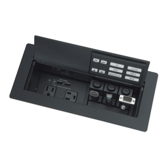
LAPTOP MEDIA VIDEO PLAYER HDMI 1 HDMI 2 MUTE WIRELESS Extron Extro Figure 3. NBP 200 Front (Left) and Rear (Right) Views Cable Cubby Model The NBP 1200C features soft backlit buttons. It is mounted in a Cable Cubby enclosure so it can be integrated into a table, desk, or lectern. -
Page 12: Application Diagrams
Network and configuration features • Global compatibility — The NBPs use industry standard Ethernet communication protocols, including DHCP, DNS, HTTP, HTTPS, ICMP, NTP, SFTP, SMTP, SNMP, SSH, TCP/IP, and UDP/IP. • Network connection — The NBPs support 10Base-T up to 100Base-T Ethernet communication. - Page 13 LAPTOP VIDEO LAPTOP MEDIA PLAYER HDMI 1 HDMI 2 Room MEDIA HDMI Wireless Access MUTE PLAYER Point Ethernet TCP/IP MODEL 80 Network NBP 105 D NBP 110 D Tablet Ethernet Network Network Button Button Panel Panel ShareLink 200 N AUDIO VGA OUT HDMI OUT POWER...
-
Page 14: Pc System Requirements
Computer Display with Speakers Display with Speakers Laptop Laptop HDMI HDMI Extron NBP 1200C Cable Cubby Enclosure with Network Button Panel LAPTOP HDMI 1 HDMI 2 MEDIA PLAYER MUTE Table Ethernet HDMI RS-232 100-240V ~ --A MAX COM 1 COM 2 DIGITAL I/O 4 +V IPCP PRO 250... -
Page 15: Hardware Features And Installation - Wall-Mountable Models
Hardware Features and Installation — Wall-mountable Models This section covers the following material for the decorator-style and US gang models: Overall Configuration Procedure • • Step 1: Get Ready Step 2: Prepare the Installation Site • • Step 3: Change Buttons, Button Labels, a Bezel, or Wallplate (optional) •... -
Page 16: Overall Configuration Procedure
Overall Configuration Procedure Step 1: Get ready. Step 2: Prepare the installation site. Step 3: Change buttons or faceplates, if desired. Step 4: Cable the NBPs and the control processor or HCR receiver, then apply power. Within Global Configurator (GC Professional or See the network network communication... -
Page 17: Step 1: Get Ready
Step 1: Get Ready Preparation Checklist Use the following checklist to prepare for the installation. Familiarize yourself with the features of the button panel (see Front Panel Features (All Models) and NBP 1200C Bottom Panel Features on page 36, Rear and Side Panel Features and Cabling (Decorator-style and US Gang Models) page 16, and Bottom Panel Features and Cabling (NBP 1200C) on page 33) -
Page 18: Step 2: Prepare The Installation Site
Step 2: Prepare the Installation Site Steps and hardware required depend on the model being installed (see Site Preparation on page 11 for details). ATTENTION: Installation and service must be performed by authorized personnel only. • L’installation et l’entretien doivent être effectués uniquement par un technicien •... -
Page 19: Site Preparation
Site Preparation The NBP button panels fit standard US junction boxes or mud rings. Model Gang Size NBP 105 D, NBP 106 D, NBP 108 D, NBP 110 D NBP 50, NBP 100 NBP 200 Optional mud rings, UL Listed junction boxes, external junction boxes, and surface mounting boxes are available for use with the button panels. Read any installation instructions and UL guidelines that come with the mounting devices, then install the box or mud ring in the opening at the installation site. -
Page 20: Step 3: Change Buttons, Button Labels, A Bezel, Or Wallplate (Optional)
Step 3: Change Buttons, Button Labels, a Bezel, or Wallplate (optional) Instructions for Decorator-style Models If desired, replace one or more buttons or button pairs using available additional buttons. Optional button kits are available in various languages. Wallplates and bezels are available in black, as well. - Page 21 Insert a new button or button pair from the back into the appropriate opening in the original or the replacement bezel. Pegs (2) Align the two pegs in the upper left and lower right corners of the button or button pair (see figure 11) with the corresponding holes in the bezel.
-
Page 22: Instructions For Us Gang Models
Instructions for US Gang Models The faceplate, button labels, and knob can easily be changed at any time. Some button labels ship with the unit. You can create and print your own customized labels using Extron Button Label Generator software, which is available in the software Download Center page on the Extron website. -
Page 23: Step 4: Cable All Devices
Step 4: Cable All Devices For the US gang models, if the button panel is not mounted to a grounded metal junction box or a grounded metal equipment rack, Extron recommends connecting the unit to an earth ground to protect the unit from electrostatic discharge. To ground the unit: Securely terminate a grounding cable with a... -
Page 24: Rear And Side Panel Features And Cabling (Decorator-Style And Us Gang Models)
Rear and Side Panel Features and Cabling (Decorator-style and US Gang Models) LAN (Ethernet) and PoE connector and LEDs — Connect the unit to a network via this connector for control and Power over Ethernet. Use the following diagrams as a guide. Network connection lets you configure the control system and the NBP. - Page 25 Code canadien de l’électricité, partie 1, section 16. La source d’alimentation ne devra pas être fixée de façon permanente à une structure de bâtiment ou à une structure similaire. The Network Button Panels are intended to be used with Extron Electronics • UL Listed products only.
-
Page 26: Step 5: Set Up The Nbp For Network Communication
Step 5: Set up the NBP for Network Communication Connect the NBP button panel and Network Communication Setup the PC to be used for setup to the same Ethernet subnetwork. Connect the NBP and PC to the same Start Toolbelt and use it to set DHCP network. -
Page 27: Step 8: Complete The Physical Installation
Step 8: Complete the Physical Installation Mount the unit to a wall or furniture (see “Mounting”, below). Before mounting the NBP, make sure that the Ethernet cable has been fed through the wall or furniture and is connected to the NBP rear panel. NOTES: Extron recommends taking safety precautions to avoid electrostatic discharge •... - Page 28 For US gang models: Insert the included screws through the mounting holes at the top and bottom of the unit, through the plastic spacer (if not using a mud ring), and into the corresponding threaded holes in the box or mud ring (see figure 21 and figure 22).
- Page 29 Attach the wallplate to the NBP For decorator-style models: Insert the included screws through the circular • figure 19 figure 20 holes in the wallplate and the tabs on the NBP (see page 19). Hand tighten the screws using a flat bladed screwdriver until snug. For US gang models: Align the faceplate openings with the buttons, knob, and •...
-
Page 30: Hardware Features And Installation - Nbp 1200C
Hardware Features and Installation — NBP 1200C This section covers the following material for the NBP 1200C: Overall Configuration Procedure, NBP 1200C • • Step 1: Get Ready (NBP 1200C) Step 2: Prepare the Installation Site, Cut the Table or Furniture • • Step 3: Assemble AAP, Pass-through, and Power Modules •... -
Page 31: Overall Configuration Procedure, Nbp 1200C
Overall Configuration Procedure, NBP 1200C Step 1: Get ready. Step 2: Prepare the installation site, cut the table or funiture. Step 3: Assemble AAP, pass-through, and power modules. Step 4: Install modules and a Retractor bracket. Step 5: Change buttons or faceplates, if desired. Step 6: Mount the NBP 1200C to the table. -
Page 32: Step 1: Get Ready (Nbp 1200C)
Step 1: Get Ready (NBP 1200C) Preparation Checklist Use the following checklist to prepare for the installation. Familiarize yourself with the features of the button panel (see Front Panel Features (All Models) and NBP 1200C Bottom Panel Features on page 36 and Bottom Panel Features and Cabling (NBP 1200C) on page 33) Download and install the latest version of the software, firmware, and device drivers... -
Page 33: Included Parts
Included Parts 3 3 3 4 4 4 6 6 6 7 7 7 8 8 8 9 9 9 Figure 24. NBP 1200C Included Parts Item Qty Item Qty Item 6 (3/8") NBP 1200C Retractor pin and clip Grommet hole plugs 2 (1/4") Connectivity bracket #6-32 pan-head... -
Page 34: Prepare The Site
Prepare the Site To prepare the site: Decide on the method for cutting a hole in the table (see “Cut the Table” below). If necessary, obtain the correct cut-out template and verify the dimensions (see the template information below). Protect the surface prior to and during cutting so the surface is not damaged. Cut the Table CAUTION: Wear safety glasses when operating power equipment. -
Page 35: Step 3: Assemble Aap, Pass-Through, And Power Modules
Step 3: Assemble AAP, Pass-through, and Power Modules A variety of modules allow you to populate the Cable Cubby enclosure with a combination of AAPs, cable pass-through plates, retractors, or power modules. The NBP 1200C accommodates your choice of any two modules, allowing you to customize the device to meet your needs. -
Page 36: Step 4: Change Buttons (Optional)
Step 4: Change Buttons (optional) If desired, replace one or more buttons using available additional buttons. Optional button kits are available in various languages. NOTE: A custom button builder tool is available at https://www.extron.com/article/custombuttonbuilder where you can order custom-labeled buttons for the NBP. 2 2 3 3 Insert the Extron removal tool into one of the removal slots in the top edge of the button... -
Page 37: Step 5: Install Modules And A Retractor Bracket
Step 5: Install Modules and a Retractor Bracket Determine where the modules are to be installed in the Cable Cubby enclosure. Any combination of two modules can be installed. The modules can be installed on either side of the enclosure and at various heights. NOTES: Ensure that there is enough room above the modules for the Cable Cubby lid to •... -
Page 38: Aap Module, Cable Pass-Through Module, And Power Module
AAP Module, Cable Pass-through Module, and Power Module Insert the modules into the Cable Cubby as shown in figure 28. Insert the modules into the Cable Cubby. Secure the modules using four of the provided #6-32 pan-head mounting screws and star washers. Figure 28. -
Page 39: Step 6: Mount The Nbp 1200C To The Table
Step 6: Mount the NBP 1200C to the Table Insert the NBP 1200C Enclosure Into the Table CAUTION: The flanged edges of the top of the surface Remove the plastic plastic enclosure are sharp. These strips and lm on m on edges are also soft and the surface of the f the... -
Page 40: Step 7: Install Retractors
Step 7: Install Retractors Retractors can be installed in a vertical, angular, or horizontal orientation. No adjustment of the enclosure screws is needed if the retractors are mounted vertically. To mount at an angle or horizontally, adjust the enclosure screws as shown below. When the retractors are mounted horizontally, the retractor mechanism must be secured to the underside of the table (see the Cable Retractor Setup Guide, available at www.extron.com). -
Page 41: Step 9: Cable The Nbp 1200C And Other Devices In The System
Step 9: Cable the NBP 1200C and Other Devices in the System Bottom Panel Features and Cabling (NBP 1200C) Run a network cable to the NBP 1200C. Connect the NBP to the network via the LAN/PoE port on the bottom panel of the NBP 1200C (as shown in figure 33). - Page 42 725, et du Code canadien de l’électricité, partie 1, section 16. La source d’alimentation ne devra pas être fixée de façon permanente à une structure de bâtiment ou à une structure similaire. The Network Button Panels are intended to be used with Extron Electronics • UL Listed products only.
-
Page 43: Step 10: Set Up The Nbp 1200C For Network Communication
Step 10: Set up the NBP 1200C for Network Communication Connect the NBP button panel and Network Communication Setup the PC to be used for setup to the same Ethernet subnetwork. Connect the NBP and PC to the same Start Toolbelt and use it to set DHCP network. -
Page 44: Operation
Operation This section of the guide covers the following topics: Front Panel Features (All Models) and NBP 1200C Bottom Panel Features • — Locations and descriptions of items on the front panel and the bottom panel features of the NBP 1200C Reset Features and Resetting the Unit —... - Page 45 DISPLAY DISPLAY VOLUME VOLUME LAPTOP VIDEO LAPTOP VIDEO MEDIA PLAYER HDMI 1 HDMI 2 VIDEO MEDIA HDMI LAPTOP MUTE MUTE PLAYER NBP 105 D NBP 106 D NBP 108 D NBP 110 D Figure 36. Decorator-style NBP Front Panels With Wallplates B B B B B B B B B...
- Page 46 Volume LEDs (see figure 36, figure 37, and figure 38 on page 37— Volume LEDs (present only on models with Volume buttons or a volume knob) light to act as a meter to indicate the volume level. Cable Cubby lid (NBP 1200C, see figure 38 on the previous page) —...
-
Page 47: Wallplates And Bezels
Wallplates and Bezels Each decorator-style NBP is shipped with a white bezel and white wallplate and also a black bezel and black wallplate. Each US gang model is shipped with a white faceplate and a black faceplate. Each NBP 100 or NBP 200 is also shipped with a white knob and a black knob. Step 3: Change Buttons, Button Labels, a Bezel, or Wallplate (optional) page 12 for instructions on how to change the bezel, wallplate, faceplate, buttons, or Step 4: Change Buttons (optional) -
Page 48: Volume Controls And Leds
Volume Controls and LEDs You must configure these buttons (NBP decorator-style models, NBP 1200C) or knob (NBP 100 or NBP 200). They can be used for any function and behavior and to control any device. However, the most common configuration is as follows: On the decorator-style models and NBP 1200C: •... - Page 49 Range-based volume adjustment If the system is configured for use with some projectors, the most common way to configure the LEDs on the NBPs is to indicate volume ranges (with steadily lit LEDs), as shown in the following diagrams. Range-based Volume Adjustment — NBP 105 D, NBP 106 D VOLUME VOLUME VOLUME...
-
Page 50: Reset Features And Resetting The Unit
Reset Features and Resetting the Unit Locating the Reset Button and LED The Reset button and LED (shown at right) are RESET located on the front panel of each decorator-style or US gang series unit, behind the wallplate RESET RESET or faceplate (see figure , on page 38) - Page 51 NBP Series Reset Mode Summary Use This Activation Result Mode to... The button panel reverts to the factory Temporarily To start the Use Factory Firmware reset mode and replace boot up the firmware: default firmware. Event scripting does not unit with start if the unit is powered on in this mode.
-
Page 52: Software-Based Configuration And Control
Software-Based Configuration and Control This section of the guide is divided into the following topics: Configuration and Control: an Overview • • Basic Setup Steps: a Guide to this Section and Other Resources Downloading the Software and Getting Started • •... -
Page 53: Basic Setup Steps: A Guide To This Section And Other Resources
Step 1: Get ready. Basic Setup Steps: a Guide to this Section and Other Resources Step 2: Prepare the installation site. NOTE: GC projects can be created offline and uploaded to the hardware at a later date. Step 3: Change buttons or faceplates, if desired. Follow the steps in Hardware Features and Installation —... - Page 54 Via links from the web page for the specific product Navigate to the web page for the specific product model by performing one of the following: Typing the model name into the search field in the upper right of any Extron web •...
-
Page 55: Things To Do After Installing Gc And Before Starting A Project
Things to Do After Installing GC and Before Starting a Project • Read the Global Configurator Help File, included with the software, for details and step- by-step procedures on how to start a GC Professional or GC Plus project and perform basic setup tasks for a control processor or collaboration system receiver. The help file provides a wealth of information on settings and how to use the software. -
Page 56: Troubleshooting
Troubleshooting Turn on the input devices (DVD players, Blu-ray players, PCs, and other sources), output devices (display screens, projectors), the controller, and the PC. Push a front panel button or (for US gang models) rotate the Volume knob. If an input or output AV device cannot be remotely controlled (does not respond as expected), check the following: Power Connections Ensure that all devices are plugged in. -
Page 57: Device Control Connections And Configuration
Device Control Connections and Configuration Verify that ports are wired correctly and that ground (earthing) wires are connected • to the proper pins on the control processor or collaboration system receiver, and, if applicable, on controlled devices. Verify that the NBP is grounded (see grounding instructions on page 15). -
Page 58: Reference Information
Reference Information This section of the guide includes the following reference items: Network Requirements • • Secure Sockets Layer (SSL) Certificates • IEEE 802.1X Certificates To read product specifications, visit the product page for the NBP model at www.extron.com. Network Port Requirements Network administrators may find it useful to know which ports, protocols, and services are used by the button panels, control processors, collaboration receivers, touchpanels, Global Configurator Plus and Professional software, Toolbelt, and Extron Control software. -
Page 59: Ieee 802.1X Certificates
To properly create the certificate for uploading to Extron control devices, ensure that the certificate file meets the following requirements: • contains X.509 certificate information • contains public and private keys • uses PEM encoding NOTE: ITU-T standard X.509 covers aspects of public key encryption, digital cryptography, certificates, and validation. -
Page 60: Private Key File Requirements
To create the 802.1X security certificate for uploading to Extron control processors, ensure that the certificate file meets the following requirements: • It contains X.509 certificate information. • It contains a private key (for machine certificates only). • It is PEM encoded. It has a file extension that is .crt or .pem •... -
Page 61: Firmware Updates
Firmware Updates If the need arises, you can replace the NBP firmware. This section covers the following firmware-related topics: • Determining the Firmware Version Updating the Firmware • Determining the Firmware Version To check which firmware version the button panel is using, do one of the following: •... -
Page 62: Updating The Firmware
Updating the Firmware Firmware upgrade tools require the PC and the NBP to both be connected to an Ethernet network. The instructions for updating the firmware assume you have installed the appropriate software on your PC first. NOTES: You should save the existing configuration to a file (see the Global Configurator •... - Page 63 Extron Electronics makes no further warranties either expressed or implied with respect to the product and its quality, performance, merchantability, or fitness for any particular use. In no event will Extron Electronics be liable for direct, indirect, or consequential damages resulting from any defect in this product even if Extron Electronics has been advised of such damage.
Need help?
Do you have a question about the IP Link Pro NBP 50 and is the answer not in the manual?
Questions and answers