Advertisement
Quick Links
ACP 100 • Setup Guide
The Extron ACP 100 Audio Control Panel is a fully configurable control interface for use with any Extron ACP-enabled device.
Each ACP 100 includes two ACP ports, which support both power and communication between the host device and the
ACP 100. Up to eight ACP panels can be used per host device for more demanding control needs.
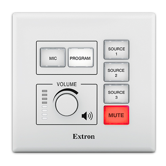
Front Panel Features
A A A
A
B B B
B
MIC
PROGRAM
VOLUME
D D D
D
Extron
ACP 100 Front Panel with Plastic
Faceplate
ACP 100 Front Panel
Figure 1.
Rear Panel Features
ACP 100 Rear Panel
ACP 100 Rear Panel
Figure 2.
Planning the System and Installation
When planning to install an ACP system, consider how many ACP panels to use, maximum cable distance, and mounting (see
the ACP 100 product page at
SOURCE
1
SOURCE
2
C
C C C
SOURCE
3
F
F F F
MUTE
A
A A A
B
B B B
C
C C C
www.extron.com
for more information about the ACP 100).
E
E E E
E
SOURCE
1
MIC
PROGRAM
SOURCE
2
SOURCE
3
RESET
MUTE
ACP 100 Front Panel without
Plastic Faceplate
Plastic Faceplate
A
Function Buttons 1 and 2
B
Function Buttons 3-6
C
Volume LEDs and Knob
D
Mounting Holes (4)
E
Reset Button
F
Bus ID DIP Switches
A
ACP Ports (2)
B
ACP Status LEDs
C
1
Advertisement

Related Manuals for Extron electronics ACP 100


Summary of Contents for Extron electronics ACP 100
- Page 1 ACP 100 • Setup Guide The Extron ACP 100 Audio Control Panel is a fully configurable control interface for use with any Extron ACP-enabled device. Each ACP 100 includes two ACP ports, which support both power and communication between the host device and the ACP 100.
-
Page 2: Step 2: Prepare The Installation Site
Extron recommande d’installer le ACP 100 dans un boîtier d’encastrement électrique mis à la terre, listé UL. • If the ACP 100 will be installed into fine furniture, it is best to hire a licensed, bonded craftsperson to cut the access hole •... - Page 3 Align the button lens cap with the white diffuser and the panel opening, then press the button lens cap into place on the button. Attach the plastic faceplate to the ACP 100. Align the openings of the faceplate with the buttons and knob and place the plastic faceplate against the unit. The four magnetic catches fasten the faceplate onto the unit.
- Page 4 ACP devices that are relatively far from the host device can be connected to an optional Extron PS 1220EB eBUS power inserter or an Extron 12 VDC desktop power supply as shown in the diagrams below and on the next page (see the ACP 100 Specifications at www.extron.com...
- Page 5 +12 VDC on an ACP + Signal 100 or other - Signal G Ground ACP device Ground all Ridged ACP 100 Devices Rear Panel – Return +12 VDC input External Power Supply (12 VDC, 1.5 A max.) Smooth NOTE: Check the polarity of the power NOTE: Check the polarity of the power supply before connecting it to the ACP.
-
Page 6: Device Status
Verify the ACP bus ID DIP switches are set to the desired address on each unit and that there are no bus ID address conflicts in the system. The ACP 100 may have a single monochrome LED (green) or three separate LEDs (green, amber, or red). The LED (or LEDs) are a diagnostic tool showing the device status:... - Page 7 Ensure the cables are connected to the ACP 100 rear panel. Mount the ACP 100 as follows: Insert the cabled ACP 100 into the mud ring or junction box within the wall or furniture, aligning the mounting holes in the ACP 100 with those in the box or mud ring.
- Page 8 For information on safety guidelines, regulatory compliances, EMI/EMF compatibility, accessibility, and related topics, see the Extron Safety and Regulatory Compliance Guide on the Extron website. www.extron.com © 2017-2019 Extron Electronics — All rights reserved. 68-3065-50 Rev. B All trademarks mentioned are the property of their respective owners. 07 19...
Need help?
Do you have a question about the ACP 100 and is the answer not in the manual?
Questions and answers