Table of Contents
Advertisement
Quick Links
eBUS
Button Panel Decorator-Style Series • Setup Guide
®
Overview
Extron offers a range of eBUS Button Panels (EBPs) in the decorator-style form factor that can be mounted in walls or furniture
in any standard US 1-gang opening. Each panel is a fully customizable AV system control interface for use with Extron IPCP Pro
Series control processors. Individual EBPs are easily configured and can be connected with other panels to provide control for
large and complex AV systems.
NOTE: These products are only for use with Extron UL Listed IPCP Pro control processors.
Each EBP button panel has two eBUS ports that support power and communications between the IPCP Pro control processor
and eBUS devices. Up to eight eBUS devices such as EBP button panels can be connected to the control processor and to each
other in various cabling topologies. Cabling topology refers to the physical layout of cabling interconnections between devices
in a network such as an eBUS system. eBUS systems can include daisy chain, star, or hybrid (a combination of both) system
topologies (see the eBUS Technology Reference Guide, available on
have a unique identification address (eBUS ID) within the system.
Setup involves setting eBUS ID DIP switches on the EBPs, then using Extron Global Configurator
software, the Toolbelt utility, or Global Scripter
AV system can be controlled from any of its EBPs.
This guide provides basic instructions for an experienced installer to install the EBP decorator-style series button panels.
For more details on the EBPs, see the eBUS Technology Reference Guide, available on www.extron.com. For details on
configuration or programming, see the software help files.
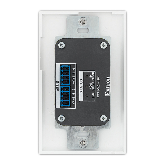
EBP Rear and Side Panel Features
Figure 1 shows the side and rear views of the EBP 105 D and the rear view of the EBP 103 D. The EBP 105 D side features are
very similar for all EBP decorator-style models except the EBP 103 D. The EBP 105 D rear features are the same for all EBP
decorator-style models except the EBP 103 D.
A A
B B
EBP 103 D Rear View
EBP 105 D and EBP 103 D Rear and Side Views.
Figure 1.
A
eBUS connectors (2 ports) — The four-pole captive screw connectors use the Extron eBUS protocol to connect the panel to
a controller and to other panels (see
B
Status LEDs — Provide diagnostic information about the connection, communication, and power status of the panels.
The EBP 103 D has amber, red, and green LEDs.
z
All other EBP decorator-style models have a single green LED.
z
For more information about how the LEDs are used for troubleshooting, see
C
DIP switches — Up to eight devices can be connected to one control processor. Each device connected to the same control
processor must have a unique eBUS ID, which is set using DIP switches (see
D
Reset button — Resets the firmware to the factory installed version (see
programming software, to configure the control processor. Once configured, the
®
D D
C C
EBP 103 D Side View
EBP 105 D Rear View
Step 5: Cable All Devices
www.extron.com,
for basic diagrams). Every device must
D D
A A
B B
C C
EBP 105 D Side View
on page 9).
Step 7: Test and Troubleshoot
Step 4: Set the eBUS ID
To reset the firmware
Product Category
Plus and Professional
®
on page 11.
on page 6).
on the next page).
1
Advertisement
Table of Contents

Subscribe to Our Youtube Channel
Related Manuals for Extron electronics eBUS Button Panel Decorator-Style Series


Summary of Contents for Extron electronics eBUS Button Panel Decorator-Style Series
- Page 1 Product Category eBUS Button Panel Decorator-Style Series • Setup Guide ® Overview Extron offers a range of eBUS Button Panels (EBPs) in the decorator-style form factor that can be mounted in walls or furniture in any standard US 1-gang opening. Each panel is a fully customizable AV system control interface for use with Extron IPCP Pro Series control processors.
-
Page 2: Ebp Front Panel Features
Button Panel Decorator-Style Series • Setup Guide (Continued) To reset the firmware button (see figure 2, ) for the EBP 103 D can only be accessed from the front of Reset the unit, after removing the frame (see Remove the frame and bezel on page 4). -
Page 3: Planning The System And Installation
Product Category Planning the System and Installation When planning to install an eBUS system, consider how many EBP button panels to use, maximum cable distance, cabling topology, and mounting. See the eBUS Technology Reference Guide for more information about eBUS topologies. Installation Step 1: Get Ready Use the following check list to prepare for the installation. - Page 4 Button Panel Decorator-Style Series • Setup Guide (Continued) Remove the rotary encoder knob (EBP VC1 only) The EBP VC1 D has a rotary encoder knob. Before replacing buttons, remove the encoder, as shown here. Use an Allen wrench Turn the rotary encoder knob (figure 4, ) to expose the to loosen the screw.
- Page 5 Product Category Replace button labels for the EBP 103 D You can replace one or more of the labels within the buttons. Some button labels ship with the unit. You can create and print your own customized labels using Extron Button Label Generator software.
- Page 6 Button Panel Decorator-Style Series • Setup Guide (Continued) Step 4: Set the eBUS ID Up to eight devices can be connected to one control processor. In order for the control processor to be successfully configured, each device connected to...
- Page 7 Product Category Setting eBUS ID Numbers In the table below, a DIP switch setting shown as 0 is equivalent to Off. A DIP switch setting shown as 1 is equivalent to On. NOTE: The ID number 0 (switch setting 000000) is reserved for the control processor and cannot be used by an eBUS device. DIP Switch Setting Decimal DIP Switch Setting...
- Page 8 Button Panel Decorator-Style Series • Setup Guide (Continued) DIP Switch Setting Decimal DIP Switch Setting Decimal Value Value 1 2 3 4 5 6 1 2 3 4 5 6 1 2 3 4 5 6 1 2 3 4 5 6...
- Page 9 Product Category Step 5: Cable All Devices Attach cables using the diagrams in this section as a guide. Connect a 4-pole captive screw connector to each end of the cable, wiring both ends as shown in figure 7. In most cases the EBPs are powered by the IPCP Pro control processor that provides the eBUS signal.
- Page 10 Button Panel Decorator-Style Series • Setup Guide (Continued) EBPs that are relatively far from the control processor (see the eBUS Technology Reference Guide on www.extron.com details) can be connected to an optional Extron PS 1220EB eBUS power supply and distribution hub, or an Extron PS series desktop power supply as shown in the following diagrams.
-
Page 11: Step 6: Configure The System
Product Category Step 6: Configure the System EBPs are shipped with pre-labelled buttons in place but these buttons do not have any functions associated with them until they are configured with Global Configurator or programmed with Global Scripter. See the Global Configurator Help File or the Global Scripter Help File for step-by-step instructions and detailed information. -
Page 12: Before Mounting
Button Panel Decorator-Style Series • Setup Guide (Continued) Step 8: Mount the EBPs EBP panels can be installed directly into the wall using a 1-gang or 2-gang (EBP 111D) wall mounting bracket (mud ring) or a UL Listed junction box. Figures 13 (below) and 14 (on the next page) show how to mount a 1-gang EBP. Use the same procedure to mount the two-gang EBP 111 D. - Page 13 Product Category Mounting with a UL Listed Electrical Junction Box Install the junction box by following the instructions provided by the manufacturer. Use the two provided Phillips head screws to secure the module to the junction box ( Use the two screws provided to secure the frame to the module ( Electrical Junction Frame...
- Page 14 Button Panel Decorator-Style Series • Setup Guide (Continued) © 2016 - 2018 Extron Electronics All rights reserved. All trademarks mentioned are the property of their respective owners. www.extron.com 68-1449-50 Rev. D 03 18...
Need help?
Do you have a question about the eBUS Button Panel Decorator-Style Series and is the answer not in the manual?
Questions and answers