Extron electronics MKP 2000 User Manual
Remote control panel
Hide thumbs
Also See for MKP 2000:
- Specifications (2 pages) ,
- User manual (43 pages) ,
- User manual (56 pages)
Table of Contents
Advertisement
Quick Links
Download this manual
See also:
User Manual
Extron Electronics, USA
Extron Electronics, Europe
1230 South Lewis Street
Beeldschermweg 6C
Anaheim, CA 92805
3821 AH Amersfoort
USA
The Netherlands
714.491.1500
+31.33.453.4040
www.extron.com
Fax 714.491.1517
Fax +31.33.453.4050
© 2005 Extron Electronics. All rights reserved.
Extron Electronics, Asia
Extron Electronics, Japan
135 Joo Seng Road, #04-01
Kyodo Building
PM Industrial Building
16 Ichibancho
Singapore 368363
Chiyoda-ku, Tokyo 102-0082 Japan
+65.6383.4400
+81.3.3511.7655
Fax +65.6383.4664
Fax +81.3.3511.7656
User's Manual
MKP 2000
Remote Control Panel
68-971-01 Rev. A
01 05
Advertisement
Table of Contents

Subscribe to Our Youtube Channel
Related Manuals for Extron electronics MKP 2000


Summary of Contents for Extron electronics MKP 2000
- Page 1 Fax 714.491.1517 Fax +31.33.453.4050 Fax +65.6383.4664 © 2005 Extron Electronics. All rights reserved. User’s Manual Extron Electronics, Japan Kyodo Building 16 Ichibancho Chiyoda-ku, Tokyo 102-0082 Japan +81.3.3511.7655 Fax +81.3.3511.7656 MKP 2000 Remote Control Panel 68-971-01 Rev. A 01 05...
- Page 2 Precautions Safety Instructions • English Warning This symbol is intended to alert the user of important Power sources • This equipment should be operated only from the power source indicated on the product. This equipment is intended to be used with a main operating and maintenance (servicing) instructions power system with a grounded (neutral) conductor.
- Page 3 Quick Start Guide — MKP 2000 Install and set up the MKP 2000 as follows: Step 1 Turn all of the equipment off and disconnect it from the power source. Step 2 Install the cables to and from the control panel in a wall, podium, or desk.
-
Page 4: Table Of Contents
See System Settings Page in chapter 5, HTML Operation. Step 11 Use the control panel to select inputs and outputs. See Front Panel Operations in chapter 3, Local Operation. MKP 2000 Remote Control Panel • Quick Start Guide QS-2 Table of Contents Chapter 1 • Introduction ... -
Page 5: Chapter 1 • Introduction
Electrical box cutout ... A-4 Panel mount cutout template ... A-4 Extron Comm-Link cable ... A-6 All trademarks mentioned in this manual are the properties of their respective owners. MKP 2000 Remote Control Panel • Table of Contents ... 5-7 ... 5-8 ... A-4... -
Page 6: Chapter 2 • Installation
Web pages. The MKP 2000 is mounted in a two-gang wall plate that can be installed in a wall, conference table, podium, or other convenient location. -
Page 7: Chapter 2 • Installation
Introduction Chapter Two Installation MKP Installation Overview UL Requirements for Wall Box Installation Installation Procedures Rear Panel and Side Panel Connections MKP 2000 Remote Control Panel • Introduction MKP 2000 Remote Control Panel • Introduction... -
Page 8: Mkp Installation Overview
MKP 2000 Remote Control Panel • Installation UL Requirements for Wall Box Installation The following Underwriters Laboratories (UL) requirements pertain to the installation of the MKP 2000 into a wall or furniture (figure 2-1). IN PU Figure 2-1 — MKP mounted in a wall box These units are not to be connected to a centralized DC power source or used beyond their rated voltage range. -
Page 9: Preparing The Site, Installing The Mud Ring Or Wall Box
Enlarge or smooth the edges of the opening if needed. MKP 2000 Remote Control Panel • Installation If you are using a wall box, feed cables through the wall box punch-out holes, and secure them with cable clamps to provide strain relief. -
Page 10: Mounting The Mkp To The Mud Ring Or Wall Box
If attaching the wall box to metal studs or furniture, use four #8 or #10 self-tapping sheet metal screws or machine bolts with matching nuts. MKP 2000 Remote Control Panel • Installation IN P Wall Stud Wall Box... -
Page 11: Rear Panel And Side Panel Connections
RS-232 12 VDC Figure 2-6 — MKP rear and side panels MKP 2000 Remote Control Panel • Installation LAN (Ethernet) port — If desired, connect a Category (CAT) 5e or higher (network) cable between this connector and either the matrix switcher to be controlled or to an Ethernet local area network (LAN). -
Page 12: Control Connections
MKP 2000 Figure 2-9 — Direct MKP connection using the LAN port 2-10 MKP 2000 Remote Control Panel • Installation ) and a Switcher Matrix Switcher 9 10 11 12 13 14 15 16 17 18 19 20 21 22 23 24... -
Page 13: Tp Cable Termination
(figure 2-9). • Patch (straight) cable — Network connection between the MKP and an Ethernet LAN (figure 2-10). 2-12 MKP 2000 Remote Control Panel • Installation Patch (straight) cable Side 1 Pin Wire color Pin Wire color 1 White-orange... -
Page 14: Front Panel Operations
Alternatively, an Extron P/S 100 Universal 12 VDC Power Supply, part #60-357-01, can power up to ten Extron 12 VDC devices using only one AC power connector. MKP 2000 Remote Control Panel • Installation 2-14 0.2” (5 mm) Direct Insertion... -
Page 15: Front Panel Controls And Indications
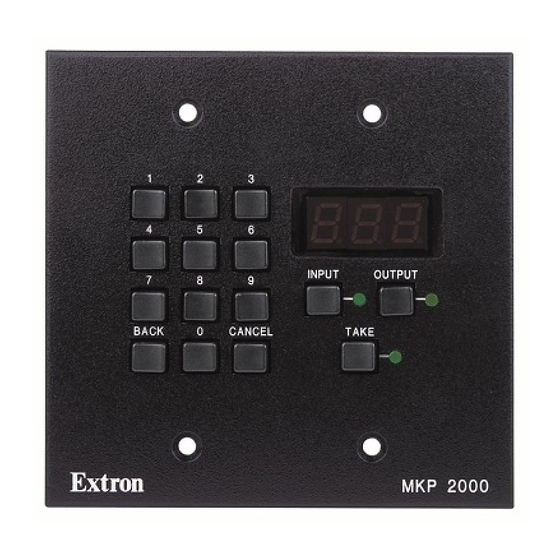
CANCEL CANCEL TAKE Figure 3-1 — MKP 2000 controls and indicators 0, 1 through 9 buttons — These buttons allow you to enter an input or output when you create a tie. Back button — This button allows you to delete the least- significant (rightmost) digit of an entered input or output number. -
Page 16: Viewing The Last Input Or Output Tied From The Mkp
MKP. Extron recommends editing this field using the front panel or the RS-232 link MKP 2000 Remote Control Panel • Local Operation and protecting the Ethernet access to these parameters by assigning an administrator’s password to qualified and knowledgeable personnel only. -
Page 17: Host Control Port Setting And Pass-Through Communications
Connected to Control Though Switcher Primary (RS-232) OUTPUT OUTPUT Figure 3-2 — Selecting octet fields and host control MKP 2000 Remote Control Panel • Local Operation OUTPUT OUTPUT 2 5 4 2 5 3 0 0 0 0 0 0... -
Page 18: Control Panel Security Lockout (Executive Mode)
255.255.0.0. This function is identical to the ZQQQ SIS command, see chapter 4, SIS Operation). MKP 2000 Remote Control Panel • Local Operation seconds Perform a soft reset of the MKP as follows: Press and hold the Reset (R) button until the Reset LED blinks off once (events reset), twice (IP system reset), or three times (absolute reset) (figure 3-4). -
Page 19: Performing A Hard Reset
Power The LED flashes on and off. Release the Reset button. Figure 3-5 — Hard reset 3-10 MKP 2000 Remote Control Panel • Local Operation MKP 2000 Remote Control Panel Chapter Four SIS Operation Host-to-MKP Instructions MKP-Initiated (Unsolicited) Messages MKP Error Responses... -
Page 20: Rs-232 Links
RS-232 port only if the MKP is set to Pass-through mode. See the pass-through port redirect command set on page 4-8 to set the Pass-through mode. MKP 2000 Remote Control Panel • SIS Operation Ethernet Link The rear panel LAN connector on the MKP can be connected... -
Page 21: Mkp Error Responses
The table below shows the hexadecimal equivalent of each ASCII character used in the command/response tables. MKP 2000 Remote Control Panel • SIS Operation ASCII to HEX Conversion Table Space The MKP always redirects a subset of valid matrix switcher- specific SIS commands on its Ethernet port and, if configured in pass-through mode, on its Switcher RS-232 port. -
Page 22: Symbol Definitions For Mkp Sis Commands
•CN = Security level 0 = clear/none 11 = user password assigned 12 = administrator password assigned MKP 2000 Remote Control Panel • SIS Operation 1 = on/enable 2 = switcher = “3L” command. = Name 12 characters maximum. - Page 23 SIS Operation, cont’d MKP 2000 Remote Control Panel • SIS Operation MKP 2000 Remote Control Panel • SIS Operation...
- Page 24 SIS Operation, cont’d 4-10 MKP 2000 Remote Control Panel • SIS Operation MKP 2000 Remote Control Panel • SIS Operation 4-11...
-
Page 25: System Status Page
MKP 2000 Remote Control Panel Chapter Five HTML Operation Download the Startup Page System Status Page System Settings Page Port (RS-232) Settings Page Passwords Page Firmware Upgrade Page File Management Page Special Characters MKP 2000 Remote Control Panel • SIS Operation 4-14... -
Page 26: Download The Startup Page
{space} + ~ , @ = ‘ [ ] { } < > ’ “ ; : | \ and ?. MKP 2000 Remote Control Panel • HTML Operation Press the keyboard Enter key. The MKP checks to see if it is password protected. -
Page 27: System Status Page
Status page from other MKP HTML web pages by clicking the Status tab. Figure 5-2 — System Status page MKP 2000 Remote Control Panel • HTML Operation System Settings Page You can change most of the IP parameters on the System Settings page (figure 5-3). -
Page 28: Ip Settings Section
MKP) Host Control Port settings If the RS-232 radio button is selected in the Switcher Control Method box, click the MKP 2000 or Control System Pass Through radio button to select that function for the Host RS-232 port. -
Page 29: Authorized Inputs And Authorized Outputs
When Daylight Savings Time is turned off, the switcher does not adjust its time reference. MKP 2000 Remote Control Panel • HTML Operation Port (RS-232) Settings Page The Port Settings page (figure 5-4) allows you to configure the MKP’s two (Host and Switch) RS-232 ports. -
Page 30: Passwords Page
MKP control panel, do not set a user password on the primary MKP. 5-10 MKP 2000 Remote Control Panel • HTML Operation Firmware Upgrade Page The Firmware Upgrade page provides a way to replace the firmware that is coded on the MKP’s control board without taking the MKP out of service, opening the enclosure, and replacing the firmware chip. -
Page 31: File Management Page
When the LED display shows ... , the firmware upload is complete. 5-12 MKP 2000 Remote Control Panel • HTML Operation File Management Page To delete files such as HTML pages from the switcher or to upload your own files to the switcher, click the File Management tab. -
Page 32: Special Characters
Cannot include spaces or underscore characters • Cannot start with a number or a dash • Cannot end with a dash 5-14 MKP 2000 Remote Control Panel • HTML Operation MKP 2000 Remote Control Panel A ppendix A Reference Data Mounting and Cabling Specifications Specifications... -
Page 33: Specifications
MKP 2000 Remote Control Panel MKP 2000, black MKP 2000, white MKP 2000, RAL 9010 (off white) Included parts These items are included in each order for an MKP 2000: Included parts MKP 2000 12 VDC, 1A external power supply MKP 2000 user’s guide... -
Page 34: Mounting And Cabling Specifications
Drawn to scale; may be used as a template. MKP 2000 Remote Control Panel • Reference Data 3.38” 2.63”... -
Page 35: Extron Comm-Link Cable
B (violet or blue) = 22 AWG (grouped and shielded) C (white) = 22 AWG D (Drain) = 24 AWG E (black) = 18 AWG Comm-Link cable was designed for use with MKP control panels Figure A-2 — Comm-Link cable MKP 2000 Remote Control Panel • Reference Data...
Need help?
Do you have a question about the MKP 2000 and is the answer not in the manual?
Questions and answers