Table of Contents
Advertisement
Quick Links
Network Button Panel — Decorator-Style Series •
Setup Guide
Overview
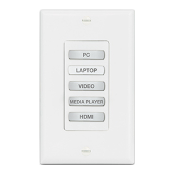
The Extron NBP Network Button Panels are fully customizable AV system control interfaces for use with Extron control processors
(IPCP Pro, IPCP Pro Q xi, IPCP Pro xi,or IPL Pro Series and collaboration system products). The NBPs in this guide fit a standard
US one-gang electrical junction box or mud ring. They have one-gang decorator-style wallplates (one white, one black for each
NBP), front panel bezels (white and black), and a one-gang mud ring. Each NBP button panel has a single LAN port, which
supports both power and communications between the control processor and button panels.
Use Extron Toolbelt software to discover and manage NBP button panels and assign each one a unique IP address. Then
use Extron Global Configurator
Deployment Utility to configure the control system, including the buttons on NBPs. Once configured, the AV system can be
controlled from any of the NBPs.
This guide provides basic instructions for an experienced installer to install an NBP 105 D, NBP 106 D, NBP 108 D, NBP 110 D,
NBP VC1 D, or NBP VC2 D button panel. For more details on the NBPs, see the Network Button Panels User Guide, available on
www.extron.com. For details on configuration, see the software help files.
Conventions Used in This Guide
Throughout this guide a Network Button Panel is also referred to as an "NBP" or "button panel."
•
The NBPs are compatible with the following control devices:
•
IPCP Pro and IPL Pro control processors
•
IPCP Pro Q xi and IPCP Pro xi control processors
•
HCR 102 collaboration system receiver (part of an HC 400 Series system)
•
In this guide, those devices are referred to as "control processors."
For details on those devices, see the IPCP Pro Series User Guide, IPL Pro Series User Guide, IPCP Pro Q xi and xi Series User
Guide, or HC 400 Series User Guide (avail able from www.extron.com).
Global Configurator software is referred to as "GC," which can be run as Global Configurator Professional or Global
•
Configurator Plus.
Global Scripter (GS) and ControlScript Deployment Utility can be used as programming-based alternatives to GC.
•
The GlobalViewer
®
•
(GC) Plus and Professional software, Global Scripter
®
Enterprise application is sometimes referred to as "GVE."
programming, or the ControlScript
®
®
1
Advertisement
Table of Contents

Related Manuals for Extron electronics Decorator-Style Series


Summary of Contents for Extron electronics Decorator-Style Series
- Page 1 Network Button Panel — Decorator-Style Series • Setup Guide Overview The Extron NBP Network Button Panels are fully customizable AV system control interfaces for use with Extron control processors (IPCP Pro, IPCP Pro Q xi, IPCP Pro xi,or IPL Pro Series and collaboration system products). The NBPs in this guide fit a standard US one-gang electrical junction box or mud ring.
-
Page 2: Front Panel Features
Network Button Panel — Decorator-Style Series • Setup Guide (Continued) Front Panel Features DISPLAY DISPLAY VOLUME VOLUME LAPTOP VIDEO LAPTOP VIDEO MEDIA PLAYER HDMI 1 HDMI 2 VIDEO MEDIA HDMI LAPTOP MUTE MUTE PLAYER NBP 105 D NBP 106 D... -
Page 3: Rear Panel Features
Rear Panel Features LAN (Ethernet) and PoE connector and LEDs — Connect the unit to a network via this connector for control and Power over Ethernet. Use the following diagrams as a guide. All NBP one-gang decorator-style models have identical rear panel features. LAN/PoE (Ethernet and NBP Rear Panel Power Over Ethernet) -
Page 4: Step 2: Prepare The Installation Site
Network Button Panel — Decorator-Style Series • Setup Guide (Continued) For systems that will use IEEE 802.1X security, obtain a PEM-encoded security certificate and private key (see “IEEE 802.1X • Certificates” in the NBP Series User Guide) from your IT department. - Page 5 Step 3: Change Buttons, a Bezel, or Wallplate (optional) If desired, replace the wallplate, bezel, and rotary encoder knob (NBP VC1 D); or replace one or more buttons or button pairs using available additional buttons. Optional button kits are available in various languages. Wallplates and bezels are available in black, as well as white.
- Page 6 Network Button Panel — Decorator-Style Series • Setup Guide (Continued) Module Reattach the original bezel or attach the replacement bezel to the unit as follows: Align the tabs (at the top and bottom) and pegs (at the upper left and lower right corners) on the back of the bezel Bezel with the slots and holes on the front of the mounting plate.
-
Page 7: Step 6: Configure The System
Step 5: Set Up the NBP for Network Communication Ensure that the PC you will use for setup and the Network Communication Setup NBP button panel are connected to the same Ethernet subnetwork. Connect the NBP and PC to the same network. Start Toolbelt and use it to set the DHCP status or to set Apply power to all devices. - Page 8 Network Button Panel — Decorator-Style Series • Setup Guide (Continued) Mounting NOTES: • Extron recommends taking safety Wall precautions to avoid electrostatic discharge issues during installation • For best results, Extron recommends grounding the NBP if the junction box or mud rings are not already grounded (see the instructions in the user guide).
-
Page 9: Reset Modes: A Brief Summary
Reset Modes: a Brief Summary The NBP Series button panels offer the following reset modes: Use Factory Firmware: Press and hold the Reset button while applying power to the unit. Keep holding the button • down until the Reset LED blinks twice, or for 6 seconds, then release the button. The unit enters factory firmware mode. -
Page 10: Overall Configuration Procedure
Network Button Panel — Decorator-Style Series • Setup Guide (Continued) Overall Configuration Procedure Step 1: Get ready. Step 2: Prepare the installation site. Step 3: Change buttons or faceplates, if desired. Step 4: Cable the NBPs and the control processor, then apply power.
Need help?
Do you have a question about the Decorator-Style Series and is the answer not in the manual?
Questions and answers