Table of Contents
Advertisement
Quick Links
eBUS
Button Panel EU and MK Series • Setup Guide
®
Overview
Extron offers a range of eBUS Button Panels (EBPs) in one-gang EU and MK form factors. They can be mounted into one-gang
EU or MK enclosures and can also be mounted alongside other EU, MK, or Flex55 products in larger enclosures. Each panel is a
fully customizable AV system control interface for use with Extron IPCP Pro Series control processors. Individual EBPs are easily
configured and can be connected with other panels to provide control for large and complex AV systems.
NOTE: These products are only for use with Extron UL Listed IPCP Pro controller products.
Each EBP button panel has two eBUS ports that support power and communications between the IPCP Pro control processor
and eBUS devices. Up to eight eBUS devices such as EBP button panels can be connected to the control processor and to each
other in various cabling topologies. Cabling topology refers to the physical layout of cabling interconnections between devices
in a network such as an eBUS system. eBUS systems can include daisy chain, star, or hybrid system (a combination of both)
topologies (see the eBUS Technology Reference Guide, available on
have a unique identification address (eBUS ID) within the system.
Setup involves setting eBUS ID DIP switches on the EBPs, then using Extron Global Configurator
software, the Toolbelt utility, or Global Scripter programming software, to configure the control processor. Once configured, the AV
system can be controlled from any of its EBPs.
This guide provides basic instructions for an experienced installer to install the EBP EU or MK series button panels. For more
details on the EBPs, see the eBUS Technology Reference Guide, available on www.extron.com. For details on configuration or
programming, see the software help files.
EBP Rear Panel Features
B B B
A A A
C C C
EBP 104 EU and EBP 104 MK Models
EBP EU Models: Rear View
Figure 1.
The features shown in figure 1 are the same for all EBP EU and MK models, except for the EBP 104 EU and EBP 104 MK.
A
DIP switches — Up to eight devices can be connected to one control processor. Each device connected to the same control
processor must have a unique eBUS ID, which is set using DIP switches (see
B
eBUS connectors (2 ports) — The four-pole captive screw connectors use the Extron eBUS protocol to connect the panel to
a controller and to other panels (see
C
eBUS connection status LEDs — Provide diagnostic information about the connection, communication, and power status
of the panels.
The EBP 104 EU and EBP 104 MK has a single LED that can light yellow, red, or green.
z
All other EBP Decorator-style models have a single green LED.
z
For more information about how the LEDs are used for troubleshooting, see
D
Reset button — Resets the firmware to the factory installed version. To reset the firmware:
Disconnect the eBUS cable that is providing power.
1.
While reconnecting power, press and hold down the Reset button.
2.
Release the Reset button 1 second after reconnecting power.
3.
During the reset process, the front panel buttons are not lit. When the eBUS Status LED lights, the reset process is
complete, and the EBP is functioning normally. For the EBP 104 EU and EBP 104 MK, the green Link LED lights to show
that the EBP is functioning normally.
B B
D D D
A A
Other EBP EU and MK Models
Step 5: Cable All Devices
www.extron.com,
D D
C C
Step 4: Set the eBUS ID on page
on page 9).
Step 7: Test and Troubleshoot
Product Category
for basic diagrams). Every device must
Plus and Professional
®
on page 11.
6).
1
Advertisement
Table of Contents

Related Manuals for Extron electronics eBUS Button Panel EU Series


Summary of Contents for Extron electronics eBUS Button Panel EU Series
- Page 1 Product Category eBUS Button Panel EU and MK Series • Setup Guide ® Overview Extron offers a range of eBUS Button Panels (EBPs) in one-gang EU and MK form factors. They can be mounted into one-gang EU or MK enclosures and can also be mounted alongside other EU, MK, or Flex55 products in larger enclosures. Each panel is a fully customizable AV system control interface for use with Extron IPCP Pro Series control processors.
-
Page 2: Ebp Front Panel Features
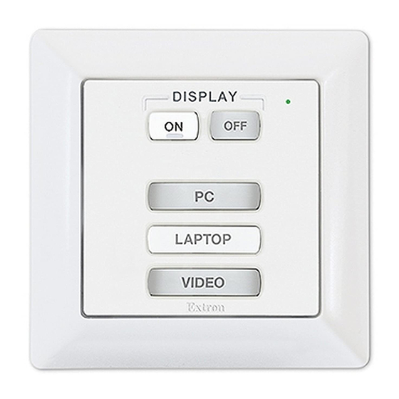
eBUS Button Panel EU and MK Series • Setup Guide (Continued) ® EBP Front Panel Features Figure 2 shows the range of EBP EU front panels. The EBP MK series is the same except for the wall frame surrounding the button plate. -
Page 3: Planning The System And Installation
Product Category Planning the System and Installation When planning to install an eBUS system, consider how many EBP button panels to use, maximum cable distance, cabling topology, and mounting. See the eBUS Technology Reference Guide for more information about eBUS topologies. Installation Step 1: Get Ready Use the following check list to prepare for the installation. -
Page 4: Remove The Bezel
eBUS Button Panel EU and MK Series • Setup Guide (Continued) ® Remove the rotary encoder knob (VC1 models only) The EBP VC1 EU and EBP VC1 MK have a rotary encoder knob. Before replacing the buttons, remove the encoder, as shown here. - Page 5 Product Category Separate the bezel from the button board (all models) Insert a small flat-bladed screw driver into one of the slots (see figure 6, ). There are two slots on each side. Press in the blade of the screw driver until the tab is pushed out of the slot (there is an audible click when this happens).
- Page 6 eBUS Button Panel EU and MK Series • Setup Guide (Continued) ® Step 4: Set the eBUS ID Up to eight devices can be connected to one control processor. In order for the control processor to be successfully configured, each device connected to the same control processor must have a unique six-bit, eBUS ID, which is set with the DIP switch assembly on the rear panel of the EBP (figure 9, ).
- Page 7 Product Category DIP Switch Setting Decimal DIP Switch Setting Decimal Value Value 1 2 3 4 5 6 1 2 3 4 5 6 1 2 3 4 5 6 1 2 3 4 5 6 1 2 3 4 5 6 1 2 3 4 5 6 1 2 3 4 5 6 1 2 3 4 5 6...
- Page 8 eBUS Button Panel EU and MK Series • Setup Guide (Continued) ® DIP Switch Setting Decimal DIP Switch Setting Decimal Value Value 1 2 3 4 5 6 1 2 3 4 5 6 1 2 3 4 5 6 1 2 3 4 5 6 1 2 3 4 5 6 1 2 3 4 5 6...
- Page 9 Product Category Step 5: Cable All Devices Attach cables using the diagrams in this section as a guide. Connect a 4-pole captive screw connector to each end of the cable, wiring both ends as shown in figure 11. In most cases the EBPs are powered by the IPCP Pro control processor that provides the eBUS signal.
- Page 10 eBUS Button Panel EU and MK Series • Setup Guide (Continued) ® EBPs that are relatively far from the control processor (see the eBUS Technology Reference Guide on www.extron.com details) can be connected to an optional Extron PS 1220EB eBUS power supply and distribution hub, or an Extron PS series desktop power supply as shown in the following diagrams.
-
Page 11: Step 6: Configure The System
Product Category Step 6: Configure the System EBPs are shipped with pre-labelled buttons in place but these buttons do not have any functions associated with them until they are configured with Global Configurator or programmed with Global Scripter. See the Global Configurator Help File or the Global Scripter Help File for step-by-step instructions and detailed information. -
Page 12: Prior To Mounting
eBUS Button Panel EU and MK Series • Setup Guide (Continued) ® Prior to mounting: If it has not already been done, feed all device cables through the wall or furniture. Ensure that cables are connected to the EBP rear panel (see EBP Rear Panel Features on page 1). -
Page 13: Mounting Ebp Eu Devices In A Raceway
Product Category Mounting EBP EU Devices in a Raceway NOTES: • If there is a gap between the metal mounting bracket and the wall frame, insert the provided raceway spacer between the mounting bracket and the rim of the junction box (see figure 16). The spacer looks very similar to the metal mounting bracket, but has a slightly larger center opening, has holes instead of slots for the mounting screws, and is engraved with the words “Optional Spacer”... -
Page 14: Removing Ebp Eu Or Mk Wallplates
Remove the screws holding the metal bracket to the wall box EBP 106 EU Removing the EBP 106 EU Figure 17. © 2016 - 2018 Extron Electronics All rights reserved. All trademarks mentioned are the property of their respective owners. www.extron.com 68-1449-50 Rev. C 03 18...
Need help?
Do you have a question about the eBUS Button Panel EU Series and is the answer not in the manual?
Questions and answers