Extron electronics IPCP Pro Series Setup Manual
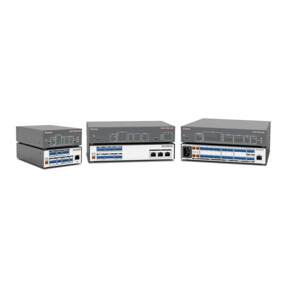
The extron ipcp pro series ip link pro control processors integrate ethernet connection into av systems to allow users to remotely control, monitor, and troubleshoot av equipment, including display devices and switchers
Hide thumbs
Also See for IPCP Pro Series:
- User manual (67 pages) ,
- Setup manual (17 pages) ,
- User manual (72 pages)
Table of Contents
Advertisement
Quick Links
IPCP Pro Series • Setup Guide
The Extron IPCP Pro Series IP Link
remotely control, monitor, and troubleshoot AV equipment, including display devices and switchers. All models include an
embedded web server. Depending on the model, an IPCP Pro control processor can include multiple bidirectional serial ports,
relays, IR/serial ports, digital I/O, flex I/O, switched 12 VDC power output ports, a volume control port, or contact input ports for
use in applications that require control and monitoring of multiple devices within a large-scale AV system.
All models include an Extron eBUS port, which allows a variety of eBUS devices to be connected to a single control processor.
eBUS devices include an array of button panels as well as power and signal hubs. eBUS devices are automatically recognized by
the control processor and can be added or removed at any time.
The dual-NIC (network interface controller) models feature two network interfaces. One (at the LAN port) is for connection to the
corporate or "house" network. The second network interface (at the AV LAN port) is for dedicated control of local AV devices.
This guide provides instructions for an experienced installer to install an IPCP Pro Series control processor and to create a basic
configuration.
Use the Extron Toolbelt software to discover and manage the IPCP Pro control processor and other Extron control products.
Configure the control processor using Extron Global Configurator software running in Global Configurator Professional
(GC Professional) or Global Configurator Plus (GC Plus) mode, or program the control processor using Extron Global Scripter (GS).
The IPCP integrates seamlessly with Extron GlobalViewer
Android for remote control applications. These control processors support multiple TouchLink
standard Ethernet network. Global Configurator and other useful software applications are available at www.extron.com.
Setup Checklist: How to Proceed With Installation
Get Ready
…
Familiarize yourself with the features of the control processor (see
Front Panel Features — Dual-NIC Models
Rear Panel Features — Dual-NIC Models
system.
…
Download and install the latest version of the following:
Toolbelt software — for discovering the control processor and other control products, for managing core settings, and
•
for upgrading firmware if the need arises.
Global Configurator (GC) software — for setting up and configuring the control system. GC Professional and GC Plus
•
modes include a link to the Toolbelt software.
Global Scripter software — for setting up and programming the control processor (as an alternative to GC)
•
GUI Designer software — for designing layouts for Extron TouchLink Pro touchpanels and third party touch interfaces
•
IP Link Pro device drivers — for use with GC, to make control of AV devices possible
•
IR Learner Pro software — for use with models that have IR receiver ports, to create your own IR drivers using the
•
remote control of an AV device, if drivers are not already available from Extron
All are avail able from
…
Obtain network information for the unit from the network administrator. You will need the following details for each IP Link Pro
device:
…
DHCP setting (on or off)
…
Device (IPCP Pro, TouchLink Pro, IPL Pro) LAN IP address
…
AV LAN IP address (for dual-NIC models)
…
Write down the MAC address of each network interface card (NIC) on each IP Link Pro device to be used.
Pro Control Processors integrate Ethernet connection into AV systems to allow users to
®
on page 5,
on page 7) and of any TouchLink Pro touchpanels that will be part of the
www.extron.com
Locating Software, Firmware, and Driver Files on the Extron Website
(see
Enterprise (GVE) software and Extron Control for Web, iOS, and
®
Front Panel Features — Single-NIC Models
Rear Panel Features — Single-NIC Models
…
Subnet mask
…
Gateway IP address
Pro touchpanel interfaces over a
®
on page 4,
on page 6, and
on page 14).
…
Username
…
Passwords
1
Advertisement
Table of Contents

Related Manuals for Extron electronics IPCP Pro Series


Summary of Contents for Extron electronics IPCP Pro Series
- Page 1 IPCP Pro Series • Setup Guide The Extron IPCP Pro Series IP Link Pro Control Processors integrate Ethernet connection into AV systems to allow users to ® remotely control, monitor, and troubleshoot AV equipment, including display devices and switchers. All models include an embedded web server.
- Page 2 IPCP Pro Series • Setup Guide (Continued) … Obtain model names and setup information for devices the IPCP will control. … Each control processor comes with a factory-installed Secure Sockets Layer (SSL) security certificate. If you intend to install a different SSL certificate, contact your IT department to obtain the certificate or for instructions on how to obtain one. See “Secure Sockets Layer (SSL) Certificates”...
-
Page 3: Network Communication Setup
… Add eBUS devices and set them up: Ensure that the hardware address (eBUS ID) set on each device is distinct and matches the address programmed • for it in the IPCP. Program button functions as desired. • … Add touchpanels and set them up: Upload the GUI configuration to the touchpanels. - Page 4 Angle and Distance 2–12" (4–30 cm) Front Panels: IPCP Pro Series Single-NIC, Rack Mountable Models Figure 2. NOTES: • For reset mode information, see the IPCP Pro Series User Guide. • The Reset button and power LED for the IPCP Pro embedded control processors are located next to the rear panel connectors.
- Page 5 Front Panel Features — Dual-NIC Models This section shows the front panel of a representative dual-NIC model, not all models. eBUS LEDs IPCP PRO 360 AV LAN eBUS IR/S RELAYS 1000 LINK LIMIT Power LINK BUSY ERROR OVER Reset Button COM (Serial) IR/Serial Digital I/O...
- Page 6 IPCP Pro Series • Setup Guide (Continued) Rear Panel Features — Single-NIC Models IPCP Pro Single-NIC Embedded Control Processor E E E D D D I I I E E E D D D I I I (within another IPCP Pro 250...
- Page 7 Rear Panel Features — Dual-NIC Models This section shows rear panels of some representative dual-NIC models. E E E D D D I I I L L L IPCP Pro 255 M M M COM 1 COM 2 DIGITAL I/O MAC: 00-05-A6-XX-XX-XX S/N: ####### E###### Tx Rx...
-
Page 8: Cabling And Features
IPCP Pro Series • Setup Guide (Continued) Cabling and Features Attach cables using the following wiring diagrams as a guide. Full details are available in the IPCP Pro Series User Guide. ATTENTION: • Installation and service must be performed by experienced personnel. -
Page 9: Control, Bidirectional - Serial (Com)
Control, Bidirectional — Serial (COM) Rear Panels Front Panels Serial (COM) Ports COM 2 COM M M M M COM 1 3-pole COM Select protocol via software. (RS-232) COM port default protocol: Tx R x G T x Rx G RTS Tx Rx Tx Rx Tx Rx... - Page 10 IPCP Pro Series • Setup Guide (Continued) Dual-NIC models — LAN ports Ethernet Corporate TCP/IP Network Insert Twisted Pair Wires Corporate TCP/IP Network RJ-45 Dual-NIC LAN Connector (Ethernet) Ethernet Default protocol, LAN ports: • LAN IP address: Pins: 192.168.253.250 • Gateway IP address:...
- Page 11 All models (single- or dual-NIC) 00-05-A6-XX-XX-XX MAC: 00-05-A6-XX-XX-XX Each NIC of the control processor is assigned a unique user hardware ID number (MAC address) S/N: ####### E###### (for example, 00-05-A6-05-1C-A0). You may need this address during control processor Address MAC: 00-05-A6-XX-XX-XX configuration.
- Page 12 IPCP Pro Series • Setup Guide (Continued) Control, Unidirectional — Flex I/O or Digital I/O Rear Panel Front Panel Digital I/O (digital input/output) DIGITAL I/O Con gure each port as a digital input or output, with or without +5 VDC pull-up.
-
Page 13: Control - Volume
EBDB MINI eBUS Connections eBUS DISTRIBUTION HUB Rear Panel • Connect up to four (4) eBUS devices to the (or use EBDB Mini eBUS Distribution Hub. an EBDB • Wire the connectors the same at both ends. 10-port hub) 3/16" (5 mm) Max. eBUS port on an +12 VDC EBP or other... -
Page 14: Reset Modes: A Brief Summary
Use this mode to revert to factory firmware in the event of a firmware failure. Project Recovery: See the IPCP Pro Series User Guide for instructions. Use this mode to recover the project in the • event of a lost user name and password. - Page 15 This page was intentionally left blank.
- Page 16 (Inside India Only) Extron USA - West Extron USA - East +31.33.453.4040 +91.80.3055.3777 +1.714.491.1500 +1.919.850.1000 +31.33.453.4050 FAX +91.80.3055.3737 FAX +1.714.491.1517 FAX +1.919.850.1001 FAX © 2017 Extron Electronics All rights reserved. All trademarks mentioned are the property of their respective owners. www.extron.com...
Need help?
Do you have a question about the IPCP Pro Series and is the answer not in the manual?
Questions and answers