
Related Manuals for Extron electronics MLC 55 RS


Summary of Contents for Extron electronics MLC 55 RS
- Page 1 User Guide MediaLink ® MLC 55 Series MediaLink Controllers 68-2633-01 Rev. B 01 15...
-
Page 2: Safety Instructions
Safety Instructions Safety Instructions • English Инструкция по технике безопасности • Русский WARNING: This symbol, , when used on the product, is intended to ПРЕДУПРЕЖДЕНИЕ: Данный символ, , если указан alert the user of the presence of uninsulated dangerous voltage within the на... - Page 3 “Extron Safety and Regulatory Compliance ” on the Extron website. Guide Copyright © 2014 Extron Electronics. All rights reserved. Trademarks All trademarks mentioned in this guide are the properties of their respective owners. The following registered trademarks ®...
- Page 4 Conventions Used in this Guide Notifications The following notifications are used in this guide: ATTENTION: • Risk of property damage. • Risque de dommages matériels. NOTE: A note draws attention to important information. TIP: A tip provides a suggestion to make working with the application easier. Software Commands Commands are written in the fonts shown here: ^AR Merge Scene,,Op1 scene 1,1 ^B 51 ^W^C...
-
Page 5: Table Of Contents
Features ............3 Mounting an MLC 55 RS or MLC 55, 62 and 64 Series Configuration MLC 55 RS VC to a Mud Ring ..... 25 Software ............3 Mounting the MLC 55 RS EU in a Device Drivers ............ 4 Raceway ............. - Page 6 MLC 55 Series MediaLink Controllers • Contents...
-
Page 7: Introduction
MLC Models The MLC 55 series consists of the following models (see the next page for illustrations). MLC 55 RS — US model. Has a one-gang sized faceplate and fits in a one-gang US • junction box. - Page 8 USB communication and simple ASCII commands (Simple Instruction Set [SIS]). In addition to the buttons, the volume control knob on the MLC 55 RS VC can be used to raise and lower the volume of an Extron amplifier capable of remote volume control.
-
Page 9: Features
• Volume adjustment: The MLC 55 RS, 55 RS EU, and 55 RS MK models have individual Volume Up • and Down buttons for audio level control. The MLC 55 RS VC has a volume control module with a knob to control the •... -
Page 10: Device Drivers
8Ω / 4Ω MPA 152 Plus CLASS 2 Audio INPUTS WIRING POWER 0.7A MAX Power Ampli er 50mA Audio Volume Control Projector Figure 3. MLC 55 RS VC Controlling a Projector and an Extron Amplifier MLC 55 Series MediaLink Controllers • Introduction... -
Page 11: Installation And Operation
Measure and cut the hole for the MLC in the mounting surface. Install the junction box (see the instructions provided with the box) or mud ring (US models only, see Mounting an MLC 55 RS or MLC 55 RS VC to a Mud Ring on page 25). -
Page 12: Front Panels
Mounting the MLC 55 to a Junction • on page 23. If using a mud ring for the MLC 55 RS and MLC 55 RS VC, see Mounting the • MLC 55 RS or MLC 55 RS VC to a Mud Ring on page 25. -
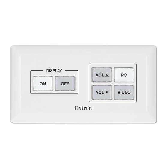
Page 13: Mlc 55 Rs And Mlc 55 Rs Vc Front Panels
RESET RESET MLC 55 RS MLC 55 RS VC Figure 4. MLC 55 RS and MLC 55 RS VC Front Panels Behind the Faceplates Display Power On and Off buttons Volume buttons (MLC RS 55) IR Learning sensor Volume control knob... -
Page 14: Mlc 55 Rs Eu Front Panel
MLC 55 RS EU Front Panel E E E RESET I I I VIDEO Figure 6. MLC 55 RS EU Front Panel Behind the Faceplate Display Power On and Off buttons Reset button IR Learning sensor Volume buttons Input Selection buttons... -
Page 15: Buttons
( < button), until released. NOTE: On the MLC 55 RS VC, you are not able to set any buttons to Volume mode. By default these two buttons are configured for input selection (see figure , on page 7). -
Page 16: Rear Panels
Wiring the Rear Panel Connectors on page 12 for connection information. MLC 55 RS MLC 55 RS VC Figure 7. MLC 55 RS MK Rear Panel Control port Power connector Volume control connector (MLC 55 RS VC only) MLC 55 Series MediaLink Controllers • Installation and Operation... - Page 17 Ne branchez pas l’alimentation au l’unité avant d’avoir lu les mises en garde ATTENTION de la page 15. Volume control connector (MLC 55 RS VC only) — Connect an Extron amplifier to this 3-pole, 3.5 mm captive screw connector to enable volume and mute control by the MLC (see...
-
Page 18: Wiring The Rear Panel Connectors
MLC 55 Rear Panel Figure 10. Connecting a Display Device to the RS-232 Port of an MLC 55 RS See the communication sheets for your device drivers for information on compatible baud rates and cabling type and distance. These communication sheets are accessed via the MLC configuration program and also at www.extron.com,... -
Page 19: Wiring For Ir Control
For IR control, there can be a maximum of 50 feet (15 m) between the IR port and the emitters. Example: Figure 13 shows a single IR emitter connected to the IR/S port of an MLC 55 RS or an MLC 55 RS VC. (15 m max) Ground (G) -
Page 20: Wiring The Volume Control Connector (Mlc 55 Rs Vc Only)
Wiring the Volume Control Connector (MLC 55 RS VC Only) Connect the remote volume control port of an Extron amplifier to the 3-pole captive screw connector on the rear panel of the MLC 55 volume control module, as shown in figure 14. -
Page 21: Connecting Power To The Mlc
Connecting Power to the MLC Notices for power connection CAUTION: Risk of electric shock. The wires must be kept separate while the power supply is plugged in. Remove power before wiring. ATTENTION : Risque de choc électrique. Les deux cordons d’alimentation doivent être tenus à... - Page 22 Plug the connector into the orange 2-pole captive screw power connector on the rear panel. In the example shown in figure 16, a power supply is being connected to the power connector of an MLC 55 RS. 12 VDC input...
-
Page 23: Removing And Replacing The Faceplate
US models only (see the Extron website for information on parts that are provided or available to order for each model). Black faceplate kits can also be ordered for US models (the MLC 55 RS VC kit also contains a black volume knob). Removing a Faceplate from an Unmounted Unit In order to connect and mount the MLC, you must remove the faceplate. -
Page 24: Placing The Faceplate Onto The Unit
MLC buttons and place the faceplate onto the mounted unit until its four corner magnets stick to the metal mounting plate. Removing and Replacing the MLC 55 RS VC Volume Knob The volume control knob is held in place by a magnet on the volume potentiometer. If... -
Page 25: Replacing Button Labels
Replacing Button Labels Kits containing additional printed labels can be ordered for the MLC at www.extron.com and inserted into the buttons on the unit. You can also download, free of charge, the Extron Button Label Generator software, which enables you to create your own button labels to print out and insert. -
Page 26: Connecting The Mlc To The Computer Usb Port
Connecting the MLC to the Computer USB Port The front panel USB mini-B port provides the means of configuring the MLC via the configuration program or SIS commands and to update the firmware. To connect the controller to the computer: Remove the faceplate (see Removing the Faceplate from a Mounted Unit page 17). - Page 27 Click . On the next screen, make sure that the Next Install the software radio button is selected, then click . (You do automatically (Recommended) Next not need to insert a disc.) Figure 22. Selecting the Radio Button to Install the USB Driver Automatically Your computer locates the driver needed for it to communicate with the MLC via the USB port.
-
Page 28: Ir Learning
NOTE: The MLC 55 RS and MLC 55 RS VC can be mounted to either a junction box (not included) or a mounting bracket (provided). The MLC 55 RS EU and MLC 55 RS MK can be mounted only in junction boxes. -
Page 29: Mounting The Mlc 55 To A Junction Box
MK External V I D Junction Box D I S MLC 55 RS MK t r o Faceplate Figure 25. Mounting an MLC 55 RS MK to an External Junction Box MLC 55 Series MediaLink Controllers • Installation and Operation... - Page 30 To mount an MLC 55 controller to a junction box: Mount the appropriate one-gang (MLC 55 RS and MLC 55 RS MK) or two-gang (MLC 55 RS VC and MLC 55 RS EU) junction box in the wall or furniture, following the directions provided with the box.
-
Page 31: Mounting An Mlc 55 Rs Or Mlc 55 Rs Vc To A Mud Ring
A one-gang or two-gang mounting bracket (“mud ring”) is provided with the MLC 55 RS and MLC 55 RS VC. If desired, you can mount the MLC to this type of bracket instead of a junction box (US models only). -
Page 32: Mounting The Mlc 55 Rs Eu In A Raceway
Figure 28. Mounting the MLC 55 RS EU in a Raceway To mount the MLC 55 RS EU in the raceway with the spacer: Mount a two-gang EU junction box in the raceway. Pull all cables through the junction box and spacer. -
Page 33: Locking The Front Panel (Executive Mode)
LED are located on the MLC front panel behind the faceplate (see Reset figure 29). On the MLC 55 RS, RS VC, and MK models, they are at the bottom of the unit, below the bottom two buttons. On the MLC 55 RS EU, they are located in the center of the unit, between the button and the volume buttons. - Page 34 You can perform two types of reset: • Resetting to the default configuration While the MLC is powered on, press and hold the button. The green Reset Reset LED lights and remains lit while the button is held. After 3 seconds, the Reset LED blinks once. Release the button, then immediately (within 1 second) press it again and release it immediately momentary press).
-
Page 35: Software-Based Configuration
Software-based Configuration This section describes basic procedures for setting up the MLC using the MLC 55, 62 and 64 Series Configuration Program. The following topics are covered: About the MLC 55, 62 and 64 Configuration Program • • Computer System Requirements •... -
Page 36: Downloading And Installing The Configuration
Downloading and Installing the Configuration Program The MLC 55, 62 and 64 Series Configuration Program can be downloaded free of charge from the Extron website. To obtain the MLC 55, 62 and 64 Series Configuration Program, download the program to your computer from the Extron website as follows: Go to the Extron website at www.extron.com... -
Page 37: Starting The Configuration Software
Select: Start All Programs\Extron Electronics\MLC 55, 62 and 64\MLC 55, 62 and 64 dialog box opens in front of the MLC 55, 62 and 64 Series Start Options Configuration Program main window. - Page 38 Select your MLC model from the drop-down menu. Select Model Figure 32. Add Device Dialog Box with Select Model Menu Displayed Click . The MLC 55, 62 and 64 Series main window opens, with the device name you entered displayed in the device configuration tree in the left panel ( Figure 33.
-
Page 39: Accessing The Help File
The configuration program main window consists of two major sections (see figure 33 on the previous page): Device configuration tree — Displays a list of devices that have been configured and lets you organize and save all configurations in a single project file. —... -
Page 40: Obtaining Device Drivers
(You can do this at any time while the program is open, regardless of whether a project has been created.) NOTE: Your computer must have an active internet connection to download drivers. Click Start\All Programs\Extron Electronics\MLC 55, 62 and 64\ or double-click the icon (shown at right) MLC 55, 62 and 64 MLC software on your desktop to launch the MLC configuration program application. - Page 41 dialog box opens. In the Driver Subscriptions Available Drivers panel, select the device types for which you will download drivers. Subscription Figure 37. Driver Subscription Dialog Box To select all device types available from a manufacturer, select the check box •...
- Page 42 Click . The dialog box opens, displaying Download Driver Subscriptions Download all drivers that have been selected or previously downloaded to your computer. Figure 38. Driver Subscription Download Screen If a driver on the list is new for your computer, it has the designation •...
-
Page 43: Downloading Drivers From The Web
Downloading Drivers from the Web Drivers can also be obtained directly from the Extron website without using the control program as follows: Visit the Extron website at www.extron.com, and click the tab (see Download figure 40, On the screen, click the link ( ) on the left Download... - Page 44 From the menu on the screen, select Extron Product Control System Drivers if it is not already selected. The other menus become available. MLC 55 Series Figure 41. Selecting MLC 55 Series from the Device Drivers Drop-down Menu From the rest of the menus on the screen, select search criteria for the drivers you want to download: From the menu, select...
- Page 45 Click on the device name whose driver you want to download. To download all the drivers in the current package, click the Download install for link. current driver package (Version n.n)(nnn.n MB) NOTE: The website may contain additional drivers that became available after the current driver package was created.
-
Page 46: Sis Control
SIS Control The MLC can be remotely controlled via a host computer or other control device that is attached to the MLC front panel USB port. You can issue Simple Instruction Set (SIS) commands to the MLC via the USB interface of your computer or control device with a communication software program such as Extron DataViewer or HyperTerminal. -
Page 47: Using The Command And Response Table
X! = Button number: Buttons are numbered from front panel top left ( ) to bottom right ( Button Configurations MLC 55 RS MLC 55 RS VC MLC 55 RS MK MLC 55 RS EU DISPLAY DISPLAY X@ = Button LED state (for white and red lighting) - Page 48 X1) = Device configuration compatibility version number (a 3-digit number listed to three decimal places: X1! = Device part number: • MLC 55 RS: 60-1390-02 • MLC 55 RS EU: 60-1390-33 • MLC 55 RS MK: 60-1390-23 • MLC 55 RS VC: 60-1391-02 MLC 55 Series MediaLink Controllers • SIS Control...
-
Page 49: Command And Response Table For Sis Commands
Command and Response Table for SIS Commands ASCII Command Response Command Additional Description (Host to Unit) (Unit to Host) Button Selection X! ] Trigger a button Execute the commands BTNO BtnoB* programmed to button . (This command produces the same results as pressing button the front panel). - Page 50 Ipn • X& X& default factory default name . For • MLC 55 RS • MLC 55 RS VC • MLC 55 RS EU • MLC 55 RS MK View unit name X^ ] Show the name ( ) of the MLC.
- Page 51 100. View controller part number X1! ] Show MLC part number MLC 55 RS: 60-1390-02 MLC 55 RS EU: 60-1390-33 MLC 55 RS MK: 60-1390-23 MLC 55 RS VC: 60-1391-02 X1@ ] View model name Show MLC model name •...
- Page 52 Extron Electronics makes no further warranties either expressed or implied with respect to the product and its quality, performance, merchantability, or fitness for any particular use. In no event will Extron Electronics be liable for direct, indirect, or consequential damages resulting from any defect in this product even if Extron Electronics has been advised of such damage.
Need help?
Do you have a question about the MLC 55 RS and is the answer not in the manual?
Questions and answers