
Related Manuals for Yamaha RCX221


Summary of Contents for Yamaha RCX221
- Page 1 YAMAHA 2-AXIS ROBOT CONTROLLER RCX221 User’s Manual ENGLISH YAMAHA MOTOR CO., LTD. IM Operations 882 Soude, Naka-ku, Hamamatsu, Shizuoka 435-0054.Japan URL http://www.yamaha-motor.jp/robot/index.html E100-Ver. 2.10...
-
Page 3: Introduction
Our sincere thanks for your purchase of this YAMAHA robot controller. This manual explains how to install and operate the YAMAHA robot controller. Be sure to read this manual carefully as well as related manuals and comply with their instructions for using the YAMAHA robot controller safely and correctly. -
Page 4: Before Using The Robot Controller (Be Sure To Read The Following Notes)
Before using the robot controller (Be sure to read the following notes) Please be sure to perform the following tasks before using the robot controller. Failing to perform these tasks may cause abnormal robot operation (vibration, noise) when the power is turned on. When connecting the power supply to the robot controller Always make a secure connection to the ground terminal on the robot controller to ensure safety and prevent malfunctions due to noise. -
Page 5: Overview Of The Rcx Series
YAMAHA robot models and simplifies maintenance. CE marking * As a YAMAHA robot series product, the RCX series robot controller is designed to conform to machinery directives, low-voltage directives and EMC (Electromagnetic compatibility) directives. In this case, the robot controller is set to operate under "SAFE"... - Page 6 MEMO...
-
Page 7: Table Of Contents
Make daily and periodic inspections 1-11 Warranty 1-11 Operating environment 1-11 Chapter 2 SYSTEM OVERVIEW System overview Main system configuration RCX22 series axis definition Part names and functions RCX221 (Maximum number of axes: 2) RCX221HP (Maximum number of axes: 2) - Page 8 Control system RCX221/RCX221HP Optional devices RPB programming box I/O expansion Regenerative unit Basic sequence from installation to operation 2-6 Chapter 3 INSTALLATION Unpacking Packing box Unpacking Installing the robot controller Installation conditions Installation methods Connector names Connecting to the power AC200 to 230V single-phase specifications 4.1.1...
- Page 9 11.2 Operation check 3-23 Chapter 4 OPERATION Operation overview The RCX robot controller Part names Main functions RPB programming box Part names Main functions Connection to the robot controller Changing the RPB screen settings Turning power on and off Operation keys RPB screen Operation key layout Basic key operation...
- Page 10 Switching the program 4-36 Changing the automatic movement speed 4-37 Executing the point trace 4-38 9.7.1 PTP motion mode 4-40 9.7.2 ARCH motion mode 4-41 9.7.3 Linear interpolation motion mode 4-43 Direct command execution 4-44 Break point 4-45 9.9.1 Setting break points 4-46 9.9.2 Deleting break points...
- Page 11 11.2 Displaying and editing point data 4-85 11.2.1 Point data input and editing 4-87 11.2.1.1 Restoring point data 4-88 11.2.2 Point data input by teaching 4-89 11.2.3 Point data input by direct teaching 4-91 11.2.4 Point jump display 4-92 11.2.5 Copying point data 4-93 11.2.6...
- Page 12 12.1.2 Axis parameters 4-155 12.1.3 Other parameters 4-174 12.1.4 Parameters for option boards 4-187 12.1.4.1 Option DIO setting 4-189 12.1.4.2 Serial IO setting 4-190 12.1.4.3 Setting the network parameters 4-195 12.2 Communication parameters 4-197 12.3 OPTION parameters 4-206 12.3.1 Setting the area check output 4-207 12.3.2 Setting the "SERVICE"...
- Page 13 14.5.1 Entering the password 4-270 14.5.2 Changing the access level 4-271 14.5.3 Displaying the Help message 4-272 Chapter 5 PARALLEL I/O INTERFACE Standard I/O interface overview ID setting Connector I/O signals Connector pin numbers Connecting the power supply 1.4.1 NPN/PNP power connector wiring Typical input signal connection Typical output signal connection 5-10...
- Page 14 Connecting to a PC 7-10 Chapter 8 SPECIFICATIONS Controller basic specifications Controller basic functions Controller external view RCX221 external view RCX221HP external view RPB basic specifications and external view Chapter 9 TROUBLESHOOTING Error Messages Robot controller error messages [ 0] Warnings and messages...
- Page 15 Chapter 1 USING THE ROBOT SAFELY Contents Safety information Particularly important cautions System design safety points Installation safety points Wiring safety points Start-up and maintenance safety points Safety precautions during robot operation Precautions for disposal Safety measures for robots Safety measures for single-axis robots, Cartesian robots, and pick &...
-
Page 17: Safety Information
1. Safety information Chapter Before using the YAMAHA robot controller, be sure to read this manual and related manuals, and follow their instructions to use the robot controller safely and correctly. Warnings and cautions listed in this manual relate to YAMAHA robot controllers. To ensure safety of the user's final system that includes YAMAHA robots and controllers, please take appropriate safety measures as required by the user's individual system. - Page 18 1. Safety information Use any of the following approaches to this manual when installing, operating and adjusting the YAMAHA robot and/or controller so that you can quickly refer to this manual Chapter when needed. 1. Keep the printed version of this manual (available for an additional fee) handy for ready reference.
-
Page 19: Particularly Important Cautions
System design safety points DANGER • YAMAHA ROBOT CONTROLLERS AND ROBOTS ARE DESIGNED AND MANUFACTURED FOR GENERAL-PURPOSE INDUSTRIAL EQUIPMENT. THEY SHOULD NOT BE USED IN THE FOLLOWING APPLICATIONS: • MEDICAL EQUIPMENT OR SYSTEMS WHICH WILL AFFECT HUMAN LIFE •... -
Page 20: Installation Safety Points
STARTING INSTALLATION OR WIRING WORK. FAILURE TO SHUT OFF ALL PHASES MAY CAUSE ELECTRICAL SHOCK OR PRODUCT DAMAGE. • YAMAHA ROBOTS AND ROBOT CONTROLLERS ARE NOT DESIGNED TO BE EXPLOSION-PROOF. DO NOT USE THEM IN LOCATIONS EXPOSED TO INFLAMMABLE GASES, GASOLINE OR SOLVENT THAT COULD CAUSE EXPLOSION OR FIRE. -
Page 21: Wiring Safety Points
2. Particularly important cautions Wiring safety points Chapter WARNING • ALWAYS SHUT OFF ALL PHASES OF THE POWER SUPPLY EXTERNALLY BEFORE STARTING INSTALLATION OR WIRING WORK. FAILURE TO SHUT OFF ALL PHASES MAY CAUSE ELECTRICAL SHOCK OR PRODUCT DAMAGE. CAUTION •... -
Page 22: Start-Up And Maintenance Safety Points
2. Particularly important cautions Start-up and maintenance safety points Chapter DANGER • NEVER ENTER THE ROBOT'S WORKING ENVELOPE WHILE THE ROBOT IS OPERATING OR THE MAIN POWER IS TURNED ON. FAILURE TO FOLLOW THIS INSTRUCTION MAY CAUSE SERIOUS ACCIDENTS INVOLVING INJURY OR DEATH. - Page 23 • IF A COMPONENT USED IN THE ROBOT OR CONTROLLER NEEDS TO BE REPLACED OR REPAIRED, ALWAYS FOLLOW THE INSTRUCTIONS FROM YAMAHA. INSPECTION AND MAINTENANCE OF THE CONTROLLER OR ROBOT BY ANY PERSON WHO DOES NOT HAVE THE REQUIRED KNOWLEDGE AND EXPERTISE IS DANGEROUS AND MUST BE AVOIDED.
-
Page 24: Safety Precautions During Robot Operation
2. Particularly important cautions • Do not use a hard or pointed object to operate the keys on the programming box. Malfunction or breakdown may result if the keys are Chapter damaged. Use your fi ngers to operate the keys. •... -
Page 25: Safety Measures For Robots
However, please check the robot model again when connecting it to the controller. 5. Warning labels and marks Warning labels The warning labels shown below are affixed to the controller. To use the YAMAHA robot and controller safely and correctly, be sure to observe the instructions and caution on the labels. -
Page 26: Warning Marks
6. Industrial robot operating and maintenance personnel Warning marks The following warning marks are shown on the controller. To use the YAMAHA robot Chapter and controller safely and correctly, be sure to observe the instructions and caution of the marks. -
Page 27: Make Daily And Periodic Inspections
7. Make daily and periodic inspections 7. Make daily and periodic inspections Chapter Always make sure that daily and periodic inspections are performed, and make a pre-work check to ensure there are no problems with the robot or related equipment. If a problem or abnormality is found, then promptly repair it or take other measures as necessary. - Page 28 9. Operating environment Storage humidity Storage humidity Below 95% RH (no condensation) Chapter The controller should be stored in a location at an ambient humidity below 95% RH (no condensation) when not being used. If the robot controller is stored in a location at high humidity for an extended period of time, rust may form on the electronic components in the robot controller.
- Page 29 Chapter 2 SYSTEM OVERVIEW Contents System overview Main system configuration RCX22 series axis definition Part names and functions RCX221 (Maximum number of axes: 2) RCX221HP (Maximum number of axes: 2) Control system RCX221/RCX221HP Optional devices RPB programming box I/O expansion...
-
Page 31: Main System Configuration
Chapter functions. Main system configuration Configuration 1: System for controlling one robot Example: MF50 ■ System for controlling one robot O P .1 RPB or RPB-E O P .2 YAMAHA robot... -
Page 32: Rcx22 Series Axis Definition
O P .1 RPB or RPB-E O P .2 YAMAHA robot RCX22 series axis definition The software for the RCX22 series is common to the RCX14 series and allows defining the main/sub robots and their axes. However, the RCX22 series basically does not require axis definition since it is a two-axis controller. -
Page 33: Part Names And Functions
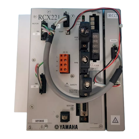
2. Part names and functions 2. Part names and functions RCX221 (Maximum number of axes: 2) ■ RCX221 front view Chapter OP.1 RGEN RCX221 MOTOR E-STOP TEMP ACIN OP.2 SAFETY EXT.E-STOP PIN11-12 SD/COM RCX221HP (Maximum number of axes: 2) ■ RCX221HP front view OP.1... -
Page 34: Control System
3. Control system 3. Control system The basic block diagram of the control system is shown below. RCX221/RCX221HP Chapter ■ Basic block diagram DRIVER2 BOARD ASSY X-axis motor Y-axis motor DRIVER2 BOARD ASSY Regenerative unit D.POWER BOARD ASSY AC200-230V XY axis motor... -
Page 35: Optional Devices
4. Optional devices 4. Optional devices RPB programming box The RPB is a hand-held device used to perform all robot operations, including manual Chapter operations, program input and editing, teaching and parameter settings. RPB-E Selector switch Emergency stop Emergency stop button button RPB-E (rear side) -
Page 36: Basic Sequence From Installation To Operation
5. Basic sequence from installation to operation 5. Basic sequence from installation to operation The basic sequence from installation to actual operation is shown below. Refer to this sequence to use the RCX22 series safely, correctly and effectively. Before beginning the work, read this user's manual thoroughly. Basic procedure Refer to: Chapter... - Page 37 Chapter 3 INSTALLATION Contents Unpacking Packing box Unpacking Installing the robot controller Installation conditions Installation methods Connector names Connecting to the power AC200 to 230V single-phase specifications 4.1.1 AC power connector wiring Power capacity Installing an external leakage breaker 3-10 Installing a circuit protector 3-11 Installing a surge absorber...
-
Page 39: Unpacking
The robot controller is high precision equipment and is carefully packed in a cardboard box to avoid shocks and vibrations. If there is any serious damage or dents on the packing box, please notify your YAMAHA sales dealer without unpacking the box. Chapter... -
Page 40: Installing The Robot Controller
2. Installing the robot controller 2. Installing the robot controller When installing, choose a proper place for your robot controller, taking into account your system layout, accessibility for maintenance, etc. Installation conditions Chapter CAUTION (1) When carrying the robot controller, use a dolly or similar hand truck and move it carefully to avoid dropping and resultant damage. - Page 41 2. Installing the robot controller ■ Clearance for installing the controller 50mm or more OP.1 RGEN RCX221 Chapter E-STOP MOTOR TEMP 50mm 50mm or more or more ACIN OP.2 SAFETY EXT.E-STOP PIN11-12 SD/COM 17mm or more When installing the robot controller, follow the precautions below.
-
Page 42: Installation Methods
2. Installing the robot controller Installation methods There are three methods for installing the robot controller as explained below. 1) Using the rubber feet (attached as standard parts) ■ Using the rubber feet Chapter O P. 1 O P. 2 2) Attaching the L-type brackets (supplied as standard accessories) to the front ■... - Page 43 2. Installing the robot controller 3) Attaching the L-type brackets (supplied as standard accessories) to the rear ■ Attaching the L-type brackets to the rear Chapter O P. 1 O P. 2 L-type bracket part No. (single item) Standard (for front and rear) KAS-M410H-000 When attaching an L-type bracket to the top and bottom of the controller, use two same brackets for one controller.
-
Page 44: Connector Names
3. Connector names 3. Connector names Connector names, locations and functions are shown below. ■ RCX connectors OP.1 RGEN RCX221 RGEN Chapter MOTOR E-STOP TEMP ROB I/O TEMP OP.1 ACIN ACIN OP.2 SAFETY SAFETY EXT.E-STOP PIN11-12 OP.2 SD/COM WARNING TO PREVENT ELECTRICAL SHOCKS, NEVER TOUCH THE RGEN AND AC IN TERMINALS WHEN POWER IS SUPPLIED TO THE ROBOT CONTROLLER. -
Page 45: Connecting To The Power
4. Connecting to the power 4. Connecting to the power Attach the power connector to the power cable and insert it into the "AC IN" connector on the front panel of the controller as shown below. AC200 to 230V single-phase specifications Chapter CAUTION Before connecting the power cable, be sure to check that the power supply... -
Page 46: Ac Power Connector Wiring
4. Connecting to the power 4.1.1 AC power connector wiring ● Length of exposed wire lead Strip the wire to expose 8 to 9 mm of bare lead. 8 to 9 mm Chapter ● Wiring Insert the wire lead into the opening in the power connector in either of the following methods, and make sure the wire is securely attached. -
Page 47: Power Capacity
4. Connecting to the power Power capacity The required power capacity depends on the robot model and the number of axes to be controlled. CAUTION The power supply voltage for the robot controller must always be regulated within ±10%. If the voltage drops, the robot controller may issue an abnormal Chapter voltage alarm causing the robot to trigger emergency stop. -
Page 48: Installing An External Leakage Breaker
4. Stray capacitance between the cable and FG may vary depending on the cable installation condition, causing the leakage current to fl uctuate. Leakage current RCX221 control power supply (L1, N1) 1mA in total RCX221 main power supply (L, N) -
Page 49: Installing A Circuit Protector
DOWN WHILE THE ROBOT CONTROLLER IS USED WITHOUT INSTALLING A CIRCUIT PROTECTOR. Rated current Operating characteristics RCX221 control power supply (L1, N1) Slow type with inertial delay RCX221 main power supply (L, N) Installing a surge absorber Be sure to install an external surge absorber to protect the equipment from surge noise caused by lightning strikes. -
Page 50: Installing A Current Control Switch
4. Connecting to the power Installing a current control switch When controlling the power on/off of the robot controller from an external device, the main power supply and control power supply paths must be separated from each other. When controlling the power on/off by emergency stop, the main power supply must be turned on or off. -
Page 51: Connecting The Robot Cables
Before turning on the controller, make sure again that the cables are securely connected. Also make sure that the robot is properly grounded. For details on the grounding method, refer to the robot user's manual. ■ Robot cable connection O P. 1 O P. 2 Connected to YAMAHA robot 3-13... -
Page 52: Connecting The Rpb Programming Box
O P .1 RPB programming box O P .2 ● Connecting a terminator If not connecting the RPB, plug the terminator (supplied) into the RPB connector. ■ Connecting a terminator OP.1 RGEN RCX221 MOTOR E-STOP TEMP ACIN OP.2 O P .2 SAFETY EXT.E-STOP... -
Page 53: I/O Connections
7. I/O connections 7. I/O connections The various input/output (I/O) signals from peripheral equipment can be connected to the robot controller. Each I/O is set with a number, and the I/O connector to be used depends on that number. For more detailed information on inputs and outputs, see Chapter 5, "Parallel I/O interface" or see Chapter 6, "SAFETY I/O interface". -
Page 54: Connecting A Host Computer
For more detailed information on the RS-232C interface, see "RS-232C Interface" in Chapter Chapter 7. NOTE D-SUB 9P (female) connector is for RS-232C interface. ■ Host computer connection OP.1 RGEN RCX221 MOTOR E-STOP Straight serial conversion adapter (option) TEMP ACIN 9 pins 9 pins OP.2... -
Page 55: Connecting A Regenerative Unit
The regenerative unit is attached to the right side of the controller prior to shipping. NOTE • The RCX221 may require a regenerative unit depending on the robot Chapter type to be connected. • Check the cable and connectors for bent pins, kinks, and other damage before connecting. - Page 56 9. Connecting a regenerative unit ■ Regenerative unit block diagram Regenerative unit RCX221 RGEN TEMP Chapter Thermal sensor (normally closed) Standard cable length: 300mm CAUTION (1) The generative unit becomes hot during operation. Do not touch it to avoid burns.
-
Page 57: Precautions For Cable Routing And Installation
10. Precautions for cable routing and installation 10. Precautions for cable routing and installation 10.1 Wiring methods Various cables are used to connect the robot controller to peripheral devices. Follow the precautions below when making cable routing and connections to avoid malfunctions due to noise. - Page 58 10. Precautions for cable routing and installation Refer to the drawing below when making the cable connections. ■ Cable connection DIO cable Chapter OP.1 RGEN RCX221 MOTOR E-STOP TEMP ACIN OP.2 SAFETY EXT.E-STOP PIN11-12 SD/COM SAFETY cable 3-20...
-
Page 59: Precautions For Installation
10. Precautions for cable routing and installation 10.2 Precautions for installation This robot controller is not designed with an explosion-proof, dust-proof or drip-proof structure. Do not install it in the following locations or environments (1) where exposed to flammable gases or liquids. (2) where conductive debris such as metal cutting chips are spread. -
Page 60: Checking The Robot Controller Operation
SAFETY connector.) The connection status of emergency stop input signal is described in detail in Chapter 6, "SAFETY I/O interface". 11.1 Cable connection ■ Cable connection O P .1 O P .2 SAFETY connector YAMAHA robot (supplied) 3-22... -
Page 61: Operation Check
11. Checking the robot controller operation 11.2 Operation check After connecting the robot and special connector (supplied) to the controller, turn on the power to the controller and check the following points. Normal operation • The "RDY" and "SRV" LED lamps on the front panel of the controller light up. The "ERR"... - Page 62 MEMO 3-24...
- Page 63 Chapter 4 OPERATION Contents Operation overview The RCX robot controller Part names Main functions RPB programming box Part names Main functions Connection to the robot controller Changing the RPB screen settings Turning power on and off Operation keys RPB screen Operation key layout Basic key operation 4-10...
- Page 64 "AUTO" mode 4-28 Automatic operation 4-31 Stopping the program 4-32 Resetting the program 4-33 Switching task display 4-35 Switching the program 4-36 Changing the automatic movement speed 4-37 Executing the point trace 4-38 9.7.1 PTP motion mode 4-40 9.7.2 ARCH motion mode 4-41 9.7.3 Linear interpolation motion mode...
- Page 65 10.3.4 Copying a program 4-67 10.3.5 Erasing a program 4-68 10.3.6 Renaming a program 4-69 10.3.7 Changing the program attribute 4-70 10.3.8 Displaying object program information 4-71 10.3.9 Creating a sample program automatically 4-72 10.4 Compiling 4-74 10.5 Line jump and character string search 4-75 10.6 Registering user function keys 4-75...
- Page 66 11.5.2 Editing the shift coordinate range 4-119 11.5.2.1 Restoring a shift coordinate range 4-121 11.5.3 Shift coordinate setting method 1 4-122 11.5.4 Shift coordinate setting method 2 4-125 11.6 Displaying, editing and setting hand definitions 4-128 11.6.1 Editing hand definitions 4-131 11.6.1.1 Restoring hand definitions 4-132...
- Page 67 12.4.5 System generation 4-236 12.5 Self diagnosis 4-237 12.5.1 Controller check 4-238 12.5.2 Error history display 4-239 12.5.3 Displaying the total operation time 4-240 12.5.4 System error details display 4-241 12.6 Backup processes 4-242 12.6.1 SD memory card 4-243 12.6.1.1 Loading files 4-245 12.6.1.2 Saving files 4-247...
-
Page 69: Operation Overview
1. Operation over view 1. Operation over view The controller configuration and main functions are shown below. Set up the equipment as needed according to the operation to be performed. CAUTION The external circuit connected to the robot controller should be prepared by the user. -
Page 70: The Rcx Robot Controller
2. The RCX robot controller 2. The RCX robot controller Part names Controller front panel ■ Part names and layout OP.1 RGEN “SRV”LED RCX221 “ERR”LED Chapter E-STOP MOTOR “RDY”LED TEMP E-STOP “E-STOP”LED ACIN AC IN terminal RPB connector OP.2 SAFETY EXT.E-STOP... -
Page 71: Main Functions
3. RPB programming box 3. RPB programming box The RPB programming box connects to the robot controller and is used to edit and execute robot programs. Part names ■ Programming box Selector switch Chapter Display (liquid crystal screen) (RPB-E only) Emergency stop button Sheet key Rear view... -
Page 72: Connection To The Robot Controller
Emergency stop is triggered when the RPB is connected to or disconnected from the robot controller while the power is on. If this happens, emergency stop must be cancelled to continue operation. ■ Robot controller connection OP.1 RGEN RCX221 E-STOP MOTOR TEMP RPB programming box ACIN RPB connector OP.2... -
Page 73: Changing The Rpb Screen Settings
3. RPB programming box Changing the RPB screen settings The RPB screen contrast can be adjusted, and the key-press volume can be changed as needed. 1) Turn on the power while holding down on the RPB. The RPB setting screen ("ADJUST" mode) appears. ■... -
Page 74: Turning Power On And Off
4. Turning power on and off 4. Turning power on and off This section explains how to turn power on and off, assuming that the external emergency stop circuit and other necessary units are connected according to the instructions in Chapter 3, "Installation", and also that the robot controller operates correctly. - Page 75 4. Turning power on and off 4) After the power is turned on, return-to-origin must be performed before starting robot operation. Then start the robot operation. Refer to "11.8 Return-to-origin" in this chapter for how to perform return-to-origin. ■ "MANUAL" mode screen MANUAL 50% [MG][S0H0J] –––––––––––––––––––––––––––––––––––––––––––––––––––––...
-
Page 76: Operation Keys
5. Operation keys 5. Operation keys RPB screen The RPB screen display is composed of 4 areas as shown below. ■ RPB screen example 1st line ...System line PROGRAM>EDIT <TEST1 > 2nd line ...Message line 3rd line '***** TEST1 PROGRAM ***** Chapter 4th line ...Data area... -
Page 77: Operation Key Layout
5. Operation keys Operation key layout The operation keys are covered with a plastic sheet to prevent dust. There are 3 main kinds of keys. 1) Function keys 2) Control keys 3) Data keys ■ Sheet key layout Chapter Function key Data key Control key... -
Page 78: Basic Key Operation
5. Operation keys Basic key operation 1) Each operation key has 3 different functions as shown below. as needed to enable various functions. ■ Key configuration Shift 1 Shift 2 Shift 3 Chapter 2) There are 3 ways (shift 1 to shift 3) to use each operation key. Shift Example of key input Input data... -
Page 79: Function Keys
5. Operation keys Function keys To operate the RPB, select the menus by pressing the function keys. The relation of the function keys to their menus in "MANUAL" mode is shown below. Function key Selected menu (F1) POINT (F2) PALLET Chapter (F3) ORIGIN... - Page 80 5. Operation keys Relation of function keys to menus ■ Function keys and menus MANUAL 50%[MG][S0H0J] Current position 0 *M2= POINT PALLET ORIGIN VEL+ VEL- Chapter [F1] [F2] [F3] [F4] [F5] SHIFT HAND UNITCHG VEL++ VEL— [F6] [F7] [F8] [F9] [F10] ...UPPER COORDI...
-
Page 81: Control Keys
5. Operation keys Control keys There are 6 kinds of control keys: (1) Mode selection keys, (2) Extended function keys, (3) Cursor keys, (4) Page keys, (5) Edit keys, (6) Jog keys. The functions of each key are explained below. Mode selection keys : Displays the mode menu (highest hierarchy). - Page 82 5. Operation keys Edit keys These keys are enabled when the editing cursor is displayed. : Toggles between "Insert" and "Overwrite" modes. The cursor "_" appears in "Overwrite" mode and " ■ " appears in "Insert" mode. : Deletes one character at the cursor position. : Inserts one line at the cursor position.
-
Page 83: Data Keys
5. Operation keys Data keys The data keys are used for data input, programming and data editing. There are 2 kinds of data keys. Alphanumeric keys : Enters numbers. : Enters alphabetic characters. Chapter : Inserts spaces. Symbol keys Other keys Enter key : Pressing this key executes a direct command when in "AUTO >... -
Page 84: Emergency Stop
6. Emergency stop 6. Emergency stop If for some reason you want to stop the robot immediately during operation, press the emergency stop button on the RPB. Pressing the emergency stop button cuts off power to the robot to stop operation. A message appears on the RPB screen as shown below. The highlighted display for the mode name is cancelled during emergency stop. -
Page 85: Emergency Stop Reset
6. Emergency stop Emergency stop reset To return to normal operation after emergency stop, emergency stop must be reset. NOTE • Emergency stop can also be triggered by an emergency stop input from the SAFETY I/O interface. To cancel this emergency stop, refer to Chapter 6. •... - Page 86 6. Emergency stop 4) Press (MOTOR). The following screen appears. ■ "UTILITY>MOTOR" mode (1) UTILITY>MOTOR motor power: Off D1=M1: Brake D5=M5: no axis D2=M2: Brake D6=M6: no axis Chapter D3=M3: no axis D4=M4: no axis 5) Press (On) to turn on the motor power. At the same time, the servomotor sets to HOLD status.
-
Page 87: Mode Configuration
7. Mode configuration 7. Mode configuration The robot operation mode consists of the following modes. Basic operation modes “SERVICE” mode “DI/DO “AUTO” “MANUAL” “PROGRAM” “SYSTEM” “UTILITY” monitor” mode mode mode mode mode Chapter mode "SERVICE" mode can be used only when "SAFE" mode is enabled. Basic operation modes Robot operation is classified into 5 basic modes as follows. -
Page 88: Other Operation Modes
Use this mode to monitor the robot controller I/O status or task status on the RPB screen. Use to select this mode. "UTILITY" mode Use this mode to perform maintenance of the YAMAHA robots such as recovery from emergency stop and motor servo on/off switching. Use to select this mode. 4-20... -
Page 89: Mode Hierarchy
7. Mode configuration Mode hierarchy Robot operation is mainly performed by pressing the function keys to select the desired mode from the menu. (Refer to the "Mode hierarchy diagram" described later.) When the controller is turned on, the "MANUAL" mode menu first appears on the screen. Pressing displays the 4 basic modes on the guideline (bottom line) of the screen as shown below. - Page 90 7. Mode configuration Functions are switched with the shift keys. The menu display changes while this shift key is pressed. ■ Shift keys ■ Function switching RESET TASK VEL+ VEL- Chapter [F1] [F2] [F3] [F4] [F5] POINT DIRECT BREAK VEL++ VEL-- [F6] [F7]...
- Page 91 7. Mode configuration NOTE • When the data is being edited such as in "EDIT" mode, inoperative. After pressing to return the mode hierarchy, press • From here in this user's manual the mode hierarchy status is stated in the order as shown below.
- Page 92 7. Mode configuration ■ Mode hierarchy diagram F1 AUTO F1 PTP/ARCH/LINEAR F1 RESET F2 ARCHPOS (when F1 is ARCH) F2 TASK F3 JUMP F3 DIR F4 VEL+ F4 VEL+ F5 VEL- F5 VEL- F6 A.AXIS+ (when F1 is ARCH) F7 A.AXIS- (when F1 is ARCH) F8 UNITCHG F9 VEL++ F6 POINT...
- Page 93 7. Mode configuration F3 MANUAL F1 EDIT F6 SHIFT F4 VEL+ F2 RANGE F5 VEL- F4 VEL+ F8 UNITCHG F5 VEL- F9 VEL++ F6 METHOD1 F10 VEL-- F4 VEL+ F5 VEL- F7 METHOD2 F8 UNITCHG F9 VEL++ F9 VEL++ F10 VEL-- F7 HAND F10 VEL-- F1 EDIT...
-
Page 94: Service" Mode
8. "SERVICE" mode 8. "SERVICE" mode "SERVICE" mode can be used only when "SAFE" mode is enabled. Use "SERVICE" mode to perform safe maintenance work with the RPB while within the safety enclosure of the robot system. This mode can be selected by turning DI02 ("SERVICE" mode input) OFF. -
Page 95: Limitations On Robot Operating Speed
8. "SERVICE" mode Limitations on robot operating speed A major purpose of robot operation while the operator is working within the safety enclosure is maintenance and adjustment of the robot. If a dangerous situation should occur, the operator can easily avoid it if the robot operating speed is maintained within 250mm/sec. -
Page 96: Auto" Mode
9. "AUTO" mode 9. "AUTO" mode "AUTO" mode executes robot language programs and related tasks. The initial "AUTO" mode screen is shown below. ■ "AUTO" mode Automatic movement speed Program name Mode hierarchy Task display Message line Online command AUTO [T1] 100% <TEST1 >... - Page 97 9. "AUTO" mode Pointer display The program line number to be executed next is shown highlighted in the program listing. Guideline The contents assigned to function keys are shown highlighted. A message on what to do next also appears here in some operation steps. Upon entering "AUTO"...
- Page 98 9. "AUTO" mode Valid keys and submenu descriptions in "AUTO" mode are shown below. Valid keys Menu Function Cursor key Scrolls the program listing. ( ↑ / ↓ ) Page key Switches to other screens. RESET Resets the program. TASK Changes the program listing according to each task.
-
Page 99: Automatic Operation
9. "AUTO" mode Automatic operation Program commands are executed continuously during automatic operation. Before starting automatic operation, make sure that return-to-origin, program debugging, I/O signal connections and point data teaching have already been completed. When the execution level is set to other than level 0, automatic operation is possible even if return-to-origin is incomplete. -
Page 100: Stopping The Program
9. "AUTO" mode The following keys are enabled during automatic operation. Valid keys Menu Function Increases automatic movement speed for the selected VEL++ robot group in 5% increments. Decreases automatic movement speed for the selected VEL-- robot group in 5% decrements. ROBOT Switches the selected robot group. -
Page 101: Resetting The Program
9. "AUTO" mode Resetting the program To restart a program stopped with from the beginning, reset the program. NOTE The output is also reset when the program is reset. However, the output will not be reset when a sequence program is being executed without selecting "RST.DO"... - Page 102 9. "AUTO" mode • When the program "_SELECT" exists: 1) Press (RESET) in "AUTO" mode. The following message appears on the guideline when "_SELECT" exists among the programs. Press (YES) to reset the selected program by switching it to "_SELECT", or press (NO) to just reset the current program.
-
Page 103: Switching Task Display
9. "AUTO" mode Switching task display When a program executing multiple tasks is stopped, the program listing for each task can be displayed. [Procedure] 1) Press during program execution to stop the program. Chapter 2) Press to display the program listing. The pointer indicates the next command line number to be executed in the current task. -
Page 104: Switching The Program
9. "AUTO" mode Switching the program If the program displayed on the screen is not the one you want to execute, it can be switched to another program. NOTE The output is also reset when the program is reset. However, the output will not be reset when a sequence program is being executed without selecting "RST.DO"... -
Page 105: Changing The Automatic Movement Speed
9. "AUTO" mode Changing the automatic movement speed Automatic movement speed for the selected robot group can be set within the range of 1 to 100%. NOTE Automatic movement speeds once set here are stored in the internal memory even when the power is turned off. If the speed is set with the program command statement (SPEED statement), the actual robot operating speed will be the product of that speed and the Chapter... -
Page 106: Executing The Point Trace
9. "AUTO" mode Executing the point trace Point data positions can be checked by actually moving the robot arm in the following modes. • PTP motion mode • Arch motion mode • Linear interpolation motion mode (Linear interpolation motion at the sub robot is not supported in controller versions prior to Ver. - Page 107 9. "AUTO" mode Valid keys and submenu descriptions in "AUTO > POINT" mode are shown below. Valid keys Menu Function Cursor key Switches the point number and scrolls the screen. ( ↑ / ↓ ) Page key Switches to other screens. PTP/ ARCH/ Switches the trace movement mode.
-
Page 108: Ptp Motion Mode
9. "AUTO" mode 9.7.1 PTP motion mode [Procedure] 1) Press in "AUTO>POINT" mode to display a screen like that shown below, then press (PTP) to select the PTP motion mode. ■ Point trace screen in PTP motion mode (1) Chapter AUTO >POINT 100% [MG][S0H0J]... -
Page 109: Arch Motion Mode
9. "AUTO" mode 9.7.2 ARCH motion mode [Procedure] 1) Press in "AUTO>POINT" mode to display a screen like that shown below, then press (ARCH). ■ Point trace screen in ARCH motion mode (1) Chapter AUTO>POINT 100% [MG][S0H0J] ————————————x———————y———————z———————r——— 150.50 64.53 0.00 0.00 96.65 -224.89... - Page 110 9. "AUTO" mode NOTE Enter the number of pulses for the Y-axis. 4) Use the cursor ( ↑ / ↓ ) keys to select the point number to be checked. 5) Press to move the robot by arch motion to the specified point position. The trace speed is one fifth of the automatic movement speed.
-
Page 111: Linear Interpolation Motion Mode
9. "AUTO" mode 9.7.3 Linear interpolation motion mode [Procedure] 1) Press in "AUTO>POINT" mode to display a screen like that shown below, then press (LINEAR). ■ Point trace screen in linear interpolation motion mode (1) Chapter AUTO >POINT 100% [MG][S0H0J] ————————————x———————y———————z———————r———... -
Page 112: Direct Command Execution
9. "AUTO" mode Direct command execution In "AUTO>DIRECT" mode, one line of the command statement can be executed just after you have entered it. [Procedure] 1) Press (DIRECT) in "AUTO" mode. The screen switches to "AUTO>DIRECT" mode and the cursor appears on the screen. The prompt (>) also appears on the bottom line of the screen. -
Page 113: Break Point
9. "AUTO" mode Break point An ongoing program can be stopped if a break point is set in the program. This is useful when debugging the program. The program execution pauses on the line just prior to a break point. The program execution will restart from the break point when is pressed. -
Page 114: Setting Break Points
9. "AUTO" mode 9.9.1 Setting break points To make program debugging easy, the program execution can be stopped on the line where a break point is set. [Procedure] 1) Press (BREAK) in "AUTO" mode to switch to "AUTO>BREAK" mode. 2) Use the cursor keys to select the line number on which a break point is to be set. Chapter 3) Press (SET). -
Page 115: Deleting Break Points
9. "AUTO" mode 9.9.2 Deleting break points Break points can be deleted. Press (SEARCH) as needed to find a break point that was set. [Procedure] 1) Use the cursor ( ↑ / ↓ ) keys to select the line number where the break point is set. 2) Press (CANCEL). -
Page 116: Executing A Step
9. "AUTO" mode 9.10 Executing a step WARNING THE ROBOT MAY BEGIN TO MOVE WHEN STEP IS EXECUTED. TO AVOID DANGER, DO NOT ENTER THE ROBOT MOVEMENT RANGE. [Procedure] 1) Press (STEP) in "AUTO" mode. Chapter 2) Each time this key is pressed, the command statement of the highlighted line number is executed. -
Page 117: Executing The Next Step
9. "AUTO" mode 9.12 Executing the next step WARNING THE ROBOT MAY BEGIN TO MOVE WHEN NEXT IS EXECUTED. TO AVOID DANGER, DO NOT ENTER THE ROBOT MOVEMENT RANGE. [Procedure] 1) Press (NEXT) in "AUTO" mode. Chapter 2) Each time this key is pressed, the command statement of the highlighted line number is executed. -
Page 118: Program" Mode
10. "PROGRAM" mode 10. "PROGRAM" mode Robot language programs can be edited, deleted and managed in "PROGRAM" mode. The initial "PROGRAM" mode screen is shown below. When "PROGRAM" mode is entered, the currently selected program appears on the screen. ■ "PROGRAM" mode Online command Mode hierarchy Message line... -
Page 119: Scrolling A Program Listing
10. "PROGRAM" mode Valid keys and submenu descriptions in "PROGRAM" mode are shown below. Valid keys Menu Function Cursor key Selects the program and scrolls the screen. ( ↑ / ↓ ) Page key Switches the page display. EDIT Edits the program. Displays the program data. -
Page 120: Program Editing
10. "PROGRAM" mode 10.2 Program editing [Procedure] 1) Press (EDIT) in "PROGRAM" mode. A cursor appears on the top line of a program listing as shown below, allowing program editing. 2) Use the cursor keys to move the cursor to the position to be edited and enter a Chapter program command with the RPB. - Page 121 10. "PROGRAM" mode Valid keys and submenu descriptions in "PROGRAM > EDIT" mode are shown below. Valid keys Menu Function Cursor key Moves the cursor and scrolls the screen. ( ↑ / ↓ ) Page key Switches the page display. Switches between Insert and Overtype modes.
-
Page 122: Cursor Movement
10. "PROGRAM" mode 10.2.1 Cursor movement [Procedure] 1) Pressing the cursor ( ↑ / ↓ ) keys in "PROGRAM>EDIT" mode moves the cursor up or down one line at a time. Pressing the cursor ( ← / → ) keys moves the cursor right or left one character at a time. 2) Pressing the page ( ) key moves the cursor one page Chapter... -
Page 123: Insert/Overwrite Mode Switching
10. "PROGRAM" mode 10.2.2 Insert/Overwrite mode switching [Procedure] 1) Press in "PROGRAM > EDIT" mode. The cursor changes to underline ( _ ) form, and the screen switches to Insert mode. In Insert mode, the input character is inserted just previous to the cursor position. ■... -
Page 124: Inserting A Line
10. "PROGRAM" mode 10.2.3 Inserting a line [Procedure] Pressing ) in "PROGRAM > EDIT" mode inserts a blank line at the line previous to the cursor position. ■ Inserting a line PROGRAM >EDIT <TEST2 > ——————————————————————————————————————————— Chapter 3 DO2(0)=0 4 WAIT DI3(4,3,2)=3 6 MOVE P,P0 ’ORIGIN 7 MOVE P,P1... -
Page 125: User Function Key Display
10. "PROGRAM" mode 10.2.6 User function key display User function keys make it easier to enter programs. NOTE When using this function, it is necessary to make a program named "FUNCTION" and then write command statements for registering functions. For information on how to register the function keys, refer to "10.3.9 Creating a sample program automatically"... -
Page 126: Quitting Program Editing
10. "PROGRAM" mode 10.2.7 Quitting program editing Press to quit program editing in "PROGRAM>EDIT" mode. 10.2.8 Specifying the copy/cut lines [Procedure] 1) In "PROGRAM>EDIT" mode, move the cursor to the line you want to copy or cut. Chapter 2) Press (SELECT) to select the line. -
Page 127: Copying The Selected Lines
10. "PROGRAM" mode 10.2.9 Copying the selected lines [Procedure] After selecting the lines in "10.2.8", press (COPY). The data on the selected lines are copied into the buffer. The " " marks then disappear. ■ Copying the selected lines PROGRAM >EDIT <TEST2 >... -
Page 128: Pasting The Data
10. "PROGRAM" mode 10.2.11 Pasting the data [Procedure] When (PASTE) is pressed in "PROGRAM>EDIT" mode, the data stored into the buffer by copy/cut operation is inserted just before the cursor line. ■ Pasting the data PROGRAM >EDIT <TEST2 > ——————————————————————————————————————————— Chapter 1 ’***** TEST2 PROGRAM ***** 2 ’... -
Page 129: Line Jump
10. "PROGRAM" mode 10.2.13 Line jump [Procedure] 1) In "PROGRAM>EDIT" mode, press (JUMP) to enter "PROGRAM>EDIT>JUMP" mode. The message "Enter line no. > " appears on the guideline. ■ Line jump Chapter PROGRAM >EDIT <TEST2 > ——————————————————————————————————————————— 1 ’***** TEST2 PROGRAM ***** GOTO *_’... -
Page 130: Searching A Character String
10. "PROGRAM" mode 10.2.14 Searching a character string [Procedure] 1) In "PROGRAM>EDIT" mode, press (FIND) to enter "PROGRAM>EDIT>FIND" mode. The message "Character string >" appears on the guideline. 2) Enter the character string you want to search for and press Chapter A maximum of 20 characters can be used. -
Page 131: Directory
10. "PROGRAM" mode 10.3 Director y When (DIR) is pressed in "PROGRAM" mode, information on each program appears as shown below. NOTE A maximum of 100 programs can be stored. ■ Program information (1) Chapter PROGRAM >DIR <TEST1 > Name Line Byte RW/RO... - Page 132 10. "PROGRAM" mode Contents of each item are shown below. Item Description Indicates the serial number of the program. The number of the program which is currently selected is highlighted (reversed background). Indicates the program name. The " * " mark (reversed background) shows this Name program is compiled and the object program exists.
-
Page 133: Cursor Movement
10. "PROGRAM" mode 10.3.1 Cursor movement [Procedure] To select the program, use the cursor ( ↑ / ↓ ) keys in "PROGRAM>DIR" mode. The pointer cursor moves to the selected program number. The program name is displayed at the right end on the system line (1st line). 10.3.2 Registering a new program name When creating a new program, you must first register the program name. -
Page 134: Directory Information Display
10. "PROGRAM" mode 10.3.3 Director y information display [Procedure] In "PROGRAM>DIR" mode, press (INFO) to enter "PROGRAM>DIR>INFO" mode. The following information on the selected program appears. ■ Program information PROGRAM >DIR>INFO <TEST1 > Chapter Source(use/sum) 1316/364580 bytes Object(use/sum) 528/ 98304 bytes Sequence(use/sum) 4096 bytes Number of program... -
Page 135: Copying A Program
10. "PROGRAM" mode 10.3.4 Copying a program A program in the directory can be copied under a different name. NOTE Program names can be up to 8 characters and consist of a combination of alphanumeric characters (0 to 9, A to Z) and underscores ( _ ). [Procedure] 1) In "PROGRAM>DIR"... -
Page 136: Erasing A Program
10. "PROGRAM" mode 10.3.5 Erasing a program Unnecessary programs in the directory can be erased. CAUTION • Programs with an "RO (read only)" attribute cannot be erased. When these programs must be erased, change the attribute. • To change the program attribute, refer to "10.3.7 Changing the program attribute". -
Page 137: Renaming A Program
10. "PROGRAM" mode 10.3.6 Renaming a program To change the names of programs in the directory, proceed as follows. [Procedure] 1) In "PROGRAM>DIR" mode, use the cursor ( ↑ / ↓ ) keys to select the program to be renamed. 2) Press (RENAME) to enter "PROGRAM>DIR>RENAME"... -
Page 138: Changing The Program Attribute
10. "PROGRAM" mode 10.3.7 Changing the program attribute Editing and erasing the programs can be prohibited by specifying the program attribute. There are two program attributes: RW and RO. Each time a change is made a program attribute is alternately switched. 1. -
Page 139: Displaying Object Program Information
10. "PROGRAM" mode 10.3.8 Displaying object program information To display information on an executable object program, proceed as follows. [Procedure] 1) Press (OBJECT) to enter "PROGRAM>DIR>OBJECT" mode. 2) Object information appears as shown below. ■ Object program information Chapter PROGRAM >DIR>OBJECT <TEST2 >... -
Page 140: Creating A Sample Program Automatically
10. "PROGRAM" mode 10.3.9 Creating a sample program automatically This section explains the procedure of automatically creating a sample program for defining user function keys which can be used in "MANUAL" and "PROGRAM" modes. NOTE Use caution when creating a sample program automatically, since previously defi... - Page 141 10. "PROGRAM" mode [Sample program listing] *** <FUNCTION> SAMPLE PROGRAM **** '*You can change any statements '*as you like. '*<FUNCTION> will help you in '*MANUAL and PROGRAM mode. '********************************************************* *M_F1:'DO(20)ALTERNATE DO(20)=~DO(20) *M_F2:'DO(21)ALTERNATE DO(21)=~DO(21) *M_F3:'DO(22)ALTERNATE Chapter DO(22)=~DO(22) *M_F4:'DO(23)ALTERNATE DO(23)=~DO(23) *M_F5:'DO(24)ALTERNATE DO(24)=~DO(24) *M_F6:'DO(25)MOMENTARY DO(25)=1 DO(25)=0...
-
Page 142: Compiling
10. "PROGRAM" mode 10.4 Compiling To compile the program and create an executable object program, follow the procedure below. The object program allows you to check input errors or bugs after program editing. NOTE Even if the specifi ed program is yet not compiled, it is compiled automatically when you move to "AUTO"... -
Page 143: Line Jump And Character String Search
10. "PROGRAM" mode 10.5 Line jump and character string search (JUMP), (FIND), (FIND+) and (FIND-) keys can be used in the same way as in "PROGRAM>EDIT" mode. Refer to "10.2.13 Line jump" and "10.2.14 Searching a character string" earlier in this chapter.) 10.6 Registering user function keys Chapter... - Page 144 10. "PROGRAM" mode ■ Registering "FUNCTION" program (2) PROGRAM >DIR <FUNCTION> Name Line Byte RW/RO TEST1 2 *TEST2 PARTS100 FUNCTION INFO Chapter 5) Press (EDIT) to enter "PROGRAM>EDIT" mode. A cursor appears on the first line. 6) Enter a command statement for registering function keys in the following format. The command statement format differs between the "PROGRAM"...
- Page 145 10. "PROGRAM" mode When registering function keys for I/O commands in "MANUAL" mode NOTE • In one "FUNCTION" program, functions for program edit and I/O functions in "MANUAL" mode can be used together and defi ned. • Besides the above method, user functions can also be defi ned by the next method.
- Page 146 10. "PROGRAM" mode Example) *M_F2:’MOMENT .. Character string "MOMENT" is assigned to DO (20) =1 ..DO (20) is turned ON when is pressed. DO (20) =0 ... DO (20) is turned OFF when is released. *M_F14:’ALTER ..Character string "ALTER" is assigned to Chapter DO (20) =~DO (20) ..
-
Page 147: Resetting An Error In The Selected Program
10. "PROGRAM" mode 10.7 Resetting an error in the selected program If an error "9.1 Program destroyed" occurs in the selected program data, this function resets the error and allows you to continue editing. CAUTION This function resets an error, but does not restore the program data. A problem is probably occurring in the program, so check and correct the program in "PROGRAM>EDIT"... -
Page 148: Manual" Mode
11. "MANUAL" mode 11. "MANUAL" mode Point data and shift data coordinates can be defined and edited in "MANUAL" mode. The initial "MANUAL" mode screen is shown below. ■ "MANUAL" mode SHIFT/HAND Manual movement Mode hierarchy /coordinate units speed Message line Robot group Online command... - Page 149 11. "MANUAL" mode Current position This shows the current position of the robot. When an "M" letter is followed by a number it indicates the position in "pulse" units (integer display) and when an "x" to "a" letter follows, it indicates "mm" units (decimal point display). When an asterisk (*) appears at the left of the "M"...
-
Page 150: Manual Movement
11. "MANUAL" mode 11.1 Manual movement In "MANUAL" mode, you can manually move the robot with the Jog keys as explained below. WARNING THE ROBOT STARTS TO MOVE WHEN A JOG KEY IS PRESSED. TO AVOID DANGER, DO NOT ENTER THE ROBOT MOVEMENT RANGE. NOTE Chapter •... - Page 151 11. "MANUAL" mode If robot movement beyond the +/- soft limits is attempted with the Jog keys, the error message "2.1: Over soft limit" appears and the robot does not move. When the current position is displayed in "mm" units: A letter "X"...
- Page 152 11. "MANUAL" mode When return-to-origin is not complete CAUTION • If return-to-origin is incomplete, the soft limits do not work correctly. • If a PHASER series robot is operated while return-to-origin is still incomplete, the necessary thrust cannot be obtained, causing an alarm or abnormal movement.
-
Page 153: Displaying And Editing Point Data
11. "MANUAL" mode 11.2 Displaying and editing point data Press (POINT) in "MANUAL" mode to enter "MANUAL>POINT" mode. This mode allows you to display and edit the point data. One point is made up of data from 6 axes (x, y, z, r, a, b). The RCX22 series uses only two axes (X, Y). - Page 154 11. "MANUAL" mode Valid keys and submenu descriptions in "MANUAL>POINT" mode are shown below. Valid keys Menu Function Cursor key Specifies the point data and scrolls the screen. ( ↑ / ↓ ) Page key Switches to other screens. EDIT Enters point data with keys.
-
Page 155: Point Data Input And Editing
11. "MANUAL" mode 11.2.1 Point data input and editing [Procedure] 1) In "MANUAL>POINT" mode, use the cursor ( ↑ / ↓ ) keys to select the point to edit. 2) Press (EDIT) to enter "MANUAL>POINT>EDIT" mode. An edit cursor appears at the left end of the point line data that was selected. ■... -
Page 156: Restoring Point Data
11. "MANUAL" mode , cursor up/down ( ↑ / ↓ ) keys or page up/down ( 4) Press ) keys to finish the point data input. Press if you want to cancel the point data input. Valid keys and submenu descriptions in "MANUAL>POINT>EDIT" mode are shown below. Valid keys Menu Function... -
Page 157: Point Data Input By Teaching
11. "MANUAL" mode 11.2.2 Point data input by teaching The current position of the robot can be obtained as point data by teaching. NOTE Point data teaching cannot be performed when return-to-origin is incomplete. Perform point teaching after performing return-to-origin. WARNING THE ROBOT STARTS TO MOVE WHEN A JOG KEY IS PRESSED. - Page 158 11. "MANUAL" mode ■ Point data teaching (2) MANUAL>POINT 50% [MG][S0H0X] ————————————x———————y———————z———————r——— = 100.00 250.00 0.00 0.00 50.00 100.00 0.00 0.00 122.62 -24.54 0.00 0.00 COMNT : [POS] 50.00 100.00 0.00 0.00 EDIT TEACH JUMP VEL+ VEL- Chapter 4) When point data is already allotted to the currently selected point number, a confirmation message appears on the guideline when (TEACH) is pressed.
-
Page 159: Point Data Input By Direct Teaching
11. "MANUAL" mode 11.2.3 Point data input by direct teaching Point data can also be obtained by direct teaching (moving the robot by hand to the target point while the robot servo is off). WARNING WHEN YOU PERFORM DIRECT TEACHING, MAKE SURE THAT THE EMERGENCY STOP BUTTON IS PRESSED SO THAT THE SERVO WILL NOT TURN ON. -
Page 160: Point Jump Display
11. "MANUAL" mode 11.2.4 Point jump display [Procedure] 1) Press (JUMP) in "MANUAL>POINT" mode. The message "Enter point no.>" appears on the guideline. ■ Point jump (1) MANUAL>POINT 50%[MG][S0H0X] Chapter ————————————x———————y———————z———————r——— 100.00 250.00 0.00 0.00 50.00 100.00 0.00 0.00 = 122.62 -24.54 0.00 0.00... -
Page 161: Copying Point Data
11. "MANUAL" mode 11.2.5 Copying point data Point data can be copied under another point number. NOTE If a hand system fl ag is set in the point data, the hand system fl ag will also be copied. [Procedure] Chapter 1) Press (COPY) in "MANUAL>POINT"... - Page 162 11. "MANUAL" mode ■ Copying point data (2) MANUAL>POINT 50% [MG][S0H0X] ————————————x———————y———————z———————r——— = 100.00 250.00 0.00 0.00 50.00 100.00 0.00 0.00 = 122.62 -24.54 0.00 0.00 COMNT : [POS] 50.00 100.00 0.00 0.00 (30-34,50)Copy OK? Chapter 3) Press (YES) to make a copy. The point data in the selected range is copied onto the data lines starting from the specified copy destination number.
-
Page 163: Erasing Point Data
11. "MANUAL" mode 11.2.6 Erasing point data [Procedure] 1) Press (ERASE) in "MANUAL>POINT" mode. The message "Erase (####-####)>" appears on the guideline. ■ Erasing point data (1) MANUAL >POINT 50% [MG][S0H0X] Chapter ————————————x———————y———————z———————r——— = 100.00 250.00 0.00 0.00 50.00 100.00 0.00 0.00 = 122.62... -
Page 164: Point Data Trace
11. "MANUAL" mode 11.2.7 Point data trace Point data positions can be checked by actually moving the robot. Refer to "9.7 Executing the point trace" earlier in this chapter for details. NOTE • In "AUTO>POINT" mode, pressing (MODIFY) returns to "MANUAL>POINT"... - Page 165 11. "MANUAL" mode Valid keys and submenu descriptions in "MANUAL > POINT" comment mode are shown below. Valid keys Menu Function Cursor key Specifies point data or scrolls the screen vertically. ( ↑ / ↓ ) Page key Switches to other screens. EDIT Edits point comments.
-
Page 166: Point Data Input By Teaching
11. "MANUAL" mode 11.2.8.1 Point comment input and editing NOTE • For point comments, it is advisable to enter a character string that is easy to understand. • A point comment can be up to 15 characters. [Procedure] 1) In "MANUAL>POINT>COMMENT" mode, use the cursor ( ↑ / ↓ ) keys to select the point Chapter to edit or enter a comment. -
Page 167: Jump To A Point Comment
11. "MANUAL" mode 11.2.8.3 Jump to a point comment NOTE Valid point numbers are from 0 to 9999. [Procedure] 1) Press (JUMP) in "MANUAL>POINT>COMMENT" mode. The message "Enter point no. >" appears on the guideline. Chapter ■ Jumping to a point comment display (1) MANUAL>POINT>COMMENT 50%[MG][S0H0X] ————————————x———————y———————z———————r———... - Page 168 11. "MANUAL" mode 2) Use to enter the point number range for the copy source and the point number for the copy destination in the following format, and press "(copy start number) – (copy end number), (copy destination number)" For example, to copy the point comments between P7 and P16 onto the lines after P107, enter "7 - 16, 107"...
-
Page 169: Erasing Point Comments
11. "MANUAL" mode 11.2.8.5 Erasing point comments Point comments already entered can be deleted. NOTE Valid point numbers are from 0 to 9999. [Procedure] 1) Press (ERASE) in "MANUAL>POINT>COMMENT" mode. The message "Erase(####-####)>" appears on the guideline. Chapter 2) Use to specify the point number range in the following format and press "(erase start number) - (erase end number)"... -
Page 170: Point Comment Search
11. "MANUAL" mode 11.2.8.6 Point comment search Point comments already entered can be located. NOTE A point comment can be up to 15 characters. [Procedure] 1) Press (FIND) in "MANUAL>POINT>COMMENT" mode. The message "Character string >" appears on the guideline. Chapter 2) Enter the character string you want to search for, and press A maximum of 15 characters can be used. -
Page 171: Point Data Error Reset
11. "MANUAL" mode 11.2.9 Point data error reset If an error "9.2 Point data destroyed" occurs in the point data, this function resets the error and allows you to continue editing. CAUTION This function resets an error, but does not restore the point data. A problem is probably occurring in the point data, so check and correct the point data in "MANUAL>POINT>EDIT"... -
Page 172: Displaying, Editing And Setting Pallet Definitions
11. "MANUAL" mode 11.3 Displaying, editing and setting pallet definitions Press (PALLET) in "MANUAL" mode to enter "MANUAL>PALLET" mode. This mode allows you to display, edit and set pallet definitions. A total of 20 pallets (definition numbers 0 to 19) can be defined to assign a point data area to each pallet. - Page 173 11. "MANUAL" mode ■ Pallet definition (2) MANUAL >PALLET 50%[MG][S0H0X] =SET =SET [POS] 400.00 0.00 0.00 0.00 EDIT METHOD VEL+ VEL- Chapter Pallet definition numbers marked "SET" mean that they have already been defined. Valid keys and submenu descriptions in "MANUAL>PALLET" mode are shown below. Valid keys Menu Function...
-
Page 174: Editing Pallet Definitions
11. "MANUAL" mode 11.3.1 Editing pallet definitions NOTE The maximum number of points per pallet is 32767 (=NX*NY*NZ). [Procedure] 1) In "MANUAL>PALLET" mode, select the pallet number with the cursor ( ↑ / ↓ ) keys. Chapter 2) Press (EDIT) to enter "MANUAL>PALLET>EDIT" mode. 3) Use the cursor ( ↑... -
Page 175: Point Setting In Pallet Definition
11. "MANUAL" mode 11.3.1.1 Point setting in pallet definition In "MANUAL>PALLET>EDIT" mode, a screen like that shown below is displayed. NOTE • Each pallet is generated with 5 points for pallet defi nition. • These 5 points should be defi ned in order from P[1] to P[5]. See "11.3 Displaying, editing and setting pallet defi... -
Page 176: Editing The Point In Pallet Definition
11. "MANUAL" mode 11.3.1.1.1 Editing the point in pallet definition NOTE • Each pallet is generated (outlined) with 5 points, so always specify these 5 points for pallet defi nition. • Point data in the pallet defi nition must be entered in "mm" units. •... -
Page 177: Pallet Definition By Teaching
11. "MANUAL" mode 11.3.2 Pallet definition by teaching NOTE Pallets cannot be defi ned by teaching if return-to-origin is incomplete. Perform teaching after performing return-to-origin. [Procedure] 1) Select the pallet number in "MANUAL>PALLET" mode with the cursor ( ↑ / ↓ ) keys. Chapter 2) Press (METHOD) to enter "MANUAL>PALLET>METHOD"... - Page 178 11. "MANUAL" mode ■ Pallet definition by teaching (2) MANUAL >PALLET>METHOD 50%[MG][S0H0X] PALLET NO.=PL0 [XY] Move arm to P[1] and press ENTER key [POS] 50.00 100.00 0.00 0.00 VEL+ VEL– Chapter 5) Perform teaching at P[2], P[3], P[4] and P[5] (only when "3-D" is selected) as in step 4). 6) Enter the number of points NX between P[1] and P[2] on the pallet with a positive integer.
- Page 179 11. "MANUAL" mode NOTE • Each pallet is generated with 5 points for pallet defi nition. • The 5 points should be defi ned in order from P[1] to P[5]. See "11.3 Displaying, editing and setting pallet defi nitions". Valid keys and submenu descriptions in "MANUAL>PALLET>METHOD" mode are shown below.
-
Page 180: Copying A Pallet Definition
11. "MANUAL" mode 11.3.3 Copying a pallet definition NOTE • Valid pallet numbers are from 0 to 19. • Pallet defi nition cannot be copied if the currently selected pallet is undefi ned. [Procedure] 1) Select the pallet number in "MANUAL>PALLET" with the cursor ( ↑ / ↓ ) keys. Chapter 2) Press (COPY) and then enter the pallet number where you want to copy the... -
Page 181: Deleting A Pallet Definition
11. "MANUAL" mode 11.3.4 Deleting a pallet definition NOTE Pallet defi nition cannot be deleted if the currently selected pallet is undefi ned. [Procedure] 1) Select the pallet number in "MANUAL>PALLET" mode with the cursor ( ↑ / ↓ ) keys. Chapter 2) Press (ERASE). -
Page 182: Changing The Manual Movement Speed
11. "MANUAL" mode 11.4 Changing the manual movement speed Manual movement speed of the selected robot group can be set anywhere within the range from 1 to 100%. Movement speed in "MANUAL" mode is set separately from the "AUTO" mode movement speed. One-fifth of the maximum speed in "AUTO" mode is equal to the maximum movement speed in "MANUAL"... -
Page 183: Displaying, Editing And Setting Shift Coordinates
11. "MANUAL" mode 11.5 Displaying, editing and setting shift coordinates Press (SHIFT) in "MANUAL" mode to enter "MANUAL>SHIFT" mode. This mode allows you to display, edit and set shift coordinates. Shift coordinates cannot be used with MULTI type robots. NOTE Shift coordinates cannot be used with MULTI type robots since the SHIFT/ HAND selection display on the 1st line on the RPB screen appears blank. - Page 184 11. "MANUAL" mode When "MANUAL>SHIFT" mode is entered, a screen like that shown below appears. The currently selected shift coordinate number is highlighted. ■ "MANUAL>SHIFT" mode MANUAL>SHIFT 50% [MG][S1H0X] ————————————x———————y———————z———————r——— 0.00 0.00 0.00 0.00 300.00 0.00 0.00 0.00 = 300.00 -300.00 0.00 0.00 Chapter...
-
Page 185: Editing Shift Coordinates
11. "MANUAL" mode 11.5.1 Editing shift coordinates [Procedure] 1) In the "MANUAL>SHIFT" mode, select a shift coordinate number with the cursor ( ↑ / ↓ ) keys. 2) Press (EDIT) to enter "MANUAL>SHIFT>EDIT" mode. Chapter 3) Use the cursor ( ← / → ) key to move the cursor to the position you want to change. 4) Use to enter the shift coordinate data. -
Page 186: Restoring Shift Coordinates
11. "MANUAL" mode 7) Press to quit editing and return to "MANUAL>SHIFT" mode. NOTE The shift coordinate data on which the cursor was positioned when returning to "MANUAL>SHIFT" mode is used as the shift coordinates for the currently selected robot group. Valid keys and submenu descriptions in "MANUAL>SHIFT>EDIT"... -
Page 187: Editing The Shift Coordinate Range
11. "MANUAL" mode 11.5.2 Editing the shift coordinate range By setting the shift coordinate range, the robot operating area can be restricted to the desired range on each shift coordinate. Moreover, setting the soft limit parameters allows you to specify the robot work area more precisely. Shift coordinate range data format •... - Page 188 11. "MANUAL" mode 2) Press (RANGE) to enter the "MANUAL>SHIFT>RANGE" mode. A cursor for editing the shift coordinate range appears. ■ Editing shift coordinate range (1) MANUAL>SHIFT>RANGE 50% [MG][S1H0X] ————————————x———————y———————z———————r——— Range of shift coorinate [mm/deg] 0.00 0.00 0.00 0.00 0.00 0.00 0.00 0.00...
-
Page 189: Restoring A Shift Coordinate Range
11. "MANUAL" mode 6) To continue editing the shift coordinate range on the minus side, repeat steps 3) to 5). 7) Press to quit editing and return to "MANUAL>SHIFT" mode. NOTE The shift coordinate number selected when returning to "MANUAL>SHIFT" mode is used as the shift coordinates for the currently selected robot group. -
Page 190: Shift Coordinate Setting Method 1
11. "MANUAL" mode 11.5.3 Shift coordinate setting method 1 This method sets the shift coordinate data by performing teaching at two points and then entering the plus/minus direction of those two points. The first teach point 1 (1st P) becomes the shift coordinate origin. ■... - Page 191 11. "MANUAL" mode NOTE Perform teaching carefully to obtain accurate teach points. Precise shift coordinates cannot be set if the teach point is inaccurate. 4) Press , and the current position is then obtained as "1st P". (This value becomes the shift coordinate origin.) ■...
- Page 192 11. "MANUAL" mode Valid keys and submenu descriptions in "MANUAL>SHIFT>METHOD1" mode are shown below. Valid keys Menu Function Increases manual movement speed for the selected VEL+ robot group in steps. (1→5→20→50→100%) Decreases manual movement speed for the selected VEL- robot group in steps. (100→50→20→5→1%) UNITCHG Switches between the current display units (mm or pulses).
-
Page 193: Shift Coordinate Setting Method
11. "MANUAL" mode 11.5.4 Shift coordinate setting method 2 This method sets the shift coordinate data by performing teaching at two points and then entering the coordinate values of those two points. ■ Shift coordinate setting method 2 (1) Chapter X’... - Page 194 11. "MANUAL" mode NOTE Perform teaching carefully to obtain accurate teach points. Precise shift coordinates cannot be set if the teach point is inaccurate. 4) Press to obtain the current position as "1st P". An edit cursor appears at the head of the "1st P" line. ■...
- Page 195 11. "MANUAL" mode 6) Determine teach point 2 with the same procedure as for teach point 1. NOTE The Z-direction shift value is automatically obtained when teach point 1 is determined, so the Z-axis data at teach point 2 is ignored. 7) When the teach point 2 has been entered, the shift coordinates (dX, dY, dZ and dR) are automatically calculated and stored.
-
Page 196: Displaying, Editing And Setting Hand Definitions
11. "MANUAL" mode 11.6 Displaying, editing and setting hand definitions Press (HAND) in "MANUAL" mode to enter "MANUAL>HAND" mode. This mode allows you to display, edit and set hand definitions. However, the standard coordinates must be set when a SCARA robot is used. Refer to "11.9 Setting the standard coordinates" for details. - Page 197 11. "MANUAL" mode When "MANUAL>HAND" mode is entered, a screen like that shown below appears. The currently selected hand definition number is highlighted. ■ Hand definition screen MANUAL>HAND 50% [MG][S0H1X] ————————————1———————2———————3———————4——— 0.00 0.00 0.00 100.00 0.00 90.00 100.00 100.00 Chapter 8000 100.00 100.00...
- Page 198 11. "MANUAL" mode Movement of each robot type and the parameter contents are shown below. Setting units for each parameter are shown in parentheses. Cartesian robots 1) Hand attached to 2nd arm a. Robot movement • Hand "n" moves to a specified point. b.
-
Page 199: Editing Hand Definitions
11. "MANUAL" mode 11.6.1 Editing hand definitions [Procedure] 1) Press (EDIT) in "MANUAL>HAND" mode. 2) Use the cursor ( ↑ / ↓ ) keys to select the hand definition you want to edit. An edit cursor appears at the left end of the selected hand definition line. ■... -
Page 200: Restoring Hand Definitions
11. "MANUAL" mode 7) Press to quit editing and return to "MANUAL>HAND" mode. NOTE The hand defi nition data with which the cursor was positioned when returning to "MANUAL>HAND" mode is used as the current hand defi nition. Valid keys and submenu descriptions in "MANUAL>HAND>EDIT" mode are shown below. Chapter Valid keys Menu... -
Page 201: Hand Definition Setting Method 1
11. "MANUAL" mode 11.6.2 Hand definition setting method 1 By using this method, a hand attached to the 2nd arm can be set to the current hand definition. NOTE Hand defi nition data is set by teaching the identical points that are used for hand working points and non-hand working points. - Page 202 11. "MANUAL" mode 5) Use the Jog keys to move the robot working point to point 2. (Position it accurately.) 6) Press to enter the teaching value. The hand definition setting ends and the screen returns to "MANUAL> HAND" mode. Valid keys and submenu descriptions in "MANUAL>HAND>METHOD1"...
-
Page 203: Changing The Display Units
11. "MANUAL" mode 11.7 Changing the display units The units used to indicate the current position on the RPB screen can be switched to either "pulses" and "mm". If hand data for the R-axis is selected (hand definition is made), then "Tool coordinate"... -
Page 204: Return-To-Origin
11. "MANUAL" mode 11.8 Return-to-origin After the power to the controller is turned on, return-to-origin must be performed before starting robot operation. When return-to-origin is performed, the robot arms move to their mechanical origin positions and the position data in the controller is reset. Return-to-origin must be performed on incremental mode axes. - Page 205 11. "MANUAL" mode w Upon starting return-to-origin, the robot starts moving in the return-to-origin direction. However, if the origin sensor was on when return-to-origin was started, then the robot first moves in a direction opposite the return-to-origin direction. Then, when the origin sensor turns off, the robot stops and restarts return-to-origin from that position.
-
Page 206: Semi-Absolute
11.8.2 Semi-absolute "Semi-absolute" is the name for a simple absolute scale used in the YAMAHA linear single-axis robot PHASER series. Robots with this simple absolute scale have a quick absolute search function that utilizes our unique method to automatically perform an absolute search on the position detection scale when return-to-origin starts. - Page 207 11. "MANUAL" mode ● Sensor method: When the origin sensor turns on during absolute search ● Stroke end detection method: When the stroke end is detected during absolute search ■ Absolute search (2) Origin sensor turns on or stroke end is detected. Max.
-
Page 208: Checking The Return-To-Origin Status
11. "MANUAL" mode 11.8.3 Checking the return-to-origin status To check the status of return-to-origin, follow the procedure below. [Procedure] 1) In "MANUAL" mode, press (ORIGIN) to enter "MANUAL>ORIGIN" mode. ■ Checking the return-to-origin status This screen shows the following information. Chapter MANUAL >ORIGIN... -
Page 209: Return-To-Origin On Each Axis
11. "MANUAL" mode 11.8.4 Return-to-origin on each axis This section explains how to perform return-to-origin on each axis specified by the controller. The robot must be at servo-on to perform return-to-origin on incremental mode axes using the stroke end detection method or sensor method for return-to-origin. Likewise, the robot must be at servo-on to perform an absolute search on semi-absolute mode axes. - Page 210 11. "MANUAL" mode NOTE • Refer to "11.8.1 Return-to-origin operation" in Chapter 4 for details on return-to-origin operation, and refer to "11.8.2 Semi-absolute" for details on absolute search operation. • The machine reference is expressed as a percentage of the number of encoder pulses showing the difference between the origin sensor signal and position detector reference signal (encoder zero signal, etc.).
-
Page 211: Return-To-Origin On All Axes
11. "MANUAL" mode 11.8.5 Return-to-origin on all axes This section explains how to perform return-to-origin on all axes specified by the controller. The robot must be at servo-on to perform return-to-origin on incremental mode axes using the stroke end detection method or sensor method for return-to-origin. Likewise, the robot must be at servo-on to perform an absolute search on semi-absolute mode axes. - Page 212 11. "MANUAL" mode NOTE • Refer to "11.8.1 Return-to-origin operation" in Chapter 4 for details on return-to-origin operation, and refer to "11.8.2 Semi-absolute" for details on absolute search operation. • The machine reference is expressed as a percentage of the number of encoder pulses showing the difference between the origin sensor signal and position detector reference signal (encoder zero signal, etc.).
-
Page 213: Setting The Standard Coordinates
11. "MANUAL" mode 11.9 Setting the standard coordinates The standard coordinates set for SCARA robots are treated as Cartesian coordinates using the X-axis rotating center as the coordinate origin. The following operations and functions are enabled on SCARA robots by setting the standard coordinates. -
Page 214: Executing The User Function Keys
11. "MANUAL" mode 11.10 Executing the user function keys User function keys allow you to perform various tasks easily when needed. For example, assigning operation of an air-driven unit connected to an output port to a function key will prove useful when performing point teaching in "MANUAL" mode. NOTE •... -
Page 215: System" Mode
12. "SYSTEM" mode 12. "SYSTEM" mode The "SYSTEM" mode controls all kinds of operating conditions for the overall robot system. The initial "SYSTEM" mode screen is shown below. ■ "SYSTEM" mode screen Message line Mode hierarchy Version display Online command execution mark Robot model SYSTEM... - Page 216 12. "SYSTEM" mode Other expanded configurations When expansion boards are installed into the option slot of the controller, the board type and mode setting appear here. Display Meaning An optional DIO with NPN specifications is installed. The number in DIO_N(m/n..) parentheses is an ID number.
-
Page 217: Parameters
12. "SYSTEM" mode 12.1 Parameters This section explains various parameters relating to the controller setting and robot operation. There are 4 types of parameters: robot parameters and axis parameters for robot operation, controller setting parameters and option board parameters. [Procedure] 1) Press (PARAM) in "SYSTEM"... - Page 218 12. "SYSTEM" mode 5) Edit the selected parameter. There are two ways to edit parameters. The first is by entering data with the numeric keys, and the second is by selecting items with the function keys. When entering data with the numeric keys, values entered outside the allowable range are converted automatically to the upper or lower limit value.
-
Page 219: Robot Parameters
12. "SYSTEM" mode 12.1.1 Robot parameters On the RPB screen each robot parameter appears in the following format. Main group parameters Sub group parameters MG=<value> SG=<value> Main robot parameters Sub robot parameters MR=<value> SR=<value> Chapter NOTE A description and method for setting robot parameters No. 1 through No. 3 are listed in this manual. - Page 220 12. "SYSTEM" mode Tip weight [kg] /WEIGHT This parameter sets the tip weight of robot (workpiece weight + tool weight) in kg units. The maximum value is set when the parameters are initialized. The maximum allowable value is determined automatically according to the current robot model.
- Page 221 12. "SYSTEM" mode Origin sequence /ORIGIN This parameter sets a sequence for performing return-to-origin or absolute search on each axis of the robot to determine the reference position. The numbers 3 1 2 4 5 6 are set automatically when the parameters are initialized. Enter axis numbers of the robot in the sequence for performing return-to-origin.
- Page 222 12. "SYSTEM" mode R-axis orientation /RORIEN On SCARA robots, this parameter sets whether or not to maintain the R-axis direction (orientation) when moving manually across the XY axes. The R direction (orientation) is automatically set when the parameters are initialized. If the R-axis direction has been set (held) and the arm tip is moved in the X or Y directions, the R-axis automatically rotates to maintain its direction.
-
Page 223: Axis Parameters
12. "SYSTEM" mode 12.1.2 Axis parameters Each axis parameter is displayed in the following format on the RPB screen. Main robot axis setting Sub robot axis setting M?=<value> S?=<value> Main auxiliary axis setting Sub auxiliary axis setting m?=<value> s?=<value> Chapter NOTE A description and method for setting axis parameters No. - Page 224 12. "SYSTEM" mode Accel coefficient [%] /ACCEL This parameter sets acceleration in "AUTO" mode in a range from 1 to 100% during movement by robot movement command. This is automatically set to 100% when the parameters are initialized. If the tip weight (workpiece weight + tool weight) is set correctly, then the actual acceleration is internally set in the control to be 100% at maximum performance.
- Page 225 12. "SYSTEM" mode Decel. rate [%]/DECRAT This parameter sets the deceleration rate in a range from 1 to 100% during movement by robot movement command. This parameter value is a rate to the acceleration. A deceleration rate inherent to each axis is automatically set when the parameters are initialized.
- Page 226 12. "SYSTEM" mode +Soft limit [pulse] /PLMT+ -Soft limit [pulse] /PLMT- These parameters set the plus (+) soft limits and minus (-) soft limits that determine the range the robot can move. Soft limits inherent to each axis are automatically set when the parameters are initialized.
- Page 227 12. "SYSTEM" mode Tolerance [pulse] /TOLE This parameter sets the tolerance range of the target position where robot movement ends. This is set to a value unique to each axis when initialized. Positioning on an axis is judged to be complete when the robot axis enters within the specified tolerance range.
- Page 228 12. "SYSTEM" mode 5) Repeat the above steps 3) and 4) if necessary. 6) Press to quit the edit mode. Chapter 4-160...
- Page 229 12. "SYSTEM" mode Out position [pulse] /OUTPOS During PTP movement in a program, the next command can be executed when the robot enters the range specified by the Out position for the target position. This parameter sets the Out position range. When initialized, this is set to a value unique to each axis.
- Page 230 12. "SYSTEM" mode 4) Enter the value with , and and then press . If the value you input was a real number (number containing a decimal point), then it is converted into pulse units. 5) Repeat the above steps 3) and 4) if necessary. 6) Press to quit the edit mode.
- Page 231 12. "SYSTEM" mode Arch position [pulse] /ARCH When an arch motion command (optional PTP operation) is executed, arch movement begins when the robot enters the arch position range set by this parameter for the target position. This parameter is set to a value unique to each axis when initialized. When the axis specified for arch movement starts PTP movement toward the specified position and enters the arch position range, the other axes start to move.
- Page 232 12. "SYSTEM" mode 3) Select the axis with cursor ( ↑ / ↓ ) keys. ■ Setting the "Arch position [pulse]" SYSTEM>PARAM>AXIS V9.00 7.Arch position[pulse] ( 0. 56mm) 2000 2000 Chapter [1-6144000] Enter >_ 2 000 4) Enter the value with , and and then press .
- Page 233 12. "SYSTEM" mode Origin speed [pulse/ms] /ORGSPD This parameter sets the speed to perform return-to-origin or absolute search in pulses per millisecond. When initialized, this speed is set to a value unique to each axis for incremental mode axes or set to 20 pulses per millisecond (= 20mm/s) for semi-absolute mode axes. CAUTION •...
- Page 234 12. "SYSTEM" mode Manual accel [%] /MANACC This parameter sets the acceleration in a range from 1 to 100% during robot manual movement. The manual acceleration is automatically set to 100 when the parameters are initialized. If the tip weight (workpiece weight + tool weight) is set correctly, then the actual acceleration is automatically determined internally in the controller to obtain optimum performance at 100% NOTE...
- Page 235 12. "SYSTEM" mode 10. Origin shift [pulse] /SHIFT This parameter is used to correct the origin position error when the motor has been replaced for some reason or the robot origin position has shifted due to mechanical shocks. This parameter is set to 0 when initialized. To correct the origin position error, enter the number of pulses required to move the origin back to the correct position.
- Page 236 12. "SYSTEM" mode 11. Arm length [mm] /ARMLEN This parameter sets the X, Y axis arm length on SCARA robots. This is automatically determined according to the current robot type when initialized. The arm length is also determined automatically when standard coordinates are set. On XY robots and MULTI type robots, setting the axis length also automatically determines the weight of each axis.
- Page 237 12. "SYSTEM" mode 12. Offset pulse /OFFSET On SCARA robots, this parameter sets the offset pulses when the X, Y, R axes are at 0 pulses. When initialized, this is set to a value unique to each robot type that is currently set.
- Page 238 12. "SYSTEM" mode 13. Axis tip weight [kg] /AXSTIP This parameter sets the weight of each axis tip (workpiece weight + tool weight) in kilogram units on MULTI type robots. A maximum value is set when the parameters are initialized. The maximum weight is automatically determined according to the currently used axis type.
- Page 239 "mark" ..This method cannot be used with the RCX221. Chapter CAUTION • YAMAHA can accept no liability from problems arising due to changing the return-to-origin method without consulting YAMAHA beforehand. • Return-to-origin will be incomplete if this parameter is changed.
- Page 240 "+++" ..Return-to-origin or absolute search direction is in the manual movement plus (+) direction. CAUTION Chapter • YAMAHA can accept no liability from problems arising due to changing the return-to-origin direction without consulting YAMAHA beforehand. • Return-to-origin will be incomplete if this parameter is changed. [Procedure] 1) Select "15.
- Page 241 NOTE This parameter cannot be changed while servo is on. CAUTION • YAMAHA can accept no liability from problems arising due to changing the axis polarity without consulting YAMAHA beforehand. • Return-to-origin will be incomplete if this parameter is changed.
-
Page 242: Other Parameters
12. "SYSTEM" mode 12.1.3 Other parameters When changing other parameters on the RPB, use the descriptions in this section. ■ Editing other parameters SYSTEM>PARAM>OTHERS V9.08 1.Display language(JPN/ENG) ENGLISH 2.Data display length 6char 3.Parameter display unit PULSE 4.DO cond. on EMG HOLD Chapter 5.Incremental Mode... - Page 243 12. "SYSTEM" mode Display language / DSPLNG This parameter sets the language for displaying messages on the RPB. NOTE This parameter will not change even if parameter initialization is performed. [Procedure] 1) Select "1. Display language (JPN/ENG)" in "SYSTEM>PARAM>OTHERS" mode. Chapter 2) Press (EDIT).
- Page 244 12. "SYSTEM" mode Data display length/DATLEN This parameter sets the number of digits to display such as for point data. This is automatically set to "6char" (6 digits) when the parameters are initialized. [Procedure] 1) Select "2. Data display length" in "SYSTEM>PARAM>OTHERS" mode. 2) Press (EDIT).
- Page 245 12. "SYSTEM" mode Parameter display unit/PDUNIT This parameter sets the units for showing axis parameters. This is automatically set to "pulses" when the parameters are initialized. [Procedure] 1) Select "3. Parameter display units" in "SYSTEM>PARAM>OTHERS" mode. 2) Press (EDIT). Chapter The function key menu changes.
- Page 246 12. "SYSTEM" mode DO cond. on EMG /EMGCDO This parameter sets whether or not to hold output of the DO/MO/LO/TO/SO ports when an emergency stop signal is input to the controller. This is automatically set to "HOLD" when the parameters are initialized. CAUTION This parameter is invalid if the sequence program starts up.
- Page 247 12. "SYSTEM" mode Incremental Mode /INCMOD You do not have to set this parameter for the RCX221. DI noise filter/SCANMD This parameter sets whether to cancel external input signals (dedicated input signals, general-purpose input signals) that might appear like noise in the form of short pulses.
- Page 248 12. "SYSTEM" mode TRUE condition / EXPCFG This parameter selects the operation when the conditional expression, which is used for the STOPON option in an IF (including ELSEIF), WHILE to WEND, WAIT, MOVE, or DRIVE statement, is a numeric expression. This parameter is set to "-1"...
- Page 249 12. "SYSTEM" mode Unit select / PTUNIT This parameter selects the point data unit system to be used when the controller is started. For incremental specification robots and semi-absolute specification robots, the current position is displayed in "pulse" units at controller startup because return- to-origin is incomplete.
- Page 250 12. "SYSTEM" mode Error output (DO & SO) / ERPORT This parameter selects the port used for error output. This parameter is set to "Off" when the parameters are initialized. The following ports can be used as error output ports: DO20 to DO27, SO20 to SO27. NOTE •...
- Page 251 12. "SYSTEM" mode 10. MOVEI/DRIVEI start position /MOVIMD This parameter setting is used when a relative motion operation is stopped by an interlock or emergency stop, etc., and specifies whether motion is to occur to the original target position, or to a new target position referenced to the current position, when the motion command is re-executed.
- Page 252 12. "SYSTEM" mode 11. Ser vo on when power on / SRVOON Use this parameter to select whether to start the controller with servo-on or servo-off when the controller power is turned on. When robot numbers are set by generation, this parameter is reset to "YES". Setting Meaning When SAFE mode setting or serial I/O setting is enabled, the...
- Page 253 12. "SYSTEM" mode 12. Echo point No. / PNECHO This is a special parameter and should always be set to "NO". ■ "Echo point No." setting SYSTEM>PARAM>OTHERS V9.2 3 8.Unit select Normal 9.Error output(DO & SO) Off 10.MOVEI/DRIVEI start pos. Keep 11.Servo on when power on YES Chapter 12.Echo point No. NO NO MODE1 MODE2 NOTE • This parameter is added to controllers of Ver. 9.23 onwards. •...
- Page 254 12. "SYSTEM" mode 13. Skip undefined parameters There are cases where new parameters are added according to the software upgrading for robot controllers. If you attempt to load the parameter file containing these new parameters into a controller of an earlier version, an error "10.14 Undefined parameters"...
-
Page 255: Parameters For Option Boards
12. "SYSTEM" mode 12.1.4 Parameters for option boards This section explains how to set parameters for option boards from the RPB. Option boards are roughly divided into three types: option DIO boards, serial I/O boards and network board. For option DIO boards, there are 2 parameters to be set, including the parameter to enable or disable the DC 24V power input monitor. - Page 256 12. "SYSTEM" mode Option boards installed into the option slots are displayed on the RPB screen. Type Display Meaning An option DIO board of NPN specifications is DIO_N(n) installed. The number in parentheses is an ID number. Option DIO An option DIO board of PNP specifications is DIO_P(n) installed.
-
Page 257: Option Dio Setting
12. "SYSTEM" mode 12.1.4.1 Option DIO setting Make the DIO option board setting as explained below. Parameter Meaning Sets whether to issue an error "12.31: DI DC24V disconnected" when the 24V power supply is not connected. When set to "INVALID", no error will be issued even if Board condition the DC 24V power supply is disconnected. - Page 258 12. "SYSTEM" mode 12.1.4.2 Serial IO setting Make the serial IO option board setting as explained below. NOTE • Emergency stop ready signal (DI00), interlock input (DI11) and service mode input (DI02) on the SAFETY connector are enabled even when the serial IO is enabled.
-
Page 259: Serial Io Setting
12. "SYSTEM" mode Serial IO [Procedure] 1) In "SYSTEM>PARAM>OP. BRD" mode, select the serial I/O option board and press (SELECT). 2) Select the "1. Serial IO" parameter with the cursor ( ↑ / ↓ ) keys. Chapter 3) Press (EDIT). ■... - Page 260 12. "SYSTEM" mode Remote cmd/IO cmd (SI05) [Procedure] 1) In "SYSTEM>PARAM>OP. BRD" mode, select the serial I/O option board and press (SELECT). 2) Select the "2. Remote cmd / IO cmd (SI05)" parameter with the cursor ( ↑ / ↓ ) keys. Chapter 3) Press (EDIT).
- Page 261 12. "SYSTEM" mode Output MSG to SOW(1) [Procedure] 1) In "SYSTEM>PARAM>OP. BRD" mode, select the serial I/O option board and press (SELECT). 2) Select the "3. Output MSG to SOW(1)" parameter with the cursor ( ↑ / ↓ ) keys. Chapter 3) Press (EDIT).
- Page 262 12. "SYSTEM" mode IO size (DeviceNet only) NOTE This parameter is supported by controllers with a DeviceNet board installed and from Ver. 9.08 onwards. Earlier version controllers do not have this "4. IO size" parameter, so the number of occupied channels is the same as the "Large"...
-
Page 263: Setting The Network Parameters
12. "SYSTEM" mode 12.1.4.3 Setting the network parameters When using Ethernet, you set five parameters including the parameter to enable or disable the Ethernet board. CAUTION When making the Ethernet settings to use TELNET, you will need to set any other parameters than those shown below. - Page 264 12. "SYSTEM" mode ■ Network setting (2) SYSTEM>PARAM>OP.BRD>SELECT V9.00 1.board condition VALID 2.IP address 192.168. 0. 2 3.Subnet mask 255.255.255. 0 4.gateway 192.168. 0. 1 5.port No EDIT JUMP Chapter 2) Select the parameter with the cursor ( ↑ / ↓ ) keys. CAUTION Changes you made to the IP address, subnet mask and gateway are enabled after restarting the robot controller.
-
Page 265: Communication Parameters
12. "SYSTEM" mode 12.2 Communication parameters Set the following parameters for communication procedures when using the RS-232C interface. There are 8 kinds of communication parameters. 1. Communication mode 2. Data bit 3. Baud rate Chapter 4. Stop bit 5. Parity 6. - Page 266 12. "SYSTEM" mode 4) Set the parameter with the function keys. The selectable values or items appear as function key menus on the guideline. to quit the setting. To continue selecting other items, use the cursor ( ↑ / ↓ ) 5) Press keys.
- Page 267 12. "SYSTEM" mode CMU (communication) mode This parameter sets the communication mode on the computer. NOTE • Online commands can be executed only in "ONLINE" mode. • The CMU (communication) mode can be changed with either ONLINE or OFFLINE statements in robot language. [Procedure] Chapter 1) Select "1.
- Page 268 12. "SYSTEM" mode Data bits This parameter sets the data bit length. NOTE Katakana letters (Japanese phonetic) cannot be sent if data bit length was set to 7 bits. [Procedure] 1) Select "2. Data bits" in "SYSTEM>CMU" mode. Chapter 2) Press (EDIT).
- Page 269 12. "SYSTEM" mode Baud rate This parameter sets the communication speed. NOTE Communication errors are more prone to occur at high communication speeds. If communication errors frequently occur, set a lower communication speed. [Procedure] Chapter 1) Select "3. Baud rate" in "SYSTEM>CMU" mode. 2) Press (EDIT).
- Page 270 12. "SYSTEM" mode Stop bit This parameter sets the stop bit length. NOTE Set to 2 bits if communication errors frequently occur. [Procedure] 1) Select "4. Stop bit" in "SYSTEM>CMU" mode. Chapter 2) Press (EDIT). The function key menu changes. ■...
- Page 271 12. "SYSTEM" mode Parity This parameter sets the parity check. NOTE Use the parity check as often as possible. [Procedure] 1) Select "5. Parity" in "SYSTEM>CMU" mode. Chapter 2) Press (EDIT). The function key menu changes. ■ Setting the "Parity" SYSTEM>CMU V9.00 1.CMU mode...
- Page 272 12. "SYSTEM" mode Termination code This parameter sets the line feed code. [Procedure] 1) Select "6. Termination code" in "SYSTEM>CMU" mode. 2) Press (EDIT). The function key menu changes. Chapter ■ Setting the "Termination code" SYSTEM>CMU V9.00 3.Baud rate 9600 4.Stop bit 5.Parity 6.Termination code...
- Page 273 12. "SYSTEM" mode Flow control This parameter sets communication flow control. NOTE Communication data omissions may occur if fl ow control is set to "NO". [Procedure] 1) Select "7. Flow control" in "SYSTEM>CMU" mode. Chapter 2) Press (EDIT). ■ Flow control setting SYSTEM>CMU V9.00 3.Baud rate...
-
Page 274: Option Parameters
12. "SYSTEM" mode 12.3 OPTION parameters The OPTION parameters are used to set expanded controller functions. These parameters consist of 4 types: parameters for area check output, parameters relating to SAFE mode, parameters relating to the serial I/O, and parameters relating to double-carrier type robots. [Procedure] 1) In "SYSTEM"... -
Page 275: Setting The Area Check Output
12. "SYSTEM" mode 12.3.1 Setting the area check output This function checks whether the current robot position is within an area specified by the area check output parameter’s point data, and outputs the result to the specified port. A maximum of 4 areas can be checked with controllers prior to Ver. 9.22, while a maximum of 8 areas can be checked with controllers of Ver. - Page 276 12. "SYSTEM" mode NOTE • If the port used for area check output is the same as the output port used by the program, then the output data might be changed. So do not use the same output port. • If the same port is designated for a different area check output, OR will be output.
- Page 277 12. "SYSTEM" mode When the comparison points are set as shown below, and the robot axis tip is moved between the marks, the output is off at and the output is on at . (When "5. Criterion selection for area check output" is set so that the area check output turns on when the robot enters a specified area.) ■...
- Page 278 12. "SYSTEM" mode 3) Select the parameter items with the cursor ( ↑ / ↓ ) keys. ■ Selecting the area check output parameters SYSTEM >OPTION>POS.OUT V9.08 1.Output of area1 2.Output por1(DO & SO) 3.Compare Point number11 4.Compare Point number12 5.Condition Chapter EDIT...
- Page 279 12. "SYSTEM" mode 3) Select the robot for the area check with (NO), (MAIN) or (SUB). Robot Details The area check output is not executed. MAIN The area check output is executed for the main robot. The area check output is executed for the sub robot. to quit the setting.
- Page 280 12. "SYSTEM" mode 2) Press (EDIT). The function key menu changes. ■ Selecting the area check output port (controllers prior to Ver. 9.22) SYSTEM>OPTION>POS.OUT>SELECT V9.08 1.Output of area1 MAIN 2.Output por1(DO & SO) 3.Compare Point number11 Chapter 4.Compare Point number12 5.Condition 3) Select the output port with (DO(20)) through...
- Page 281 12. "SYSTEM" mode Comparison point No. 1 Comparison point No. 2 Set the point numbers for determining the area to perform area check. Point numbers from P0 to P4000 can be used to specify an area. NOTE • The units of comparison point numbers 1 and 2 must be the same to perform correct operation.
- Page 282 12. "SYSTEM" mode to quit the setting. To continue selecting other items, use the cursor ( ↑ / ↓ ) 5) Press keys. Example: When the comparison points are set as shown below, and the robot axis tip is moved between the marks, the output is off at and the output is on at...
- Page 283 12. "SYSTEM" mode Condition for area check output Selects the condition that allows the area check output to turn on, from either when the robot is within a specified area or when outside it. NOTE • This parameter is supported by controllers of Ver. 9.08 onwards. On earlier version controllers, the area check output turns on when the robot is within a specifi...
-
Page 284: Setting The "Service" Mode
NOTE Chapter The "SERVICE" mode functions can only be utilized when the necessary settings were made by YAMAHA prior to shipping. WARNING IN "SERVICE" MODE, CHANGING THE SETTINGS FROM THEIR DEFAULT VALUES IS LIKELY TO INCREASE HAZARDS TO THE ROBOT OPERATOR DURING MAINTENANCE OR OPERATION. - Page 285 12. "SYSTEM" mode Operating speed limits in "SERVICE" mode Specify the maximum robot operating speed. Description Sets robot operation within 3 % of maximum operating <3% speed. <100% Sets no limit on robot operating speed. * : These are default settings. Operating device during "SERVICE"...
- Page 286 12. "SYSTEM" mode [Procedure] 1) Press (SERVICE) in "SYSTEM>OPTION" mode. The message, "Enter password" appears on the guideline. Enter "SAF" here and press ■ Entering the "SERVICE" mode setting password SYSTEM>OPTION V9.00 Chapter Enter password >_ 2) The following screen appears when the correct password is entered. ■...
- Page 287 12. "SYSTEM" mode "SERVICE" mode level Set the service mode level by referring to the table below. NOTE The settings made here are only valid until the controller power is turned off. Save these settings if you want to use them again after power is turned off. WARNING SETTINGS MAY BE CHANGED BUT THE CUSTOMER MUST BEAR RESPONSIBILITY Chapter...
- Page 288 12. "SYSTEM" mode Operating speed limits in "SERVICE" mode Specify the maximum robot operating speed. NOTE The settings made here are only valid until the controller power is turned off. Save these settings if you want to use them again after power is turned off. WARNING SETTINGS MAY BE CHANGED BUT THE CUSTOMER MUST BEAR RESPONSIBILITY Chapter...
- Page 289 12. "SYSTEM" mode Operating device in "SERVICE" mode Specify the operating device to use. NOTE The settings made here are only valid until the controller power is turned off. Save these settings if you want to use them again after power is turned off. WARNING SETTINGS MAY BE CHANGED BUT THE CUSTOMER MUST BEAR RESPONSIBILITY Chapter...
-
Page 290: Saving The "Service" Mode Parameters
12. "SYSTEM" mode 12.3.2.1 Saving the "SERVICE" mode parameters To save the parameter settings for "SERVICE" mode, follow the procedure below. The parameter settings made here are only valid until the controller power is turned off, unless you save those settings. WARNING IN "SERVICE"... -
Page 291: Help Display In "Service" Mode
12. "SYSTEM" mode 12.3.2.2 Help display in "SERVICE" mode To display the help messages for "SERVICE" mode parameters, proceed as follows. [Procedure] 1) Press (HELP) in "SYSTEM>OPTION>SERVICE" mode. ■ Help display in "SERVICE" mode SYSTEM>OPTION>SERVICE>HELP V9.00 Chapter Security level of serv. mode LEVEL0 : No limit LEVEL1 : Hold to Run LEVEL2 : Prohibit operation in AUTO... -
Page 292: Sio Settings
12. "SYSTEM" mode 12.3.3 SIO settings The serial I/O unit allows the master station sequencer (PLC) to send and receive parallel port ON/OFF data in the robot controller I/O unit, regardless of the robot program. This function allows using I/O devices such as sensors and relays as serial-connected devices. NOTE •... - Page 293 12. "SYSTEM" mode Valid keys and submenu descriptions in this mode are shown below. Valid keys Menu Function Cursor key Selects the SIO parameter. ( ↑ / ↓ ) EDIT Changes the SIO parameter. JUMP Moves the cursor to the designated SIO parameter. Direct connection from SI n ( ) to DO n ( ) The serial port input can be directly connected to parallel port output.
- Page 294 12. "SYSTEM" mode Direct connection from DI n ( ) to SO n ( ) Parallel port input can be directly connected to serial port output. The relation between serial and parallel ports that can be set is as follows. NOTE Output results might be incorrect if the SIO specifi...
-
Page 295: Double-Carrier Setting
12. "SYSTEM" mode 12.3.4 Double-carrier setting This controller has a function to prevent two carriers (sliders) from colliding with each other, when the two carriers are installed on the same axis of double-carrier type robots. CAUTION The anti-collision function does not work if return-to-origin is incomplete. This function does not work correctly unless the lead length and deceleration ratio parameters are set correctly. -
Page 296: Setting The Double-Carrier Parameters
12. "SYSTEM" mode 12.3.4.2 Setting the double-carrier parameters [Procedure] 1) Press the (W.CARRIER) in "SYSTEM>OPTION" mode. ■ Double-carrier parameter setting (1) SYSTEM>OPTION>W.CARRIER V9.00 1.Stroke[mm] 0.00 Chapter 2.Carrier1 3.Carrier2 4.Control mode EDIT JUMP Valid keys and submenu descriptions in this mode are shown below. Valid keys Menu Function... - Page 297 12. "SYSTEM" mode 2) Enter the stroke in "mm" units and press . Up to 2 decimal places are allowed. Refer to the drawing below to determine the stroke. ■ Stroke setting Stroke Origin position Origin position Chapter Point where one carrier is closest to the other Carrier 1 setting Carrier 2 setting NOTE...
- Page 298 12. "SYSTEM" mode Control mode setting Select the double-carrier functions. [Procedure] 1) Select "4. Control mode" and press (EDIT). ■ Double-carrier parameter setting (4) SYSTEM>OPTION>W.CARRIER>EDIT V9.00 1.Stroke[mm] 650.00 Chapter 2.Carrier1 3.Carrier2 4.Control mode WARNING The robot moves as follows according to the control mode setting. Valid keys Menu Function...
-
Page 299: Initialization
12. "SYSTEM" mode 12.4 Initialization When initializing the parameter data you entered, follow the descriptions in this section. [Procedure] 1) Press (INIT) in "SYSTEM" mode. The initialization screen appears. ■ Initialization screen Chapter SYSTEM>INIT V9.00 PARAM MEMORY CLOCK 2) Select the item to initialize with (PARAM) to (CLOCK). -
Page 300: Initializing The Parameters
12. "SYSTEM" mode 12.4.1 Initializing the parameters To initialize the "robot" parameters, "axis" parameters and "other" parameters, follow the procedure below. The "Display language (JPN/ENG)" setting among "other" parameters is not changed by initialization. NOTE • Entire parameter is initialized. (Except for display letters.) •... -
Page 301: Initializing The Memory
12. "SYSTEM" mode 12.4.2 Initializing the memor y This initializes the program, point data, shift coordinates, hand definitions and pallet definitions. Before initializing, make sure that the currently input data is no longer needed. NOTE • External data must be input to restore the memory after it has been initialized. -
Page 302: Initializing The Communication Parameters
12. "SYSTEM" mode Valid keys and submenu descriptions in "SYSTEM>INIT>MEMORY" mode are shown below. Valid keys Menu Function PROGRAM Deletes the program data. POINT Deletes the point data. SHIFT Initializes the shift coordinate data. HAND Initializes the hand definition data. Deletes/initializes all data (program, point, shift coordinates, hand definition, pallet definition, point Chapter... -
Page 303: Clock Setting
12. "SYSTEM" mode 12.4.4 Clock setting A clock function is provided in the controller for setting the date and time. CAUTION The clock used in the controller might differ from the correct time. If this happens, set the correct time. [Procedure] Chapter 1) Press... -
Page 304: System Generation
To protect the equipment against Chapter such accidents, save the initial parameter data when shipped from YAMAHA and the parameter data from system upgrades onto an external PC storage device by way of the RS-232C. -
Page 305: Self Diagnosis
Valid keys Menu Function CHECK Checks the controller. HISTORY Displays the past error history. BATTERY Not used with RCX221. TOTAL Allows checking the controller operation time. Displays details of major software errors that occurred SYS. CHK in the past. 4-237... -
Page 306: Controller Check
12. "SYSTEM" mode 12.5.1 Controller check This makes a self-diagnosis check of the controller. NOTE • An error message will always appear if DC 24V is not supplied to STD.DIO. • An error message will always appear if DC 24V is not supplied to the option DIO. -
Page 307: Error History Display
12. "SYSTEM" mode 12.5.2 Error histor y display To display past errors that occurred, follow the procedure below. A maximum of 500 items may be stored in the error history. CAUTION • Errors are not recorded when identical to a preceding error that just occurred. -
Page 308: Displaying The Total Operation Time
12. "SYSTEM" mode 12.5.3 Displaying the total operation time Use the following procedure to check the total controller operation time. [Procedure] 1) Press (TOTAL). ■ Displaying the total operation time SYSTEM>DIAGNOS>TOTAL V9.00 Chapter Total operation time (06/07/01, 12:05) YEAR DAY HOUR MIN Power-on time 0/ 14/ 10: 34 Run time... -
Page 309: System Error Details Display
12. "SYSTEM" mode 12.5.4 System error details display Details of important software errors that have occurred in the past can be displayed. NOTE All error information will be initialized when the error history is initialized. [Procedure] 1) Press (SYS. CHK). Chapter ■... -
Page 310: Backup Processes
12. "SYSTEM" mode 12.6 Backup processes The various data in the controller's internal memory can be backed up in the internal flash ROM or the SD memory card. [Procedure] 1) Press (BACKUP) in the "SYSTEM" mode. ■ Backup Chapter SYSTEM>BACKUP V9.00 SD CARD FROM... -
Page 311: Sd Memory Card
12. "SYSTEM" mode 12.6.1 SD memor y card Data in the controller can be saved on an SD memory card. The data can then be loaded into the controller from the SD memory card. CAUTION Do not remove the SD memory card while data is being saved on it or loaded from it. - Page 312 12. "SYSTEM" mode [Procedure] 1) Press (SD CARD) in "SYSTEM>BACKUP" mode. When the SD memory card is inserted in the slot, information on files stored on the SD memory card is displayed. If no SD memory card is inserted, a "15.21: Cannot find media"...
-
Page 313: Loading Files
12. "SYSTEM" mode 12.6.1.1 Loading files Data stored on an SD memory card can be loaded back into the controller's internal memory. CAUTION Do not remove the SD memory card while data is being loaded from it. NOTE With a subdirectory selected, pressing (LOAD) will move to that Chapter subdirectory. - Page 314 12. "SYSTEM" mode File types that can be loaded The following file formats can be loaded. If an attempt was made to load a file with another format, then a "15.5 Illegal file type" error occurs. File name File type *.ALL ALL file *.PGM...
-
Page 315: Saving Files
12. "SYSTEM" mode 12.6.1.2 Saving files Data in the controller's internal memory can be saved on an SD memory card. NOTE File names can be up to 8 characters consisting of a combination of alphanumeric characters (0 to 9, A to Z) and underscores ( _ ). CAUTION Do not remove the SD memory card while a fi... - Page 316 12. "SYSTEM" mode 3) Enter the file name. ■ Saving a file (2) SYSTEM>BACKUP>SDCARD>SAVE V9.00 SD:\ FILE1 .ALL 102520 06/04/07 13:30 FILE2 .PGM 8528 06/04/12 17:07 SUBDIR <DIR> 06/03/27 15:21 FILE3 .PNT 1741 06/04/21 10:45 Enter file name >ABC .ALL Chapter 4) Press A confirmation message appears.
-
Page 317: Deleting Files
12. "SYSTEM" mode 12.6.1.3 Deleting files The data stored on an SD memory card can be deleted if needed. NOTE Subdirectories cannot be deleted. CAUTION Do not remove the SD memory card while a fi le is being deleted from it. Chapter [Procedure] 1) In "SYSTEM>BACKUP>SD CARD"... -
Page 318: Previewing Files
12. "SYSTEM" mode 12.6.1.4 Previewing files The beginning of a file stored on an SD memory card can be previewed on the screen. NOTE The preview shows a maximum 512-bytes of information from the beginning of a fi le. [Procedure] 1) In "SYSTEM>BACKUP>SD CARD"... -
Page 319: Internal Flash Rom
12. "SYSTEM" mode 12.6.2 Internal flash ROM Various data can be backed up in the controller's internal flash ROM. The data backed up in the flash ROM can then be loaded back into the controller's internal memory. NOTE If the data in the internal memory is destroyed for any reason, it can be restored by loading the backup data from the internal fl... -
Page 320: Loading Files
12. "SYSTEM" mode 12.6.2.1 Loading files The various data backed up in the controller's internal flash ROM can be loaded back into the controller's internal memory. NOTE If the data in the internal memory is destroyed for any reason, it can be restored by loading the backup data from the internal fl... - Page 321 12. "SYSTEM" mode Valid keys and submenu descriptions in "SYSTEM>BACKUP>FROM>LOAD" mode are shown below. Valid keys Menu Function .ALL Files are loaded as ALL files. .PGM Only program files are loaded. .PNT Only point files are loaded. .SFT Only shift files are loaded. .HND Only hand files are loaded.
-
Page 322: Saving Files
12. "SYSTEM" mode 12.6.2.2 Saving files The data in the controller's internal memory are saved as ALL files on the flash ROM. The data cannot be saved separately. If data is already saved, the new data cannot be saved until the files are initialized. NOTE If the data in the internal memory is destroyed for any reason, it can be restored by loading the backup data from the internal fl... -
Page 323: Initializing The Files
12. "SYSTEM" mode 12.6.2.3 Initializing the files The data saved on the controller's flash ROM can be initialized. NOTE If the data in the internal memory is destroyed for any reason, it can be restored by loading the backup data from the internal fl ash ROM. We rec- ommend backing up the data in the internal fl... -
Page 324: Monitor" Mode
13. "MONITOR" mode 13. "MONITOR" mode The "MONITOR" mode displays the I/O status regardless of the current mode and level. The "MONITOR" mode display is overlapped onto the screen during normal operation. So the robot controller can still be operated even with the monitor screen displayed. NOTE I/O ports that do not actually exist are also displayed. - Page 325 13. "MONITOR" mode 3) Press again to display other monitor screens. Pressing shifts the monitor screen in the following sequence. DI monitor → DO monitor → MO monitor → LO/TO monitor → SI monitor → SO monitor → SIW monitor → SOW monitor → Variable monitor → Task monitor → Current monitor →...
- Page 326 13. "MONITOR" mode ■ Example of task information display MANUAL>POINT 50% [MG][S0H0J] _ _ _ _ _ _ _ _ _ _ _ _ _ _ _ _ x _ _ _ _ _ _ _ _ y _ _ _ _ _ _ _ _ z _ _ _ _ _ _ _ _ _ r _ _ _ Task monitor:Line(Status),Pri T1 = 6(RUN),32 T5 =...
-
Page 327: Utility" Mode
14. "UTILITY" mode 14. "UTILITY" mode The "UTILITY" mode can be entered from any other mode regardless of the mode level. NOTE The current internal controller temperature is displayed on the right end of the 3rd line. [Procedure] Chapter 1) Press The "UTILITY"... - Page 328 14. "UTILITY" mode Valid keys and submenu descriptions in "UTILITY" mode are shown below. Valid keys Menu Function MOTOR Turns the motor power and servo on and off. SEQUENC Prohibits or permits executing the sequence program. ARMTYPE Sets the arm hand type. (Valid only on SCARA robots) RST.DO Clears the output port.
-
Page 329: Canceling Emergency Stop; Motor Power And Servo On/Off
14. "UTILITY" mode 14.1 Canceling emergency stop; Motor power and servo on/off 14.1.1 Canceling emergency stop Emergency stop must be cancelled to turn the servo on and operate the robot again in the following cases. (1) When the emergency stop button was released after pressing the emergency stop button. -
Page 330: Motor Power And Servo On/Off
14. "UTILITY" mode 14.1.2 Motor power and ser vo on/off This is usually used with the motor power turned on. This operation is performed after emergency stop has been cancelled or when turning the servo on/off temporarily in order to perform direct teaching. NOTE When using a PHASER series robot, noise is emitted for 0.5 to 2 seconds during the fi... - Page 331 14. "UTILITY" mode 4) To set the servo of each axis to "On", "Off" or "Free", select the axis with the cursor ( ↑ / ↓ ) keys. When setting the servo to "On", the servo power for the axis must be turned on beforehand by the operation in step 2.
-
Page 332: Enabling/Disabling The Sequence Execution Flag
14. "UTILITY" mode 14.2 Enabling/disabling the sequence execution flag To enable or disable execution of sequence programs, proceed as follows. NOTE The following conditions must be satisfi ed before executing a sequence program. 1. An object program must be made for sequence execution. 2. -
Page 333: Resetting The Output Ports
14. "UTILITY" mode 14.3 Resetting the output ports This resets the general-purpose output ports DO2() to DO27()/MO2() to MO27()/LO0()/ TO0()/SO2() to SO27()/SOW(2) to SOW(15). [Procedure] 1) Press (RST.DO) in "UTILITY" mode. A confirmation message appears on the guideline. ■ Resetting the output ports Chapter UTILITY >RST.DO... -
Page 334: Changing The Execution Level
14. "UTILITY" mode 14.4 Changing the execution level Program execution levels can be set as shown in the table below. However, the following commands are usable only when return-to-origin is complete. Movement commands : MOVE, MOVE2, MOVEI, MOVEI2, DRIVE, DRIVE2, DRIVEI, DRIVEI2, PMOVE, PMOVE2, PATH START Position acquisition command : WHERE, WHERE2, WHRXY, WHRXY2 NOTE... -
Page 335: Changing The Execution Level
14. "UTILITY" mode 14.4.1 Changing the execution level To change the execution level, proceed as follows. [Procedure] 1) Press ) twice to enter "UTILITY" mode, then press (EXECUTE). ■ Changing the execution level (1) Chapter UTILITY Date,Time : 06/06/01,12:36:37 (36 C) Execut level: LEVEL7 Access level: LEVEL0 EXECUTE ACCESS... -
Page 336: Displaying The Help Message
14. "UTILITY" mode 14.4.2 Displaying the Help message See the help message as needed. [Procedure] 1) Press (HELP). The first page of the Help screen appears. (NEXT P.) or cursor ( ↓ ) key to refer to the next page or press Press (PREV. -
Page 337: Changing The Access Level (Operation Level)
14. "UTILITY" mode 14.5 Changing the access level (operation level) Once the robot system is installed, anyone can change its program and point data. However, unauthorized changing of such data can be a source of trouble. To prevent such problems, the robot controller can be set to operating levels that permit or prohibit changing program and point data. -
Page 338: Entering The Password
14. "UTILITY" mode 14.5.1 Entering the password The password must be entered in order to change the access level. [Procedure] 1) Press (ACCESS) in "UTILITY" mode. A message "Enter password" appears on the guideline. Enter with "LVL" here and press Chapter ■... -
Page 339: Changing The Access Level
14. "UTILITY" mode 14.5.2 Changing the access level Change the access level as needed. [Procedure] 1) Set the access level with (LEVEL0) to (LEVEL3). ■ Setting the access level (3) UTILITY>ACCESS Chapter Access level: LEVEL2 LEVEL0 LEVEL1 LEVEL2 LEVEL3 HELP 4-271... -
Page 340: Displaying The Help Message
14. "UTILITY" mode 14.5.3 Displaying the Help message See the help message as needed. [Procedure] 1) Press (HELP). The first page of the Help screen appears. (NEXT P.) or cursor ( ↓ ) key to refer to the next page or press Press (PREV. - Page 341 Chapter 5 PARALLEL I/O INTERFACE Contents Standard I/O interface overview ID setting Connector I/O signals Connector pin numbers Connecting the power supply 1.4.1 NPN/PNP power connector wiring Typical input signal connection Typical output signal connection 5-10 Dedicated I/O signals 5-11 1.7.1 Dedicated input signals 5-11...
-
Page 343: Standard I/O Interface Overview
1. Standard I/O interface over view 1. Standard I/O interface over view To connect the RCX controller to an external device such as a PLC, signal input/output DIO option boards are available. Up to two DIO option boards can be installed in each unit of the RCX22 series. -
Page 344: Id Setting
1. Standard I/O interface over view ID setting Use the DIP switch on the DIO option board to set the board ID (1 to 4). This ID determines the correspondence between the I/O connector pins and the controller I/O signals. CAUTION When using two or more DIO option boards, set different IDs so that they do not overlap. -
Page 345: Connector I/O Signals
1. Standard I/O interface over view Connector I/O signals ■ I/O signals when ID = 1 Signal Remarks DI01 Servo ON Dedicated input DI10 Sequence program control Dedicated input DI03 Step run Dedicated input CHK1 Check input 1 Shorted to CHK2 DI05 I/O command run Dedicated input... - Page 346 1. Standard I/O interface over view ■ I/O signals when ID = 2, 3 or 4 Signal Spare DI40 DI70 DI120 General-purpose input Spare DI41 DI71 DI121 General-purpose input Spare Spare Spare DI50 DI100 DI130 General-purpose input DI51 DI101 DI131 General-purpose input DI52 DI102...
- Page 347 1. Standard I/O interface over view ■ Pinout tables STD.IO DI01 Servo ON 26 DI12 DI10 SEQ control 27 DI13 AUTO ABS (absolute) DI03 STEP-R 28 DI14 reset CHK1 Check input 1 29 DI15 RESET DI05 IO command 30 DI16 MANUAL DI06 (Spare)
-
Page 348: Connector Pin Numbers
1. Standard I/O interface over view Connector pin numbers ■ Cable connector pin numbers as viewed from solder side Chapter Connector shell No. 10350-52A0-008 Sumitomo 3M Connector plug No. 10150-3000PE Sumitomo 3M... -
Page 349: Connecting The Power Supply
1. Standard I/O interface over view Connecting the power supply Connect a 24V DC power supply to the power connector on the DIO option board. Use the connector that comes with the DIO option board to make the wiring. ■ Power connector (viewed from cable insertion side) Chapter Connector type No. -
Page 350: Npn/Pnp Power Connector Wiring
1. Standard I/O interface over view 1.4.1 NPN/PNP power connector wiring ● Length of exposed wire lead Strip the wire to expose 7 mm of bare lead. ● Wiring Terminate the wiring as shown in the following photos. ■ When using the lever to make the connection Chapter (1) Using your finger, press (2) Insert the wire lead all the... -
Page 351: Typical Input Signal Connection
1. Standard I/O interface over view Typical input signal connection ■ NPN specifications DC24V Chapter ■ PNP specifications DC24V... -
Page 352: Typical Output Signal Connection
1. Standard I/O interface over view Typical output signal connection ■ NPN specifications DC24V Chapter CAUTION • When an inductive load (solenoid, relay, etc.) is used, always connect a diode in parallel as a surge killer. • In the case of NPN specifi cations, do not short DO output to DC 24V since this will damage the internal circuitry. -
Page 353: Dedicated I/O Signals
1. Standard I/O interface over view Dedicated I/O signals These signals are used to control the robot controller from an external device. 1.7.1 Dedicated input signals These input signals are used to control the robot controller from an external device. The input status can be checked from the robot program or sequence program. - Page 354 1. Standard I/O interface over view NOTE When not using IO commands, set the IO command setting to "Disable" by parameter. Refer to the programming manual for detailed information on IO commands. DI10 Sequence permit Allows or prohibits the execution of a sequence program. In "AUTO"...
-
Page 355: Dedicated Output Signals
1. Standard I/O interface over view DI16 "MANUAL" mode switching Switches to "MANUAL" mode. At the rising edge of this signal, the controller switches to "MANUAL" mode. DI17 Return-to-origin Performs return-to-origin on incremental mode axes and semi-absolute mode axes. When return-to-origin is performed, incremental mode axes return to their origins. On semi-absolute mode axes, an absolute search (also called absolute reset) is performed by return-to-origin operation. - Page 356 1. Standard I/O interface over view 2) When a serious error was detected by the controller. In this case, canceling emergency stop turns off the alarm, but the controller power must be turned off and then back on, in order to turn on the servo again or perform automatic operation.
-
Page 357: General-Purpose I/O Signals
1. Standard I/O interface over view General-purpose I/O signals These general-purpose I/O signals are available to the user and can be connected to external devices such as sensors, valves and PLC. The I/O status can be checked from the robot program or sequence program. Any desired value can be output from the general- purpose outputs. -
Page 358: Dedicated I/O Signal Timing Charts
1. Standard I/O interface over view Dedicated I/O signal timing charts 1.9.1 Turning the power on ■ Turning the power on (while emergency stop input is on) Approx. 3 sec. Control power DI00 Emergency stop (in SAFETY ready signal connector) Chapter DO00 Emergency stop... - Page 359 1. Standard I/O interface over view ■ Turning the power on (while emergency stop input is off) Approx. 3 sec. Control power Emergency stop DI00 (in SAFETY ready signal connector) DO00 Emergency stop contact monitor MPRDY Main power ON (in SAFETY ready Chapter connector)
-
Page 360: Emergency Stop And Servo On
1. Standard I/O interface over view 1.9.2 Emergency stop and ser vo ON ■ Emergency stop and ser vo ON DI00 Emergency stop (in SAFETY ready signal connector) DO00 Emergency stop contact monitor MPRDY Main power ON (in SAFETY ready connector) Main power Chapter... -
Page 361: Return-To-Origin
1. Standard I/O interface over view 1.9.3 Return-to-origin ■ Return-to-origin Conditions: MANUAL mode and servo ON DI00 Emergency stop (in SAFETY ready signal connector) DO00 Emergency stop contact monitor DO02 Servo-on state DO03 Alarm Chapter DO10 AUTO mode DI11 Interlock input (in SAFETY connector) DI17... -
Page 362: Mode Switching
1. Standard I/O interface over view 1.9.4 Mode switching ■ Mode switching DI13 AUTO mode switching DI16 MANUAL mode switching DO10 AUTO mode • "AUTO" and "MANUAL" modes can be switched independent of DI00 (Emergency stop ready signal) and DI11 (Interlock input) status. Chapter •... -
Page 363: Automatic Operation
1. Standard I/O interface over view 1.9.5 Automatic operation ■ Automatic operation DI00 Emergency stop (in SAFETY ready signal connector) DO00 Emergency stop contact monitor DO02 Servo-on state DO03 Alarm Chapter DO10 AUTO mode DI11 Interlock input (in SAFETY connector) DI12 Auto operation start DO13... -
Page 364: Ratings
2. Ratings 2. Ratings CAUTION See "7. I/O connections" in Chapter 3 for a defi nition of NPN and PNP specifi cations. 1. Input ■ NPN specifications DC input (positive common type) Method Photocoupler insulation method Chapter Input power DC 24V±10%, 7mA/point Response time 20ms Min. -
Page 365: Precautions
3. Precautions 3. Precautions 1. When using a dual-lead proximity sensor as an input signal, check whether or not it is within input signal specifications. If the sensor has a high residual voltage during on and off, this might cause malfunctions. - Page 366 MEMO 5-24...
- Page 367 Chapter 6 SAFETY I/O INTERFACE Contents SAFETY I/O interface overview Power Connector I/O signals Connector terminal numbers Emergency stop input signal connections Dedicated input signal connections 6-10 Dedicated output signal connections 6-11 Input signal description 6-13 Meaning of output signals 6-14...
-
Page 369: Safety I/O Interface Overview
1. SAFETY I/O interface over view 1. SAFETY I/O interface over view The robot controller is provided with SAFETY I/O interfaces for compatibility with the system used by the customer. A description of the I/O terminals and connection methods are explained below. Connect the I/O terminals correctly for effective operation. The input signal is referred to as DI and the output signal as DO. -
Page 370: Connector I/O Signals
1. SAFETY I/O interface over view Connector I/O signals I/O symbol Name Remarks DI.COM Dedicated input common INTERLOCK (DI11) Interlock input Photocoupler input DC24V, 7mA SERVICE (DI02) SERVICE mode input Photocoupler input DC24V, 7mA DO.COM Dedicated output common Mechanical relay contact output MPRDY Main power supply ready DC24V, 1A... -
Page 371: Connector Terminal Numbers
1. SAFETY I/O interface over view Connector terminal numbers ■ Connector exploded view Chapter... -
Page 372: Emergency Stop Input Signal Connections
1. SAFETY I/O interface over view Emergency stop input signal connections CAUTION External emergency stop and the RPB emergency stop button are disabled when pins 11 and 12 on the SAFETY connector are directly shorted to each other. Make connections to ensure the system including the robot controller will always operate safely. - Page 373 1. SAFETY I/O interface over view ■ Emergency stop input signal connection (2) Connection when using the RPB-E (provided with an enable switch) with an external emergency stop circuit Enable switch RPB-E RPB connector Selector Chapter 1 DI.COM External service mode 3 SERVICE stop circuit 8 KEY1...
- Page 374 1. SAFETY I/O interface over view ■ Emergency stop input signal connection (3) Connection when using the standard RPB with an external emergency stop circuit RPB connector External service mode stop circuit 1 DI.COM Chapter External 24V power supply 3 SERVICE SAFETY connector 13 E-STOPIN1...
- Page 375 1. SAFETY I/O interface over view Operation description: • The RPB emergency stop switch and external emergency stop switch are connected in series. a. In normal operation, E-STOP24V is connected to E-STOPRDY via the RPB emergency stop switch and SAFETY connector, and the controller internal motor power relay turns on.
- Page 376 1. SAFETY I/O interface over view CAUTION External emergency stop and the RPB emergency stop button are disabled when pins 11 and 12 on the SAFETY connector are directly shorted to each other. Make connections to ensure the system including the robot controller will always operate safely.
- Page 377 1. SAFETY I/O interface over view Operation description: • The RPB-E emergency stop switch and external emergency stop switch are connected in series. The enable switch is also connected in series to the RPB-E emergency stop switch, but can be bypassed with the service key switch. 1.
-
Page 378: Dedicated Input Signal Connections
1. SAFETY I/O interface over view Dedicated input signal connections CAUTION See "7. I/O connections" in Chapter 3 for a defi nition of NPN and PNP specifi cations. ■ NPN specifications Photocoupler 1 DI.COM External 24V power supply 3 SERVICE Chapter 2 INTERLOCK ■... -
Page 379: Dedicated Output Signal Connections
1. SAFETY I/O interface over view Dedicated output signal connections ■ NPN specifications 4 DO.COM 5 MPRDY Mechanical relay External 24V power supply Chapter 6 SERVO OUT Photorelay Main power supply on/off circuit 6-11... - Page 380 1. SAFETY I/O interface over view ■ PNP specifications 4 DO.COM 5 MPRDY Mechanical relay External 24V power supply Chapter 6 SERVO OUT Photorelay Main power supply on/off circuit 6-12...
-
Page 381: Input Signal Description
1. SAFETY I/O interface over view Input signal description CAUTION See "7. I/O connections" in Chapter 3 for a defi nition of NPN and PNP specifi cations. NOTE • NPN and PNP specifi cations are determined by the DI.COM and DO.COM inputs. -
Page 382: Meaning Of Output Signals
1. SAFETY I/O interface over view 4. Enable switch inputs 1, 2, 3, 4 (LCKIN1, 2, 3, 4) Enable switch inputs are used when making the interlock circuit to ensure the system including the robot controller will operate safely. Refer to the connection examples in this chapter when making actual connections. - Page 383 Chapter 7 RS-232C INTERFACE Contents Communication overview Communication function overview Communication specifications Connector Transmission mode and communication parameters 7-5 Communication flow control 3.3.1 Flow control during transmit 3.3.2 Flow control during receive Other caution items Character code table Connecting to a PC 7-10...
-
Page 385: Communication Overview
1. Communication over view 1. Communication over view Chapter The robot controller can communicate with external devices in the following two modes using the RS-232C interface. These modes can be used individually or jointly in a variety of applications using the RS- 232C interface. -
Page 386: Communication Function Overview
2. Communication function over view 2. Communication function over view Chapter There are two types of robot controller communication modes, "ONLINE" and "OFFLINE". "OFFLINE" mode In "OFFLINE" mode, the communication between the robot and external unit is executed with SEND commands in the program. •... -
Page 387: Communication Specifications
3. Communication specifications 3. Communication specifications Chapter Connector The RS-232C interface connector is located on the front panel of the robot controller as shown below. ■ RS-232C interface OP.1 RGEN RCX221 MOTOR E-STOP TEMP ACIN OP.2 SAFETY EXT.E-STOP PIN11-12 SD/COM Specifications of the RS-232C interface connector installed on the robot controller are shown below. - Page 388 3. Communication specifications 3. Connection cable examples a. Cable capable of hardware busy control Chapter Controller External device b. Cable not using control wire Controller External device * For signal wire layout on the external device, refer to the instruction manual for that device.
-
Page 389: Transmission Mode And Communication Parameters
3. Communication specifications Transmission mode and communication parameters Chapter Transmission mode Full duplex Synchronous system Start-stop synchronization Baud rate [bps] 4800, [9600], 19200, 38400, 57600 Character length [bit] [8], 7 Stop bit [bit] [1], 2 Parity [Odd], even, none Termination code [CRLF], CR Flow control [XON/XOFF], RTS/CTS, none... -
Page 390: Communication Flow Control
3. Communication specifications Communication flow control Software flow control (XON/XOFF) and hardware flow control (RTS/CTS) methods can be Chapter selected by specifying the communication parameters. NOTE When fl ow control is set to "XON/XOFF" or "none", CTS status does not affect transmission. -
Page 391: Other Caution Items
3. Communication specifications Other caution items 1) The controller allows receiving data as long as the receive buffer has a free area. Chapter The receive buffer is cleared in the following cases. • When the power was turned off and turned back on. •... - Page 392 ■ Problems caused by poor connections Improper ground wire connection Chapter might cause electrical shock if connector metal parts are touched. External device * RCX221 AC100 to 200V Connector metal parts Potential Malfunction or breakdown might Ground wire was not at ground Failure to use occur when making connection potential or not connected.
-
Page 393: Character Code Table
3. Communication specifications Character code table HEX. Chapter ー タ ミ 。 ア チ ム " 「 イ ツ メ 」 ウ テ モ STOP XOFF 、 エ ト ヤ オ ナ ユ ヲ カ ニ ヨ & ァ キ ヌ... -
Page 394: Connecting To A Pc
3. Communication specifications Connecting to a PC The following are examples of connecting to a PC using the YAMAHA communication Chapter cable. 1) Using the PC's COM port ■ COM port * Communication cable and conversion adapter are options. OP.1... - Page 395 Chapter 8 SPECIFICATIONS Contents Controller basic specifications Controller basic functions Controller external view RCX221 external view RCX221HP external view RPB basic specifications and external view 8-6...
-
Page 397: Controller Basic Specifications
Acceleration/deceleration setting Setting by accel coefficient and decel. rate parameters (1% steps) (Can be changed by programming.) Program language YAMAHA BASIC conforming to JIS B8439 (SLIM language) Multitask 8 tasks maximum Sequence program 1 program 364KB (Total of program and point data) (Available size for... - Page 398 1. Controller basic specifications Item RCX221 RCX221 HP Input Dedicated 10 points, general-purpose 16 points STD.DIO Output Dedicated 12 points, general-purpose 8 points Emergency stop input Service mode input Input Chapter Interlock input SAFETY Enable switch input (enabled only when RPB-E is used)
-
Page 399: Controller Basic Functions
2. Controller basic functions 2. Controller basic functions Function Description AUTO mode (Major functions: program execution, step execution, etc.) PROGRAM mode (Major functions: program creation and editing, etc.) Chapter Operation modes MANUAL mode (Major functions: jog movement, point data teaching, etc.) SYSTEM mode (Major functions: parameter editing, data initializing, etc.) UTILITY mode (Major functions: motor power supply control, etc.) Array declaration commands (DIM statement) -
Page 400: Controller External View
Bottom view 6-M3 (22) OP.1 RGEN RCX221 MOTOR E-STOP TEMP ACIN OP.2 SAFETY EXT.E-STOP PIN11-12 SD/COM unit: mm ■ RCX221 with RG2 option installed Bottom view 6-M3 (22) OP.1 RGEN RCX221 MOTOR E-STOP RGEN TEMP ACIN TEMP OP.2 SAFETY EXT.E-STOP... -
Page 401: Rcx221Hp External View
3. Controller external view RCX221HP external view ■ RCX221HP (High power version) Bottom view Chapter 6-M3 (22) OP.1 RGEN RCX221 MOTOR E-STOP TEMP ACIN OP.2 SAFETY EXT.E-STOP PIN11-12 SD/COM unit: mm ■ RCX221HP with RG2 option installed Bottom view 6-M3 (22) OP.1... -
Page 402: Rpb Basic Specifications And External View
■ RPB basic specifications Item RPB-E Chapter Liquid crystal display (40 characters × 15 lines) Display screen * Effective number of lines for RCX221: 8 lines Emergency stop button Normally-closed contract (with lock function) Enable switch Not provided 3-position type... - Page 403 4. RPB basic specifications and external view ■ RPB-E external view Selector switch Chapter 50.2 Enable switch unit: mm...
- Page 404 MEMO...
- Page 405 Chapter 9 TROUBLESHOOTING Contents Error Messages Robot controller error messages [ 0] Warnings and messages [ 1] Warnings (error history entry) [ 2] Robot operating area errors [ 3] Program file operating errors [ 4] Data entry and edit errors 9-12 [ 5] Robot language syntax (compiling) errors 9-12...
-
Page 407: Error Messages
1. Error Messages 1. Error Messages Robot controller error messages When an error occurs, an error message appears on the message line (second line) of the RPB screen. Error messages comprise the following elements. Chapter 12.1: Emg.stop on Message Error classification No. Error No. - Page 408 = ON *3 ... Ser vo stop • Turn the power ON again in "UTILITY" mode to reset. DO 02a (SERVO ON) = OFF DO 03a (ALARM) = ON CAUTION When an error cannot be cancelled, contact your YAMAHA sales dealer.
-
Page 409: 0] Warnings And Messages
[ 0] Warnings and messages [ 0] Warnings and messages : Undefined error Code : &H0000 Meaning/Cause : Undefined system error. Action : Contact our company. Chapter : Origin incomplete * If the cause of the Origin incomplete error can be pinpointed, an error code will be attached in parentheses at the end. - Page 410 [ 0] Warnings and messages : Busy Code : &H0005 Meaning/Cause : Data is being saved on a memory card or internal ROM. Action : --- : Program suspended by "HOLD" Chapter Code : &H0006 Meaning/Cause : Program execution was interrupted by a HOLD command. Action : Press to cancel hold condition and start running the...
-
Page 411: 1] Warnings (Error History Entry)
[ 1] Warnings (error histor y entr y) 0.14 : Stop executed Code : &H000E Meaning/Cause : Stop was commanded while executing a direct command so operation was stopped. Action : --- 0.15 : Can't execute while servo on Chapter Code : &H000F Meaning/Cause : Writing in "ALL"... -
Page 412: 2] Robot Operating Area Errors
[ 2] Robot operating area errors [ 2] Robot operating area errors : Over soft limit Code : &H0201 Meaning/Cause : Soft limit value preset in the parameter for operation position was exceeded. Chapter Action : 1. Change the operating position to within the soft limits. 2. - Page 413 [ 2] Robot operating area errors : Movable range cal. failed Code : &H0208 Meaning/Cause : a. Calculation of movement path failed. b. Current position is not within movement range. Action : 1. Change to a correct movement point. 2. Change current position to within movement range. Chapter : Overlap soft limit Code...
- Page 414 [ 2] Robot operating area errors 2.19 : LEFTY now selected Code : &H0213 Meaning/Cause : On SCARA type robots, arm will now use the left-handed system for starting Cartesian movement. Action : --- Chapter 2.20 : Illegal hand type Code : &H0214 Meaning/Cause : An R-axis hand definition was attempted on a robot not having...
-
Page 415: 3] Program File Operating Errors
[ 3] Program file operating errors 2.26 : Collision in W. carrier Code : &H021A Meaning/Cause : Failed to move the double-carrier axis, because one carrier will interfere with the other carrier. Action : If this error occurred during MANUAL mode: 1. - Page 416 [ 3] Program file operating errors : Program already exists Code : &H0302 Meaning/Cause : An attempt to make/copy/transmit (by using SEND command) a new program with a name already registered was attempted. Action : Making a new program/copy/transmission (by using SEND command) using a new (unregistered) program name.
- Page 417 [ 3] Program file operating errors 3.11 : Cannot use function Code : &H030B Meaning/Cause : Unable to execute or unneeded hierarchy was selected. Action : --- 3.12 : Cannot overwrite Chapter Code : &H030C Meaning/Cause : In "AUTO" mode or "PROGRAM" mode, overwrite of a program being selected cannot be made by communication with a program of the same name.
-
Page 418: 4] Data Entry And Edit Errors
[ 4] Data entr y and edit errors 3.18 : Duplicated Breakpoint Code : &H0312 Meaning/Cause : Setting of breakpoint was attempted on line already set with breakpoints. Action : To set the breakpoint, specify a line where breakpoints have not yet been set. - Page 419 [ 5] Robot language syntax (compiling) errors : Data error Code : &H0502 Meaning/Cause : Data entered in wrong format. Action : Input the data in the correct format. : Number error Chapter Code : &H0503 Meaning/Cause : a. Mistake in the number entry. b.
- Page 420 [ 5] Robot language syntax (compiling) errors : Illegal order Code : &H0508 Meaning/Cause : Wrong bit specified for input/output port. Action : Change to ascending order starting from right. 5.10 : Too many characters Chapter Code : &H050A Meaning/Cause : a. Character string was defined in excess of 75 characters. b.
- Page 421 [ 5] Robot language syntax (compiling) errors 5.16 : WEND without WHILE Code : &H0510 Meaning/Cause : There is no WHILE statement corresponding to the WEND statement. Action : 1. Delete the WEND statement. 2. Add a WHILE statement corresponding to the WEND statement.
- Page 422 [ 5] Robot language syntax (compiling) errors 5.22 : IF without ENDIF Code : &H0516 Meaning/Cause : There is no ENDIF statement corresponding to IF statement. Action : 1. Delete the IF statement. 2. Add an ENDIF statement corresponding to the IF statement. Chapter 5.23 : ELSE without ENDIF Code...
- Page 423 [ 5] Robot language syntax (compiling) errors 5.28 : Duplicated label Code : &H051C Meaning/Cause : Two or more of the same labels were defined. Action : Define another label. 5.29 : Undefined array Chapter Code : &H051D Meaning/Cause : Assignment/reference was made for undefined array. Action : Define the undefined array.
- Page 424 [ 5] Robot language syntax (compiling) errors 5.37 : Specification mismatch Code : &H0525 Meaning/Cause : Cannot execute command under present robot specifications. Action : Change command for execution. 5.38 : Illegal option Chapter Code : &H0526 Meaning/Cause : Error is present in command option. Action : Change to a correct option.
- Page 425 [ 5] Robot language syntax (compiling) errors 5.44 : Cannot use external label Code : &H052C Meaning/Cause : Command cannot use an external label. Action : 1. Change to an internal label. 2. Change execution command. 5.45 : Illegal program name Chapter Code : &H052D...
- Page 426 [ 5] Robot language syntax (compiling) errors 5.50 : CASE without END SELECT Code : &H0532 Meaning/Cause : There is no END SELECT statement corresponding to CASE statement. Action : 1. Delete the CASE statement. 2. Add an END SELECT statement corresponding to the CASE Chapter statement.
-
Page 427: 6] Robot Language Execution Errors
[ 6] Robot language execution errors [ 6] Robot language execution errors : Illegal command Code : &H0601 Meaning/Cause : Execution of a non-supported or non-executable command was attempted. Chapter Action : Change to a command that can be executed. : Illegal function call Code : &H0602... - Page 428 [ 6] Robot language execution errors : RETURN without GOSUB Code : &H0607 Meaning/Cause : RETURN command was executed without executing the GOSUB command. Action : Confirm execution of GOSUB command. Chapter : END SUB without CALL Code : &H0608 Meaning/Cause : END SUB command was executed without executing CALL command.
- Page 429 [ 6] Robot language execution errors 6.14 : Task number error Code : &H060E Meaning/Cause : a. Task number is outside the range 2 to 8. b. START, CUT, SUSPEND or RESTART command was executed for task 1 (main task). c.
- Page 430 [ 6] Robot language execution errors 6.20 : Not execute CALL Code : &H0614 Meaning/Cause : CALL command was not executed. Action : Confirm execution of CALL command. 6.21 : Same point exists Chapter Code : &H0615 Meaning/Cause : a. Same points exist for 1 of 3 points of an MOVE C command. b.
- Page 431 [ 6] Robot language execution errors 6.27 : PATH without SET Code : &H061B Meaning/Cause : Any of PATH L, PATH C and PATH END was executed without executing PATH SET. Action : First execute PATH SET when setting a path. 6.28 : PATH without END Chapter Code...
-
Page 432: 9] Memory Errors
[ 9] Memor y errors 6.34 : MARK method is not allowed Code : &H0622 Meaning/Cause : Return-to-origin was attempted with an ORIGIN statement or dedicated input while the return-to-origin method for an incremental mode axis or semi-absolute mode axis is set to "Mark". - Page 433 [ 9] Memor y errors : Illegal object code Code : &H0905 Meaning/Cause : An object program has been destroyed. Action : Compile and make an object program. : Shift data destroyed Chapter Code : &H0906 Meaning/Cause : Part or all of the shift data has been destroyed. Action : Initialize the shift data.
- Page 434 [ 9] Memor y errors 9.34 : Sys. generation mismatch Code : &H0922 Meaning/Cause : Mistake made in specifying the robot type/axis number of system generation data. Action : Redo the system generation correctly. Chapter 9.35 : Program too big Code : &H0923 Meaning/Cause : Source program size exceeded the permissible size.
-
Page 435: System Setting Or Hardware Errors
[10] System setting or hardware errors [10] System setting or hardware errors 10.1 : Robot disconnected Code : &H0A01 Meaning/Cause : Axis control was attempted with "no axis" specified for all axes of system generation. Chapter Action : Re-perform the system generation. 10.3 : D.unit disconnected Code : &H0A03... - Page 436 [10] System setting or hardware errors 10.10 : Cannot change axis Code : &H0A0A Meaning/Cause : Changing of an axis whose setting cannot be changed was attempted. The following axes cannot be changed. • X and Y axes on SCARA type robots Chapter Action : 1.
-
Page 437: I/O And Option Board Errors
[12] I/O and option board errors [12] I/O and option board errors 12.1 : Emg.stop on Code : &H0C01 Meaning/Cause : a. Emergency stop button was pressed. b. Emergency stop terminals on SAFETY connector are open Chapter (emergency stop status). c. - Page 438 [12] I/O and option board errors 12.11 : CC-Link communication error Code : &H0C0B Meaning/Cause : a. Error in cable for CC-Link system. b. Wrong communication setting for CC-Link system. c. Master station sequencer power is turned off, has stopped operating or is damaged.
- Page 439 [12] I/O and option board errors 12.17 : DeviceNet hardware error Code : &H0C11 Meaning/Cause : a. Breakdown in DeviceNet compatible unit. Action : 1. Replace the DeviceNet compatible unit. 12.18 : Incorrect DeviceNet setting Chapter Code : &H0C12 Meaning/Cause : a. The MacID or communication speed setting is incorrect. Action : 1.
- Page 440 [12] I/O and option board errors 12.31 : DIO DC24V power low Code : &H0C1F Meaning/Cause : a. DC 24V not being supplied to the DIO option board installed in the option slot. b. Drop in DC 24V supply to the DIO option board. Action : 1.
-
Page 441: Rpb Errors
[13] RPB errors 12.70 : Incorrect option setting Code : &H0C46 Meaning/Cause : a. Error in DIP switch setting on option unit. b. Mismatched option units have been installed. c. Cannot identify the installed option unit. Action : 1. Check the DIP switch settings on the option unit. 2. -
Page 442: Rs-232C Communication Errors
[14] RS-232C communication errors [14] RS-232C communication errors 14.1 : Communication error Code : &H0E01 Meaning/Cause : a. During external communication via the RS-232C, an error occurred. Chapter b. An overrun error or framing error occurred via the RS-232C. c. Power supply for external device turned on or off after connecting communication cable with the external device. - Page 443 [14] RS-232C communication errors 14.21 : No return code (C/R) Code : &H0E15 Meaning/Cause : 1. Character string in 1 line exceeded 75 letters. 2. CR code (0Dh) was not added at end of line. Action : 1. Limit number of characters in 1 line to 75 letters. 2.
-
Page 444: Memory Card Errors
[15] Memor y card errors [15] Memory card errors 15.1 : Invalid file attribute Code : &H0F01 Meaning/Cause : a. Directory was accessed. b. Read/write protected file was accessed. Chapter Action : 1. Change to a file which can be accessed. 2. - Page 445 [15] Memor y card errors 15.11 : Directory full Code : &H0F0B Meaning/Cause : The file storage capacity was exceeded. Action : 1. Use a new memory card. 2. Change the directory to save. 3. Delete unnecessary files. Chapter 15.12 : Disk full Code : &H0F0C Meaning/Cause : Write failed.
-
Page 446: Motor Control Errors
[17] Motor control errors 15.23 : Aborted Code : &H0F17 Meaning/Cause : The key was pressed during reading/writing from or into memory card, and the operation halted. Action : --- Chapter 15.24 : Media hardware error Code : &H0F18 Meaning/Cause : a. Memory card is defective b. - Page 447 [17] Motor control errors 17.2 : Watchdog error (DRIVER) Code : &H1102 Meaning/Cause : a. Malfunction occurred in driver unit due to external noise. b. Controller is defective. Action : 1. Turn the power on again. 2. Replace the controller. Dedicated output : *2 Chapter 17.3 : Over current...
- Page 448 [17] Motor control errors 17.5 : Over heat Code : &H1105 Meaning/Cause : Temperature in power module of driver unit exceeded 80 C. Action : 1. Improve the equipment environment. 2. Check that cooling fan is working correctly. 3. Lower the robot duty cycle and decrease the amount of heat Chapter generated.
- Page 449 [17] Motor control errors 17.11 : Feedback error 2 Code : &H110B Meaning/Cause : Motor cable is broken. Action : Replace the motor cable or encoder cable. Dedicated output : *2 17.16 : Over velocity 1 Chapter Code : &H1110 Meaning/Cause : Axis movement speed exceeded the limit during linear interpolation, circular interpolation or manual orthogonal movement.
- Page 450 [17] Motor control errors 17.21 : Bad origin sensor Code : &H1115 Meaning/Cause : a. Origin sensor is defective. b. Origin sensor wiring is broken. Action : 1. Replace the origin sensor. 2. Replace the ROB I/O cable. Chapter 17.22 : Bad PZ Code : &H1116 Meaning/Cause : a.
- Page 451 [17] Motor control errors 17.31 : Servo off Code : &H111F Meaning/Cause : Movement command was attempted in servo OFF state. Action : Change status to servo ON. 17.33 : Busy now Chapter Code : &H1121 Meaning/Cause : a. Servo-Off command was attempted while the driver was stopped.
- Page 452 [17] Motor control errors 17.73 : Resolver wire breakage Code : &H1149 Meaning/Cause : a. Resolver signal wire is broken. b. Motor malfunction occurred. c. Controller malfunction occurred. Action : 1. Replace the ROB I/O cable. Chapter 2. Replace the motor. 3.
-
Page 453: Major Software Errors
[21] Major software errors [21] Major software errors 21.1 : System error (JOG) Code : &H1501 Meaning/Cause : Software error occurred. Action : Contact our company with details of this problem. Chapter 21.2 : System error (srvmod) Code : &H1502 Meaning/Cause : Software error occurred. -
Page 454: Major Hardware Errors
[22] Major hardware errors 21.11 : System error (EmgHalt) Code : &H150B Meaning/Cause : Software error occurred. Action : Contact our company with details of this problem. 21.12 : System error (RTOS) Chapter Code : &H150C Meaning/Cause : Software error occurred. Action : Contact our company with details of this problem. - Page 455 [22] Major hardware errors 22.3 : DC24V power low Code : &H1603 Meaning/Cause : a. DC 24V power supply malfunctioned and the voltage dropped. b. Electromagnetic brake for vertical axis is defective. c. Wiring for electromagnetic brake of vertical axis is wrong. d.
- Page 456 [22] Major hardware errors 22.10 : Abnormal drop in voltage Code : &H160A Meaning/Cause : a. Output voltage for motor power supply dropped below 140V. b. Power supply has insufficient capacity. c. Vertical axis electromagnetic brake is defective. d. SAFETY connector is used incorrectly. Chapter Action : 1.
- Page 457 [22] Major hardware errors 22.20 : DRIVER unit disconnected Code : &H1614 Meaning/Cause : 1. CPU unit could not recognize driver unit. 2. Dual port RAM is defective. Action : Replace the controller. Dedicated output : *1 Chapter 22.30 : DRIVER unit abnormality Code : &H161E Meaning/Cause : 1.
- Page 458 [22] Major hardware errors 22.43 : OPT.3 interface overtime Code : &H162B Meaning/Cause : 1. Failed to acquire access privilege for interface with option board connected to option slot 3. Action : 1. Replace the option board connected to option slot 3. : 2.
- Page 459 1. Error Messages RPB Error Messages When a hardware error or a software error occurs in the RPB, the following messages are highlighted (shown with reversed background) on the guideline of the lowest line of the screen. RPB TRAP!! Chapter Contents : Undefined operation code was executed.
- Page 460 1. Error Messages RPB Transmit Error!! (Time Out Error) Contents : Transmitting to controller is impossible. Cause : a. The cable is broken or disconnected. b. No response from controller due to problem in CPU unit. Action : 1. Replace RPB cable. 2.
-
Page 461: Troubleshooting
Item Description Chapter • Controller model name and serial No. example: RCX221 + regenerative unit • Robot model name + serial No. What happened example: YK250X • Controller version No. example: V9.00 R1050 •... -
Page 462: Acquiring Error Information
2. Troubleshooting Acquiring error information Error history (log) information is stored inside the robot controller. The following two methods are available for checking this information. 2.2.1 Acquiring information from the RPB [Procedure] Chapter 1) Press (DIAGNOS) in "SYSTEM" mode. 2) To check controller error status, press (DIAGNOS). -
Page 463: Troubleshooting Checkpoints
2. Troubleshooting Troubleshooting checkpoints 1. Installation and power supply Symptom Possible cause Check items Corrective action Controller won't • Power not supplied. • Check power input • Connect power turn on even with terminal connection input terminal power supplied. (L/N/L1/N1/FG). correctly. - Page 464 2. Troubleshooting 2. Robot operation Symptom Possible cause Check items Corrective action Controller turns • Interlock signal. • Check the interlock • Connect the on but can't signal of the interlock signal of execute program SAFETY I/O the SAFETY I/O and manual interface connector interface...
- Page 465 2. Troubleshooting Symptom Possible cause Check items Corrective action Position deviation • Position sensor • Move axis in • Replace motor if occurred. device is defective. emergency stop count is incorrect. and check the pulse count. • There are 2 •...
- Page 466 2. Troubleshooting 3. I/O operation Symptom Possible cause Check items Corrective action Won't operate • No DC24V supply. • Check that DC 24V • Supply DC 24V. even when is supplied from I/O dedicated input interface connector signal is (STD.DIO). supplied.
- Page 467 MEMO...
- Page 468 All rights reserved. No part of this publication may be reproduced in any form without the permission of YAMAHA MOTOR CO., LTD. Information furnished by YAMAHA in this manual is believed to be reliable. However, no responsibility is assumed for possible inaccuracies or omissions.
Need help?
Do you have a question about the RCX221 and is the answer not in the manual?
Questions and answers