Juniper EX3200 Hardware Manual
Hide thumbs
Also See for EX3200:
- Complete hardware manual (280 pages) ,
- Hardware manual (280 pages) ,
- Quick start manual (10 pages)

Related Manuals for Juniper EX3200


Summary of Contents for Juniper EX3200
- Page 1 EX3200 Switch Hardware Guide Modified: 2016-12-12 Copyright © 2016, Juniper Networks, Inc.
- Page 2 END USER LICENSE AGREEMENT The Juniper Networks product that is the subject of this technical documentation consists of (or is intended for use with) Juniper Networks software. Use of such software is subject to the terms and conditions of the End User License Agreement (“EULA”) posted at http://www.juniper.net/support/eula.html.
-
Page 3: Table Of Contents
EX3200 Switches Hardware Overview ........3... - Page 4 PoE Power Budget and AC Power Supplies ......31 AC Power Supply LEDs in EX3200 Switches ......32 DC Power Supply LEDs in EX3200 Switches .
- Page 5 Mounting an EX3200 Switch on a Wall ....... . .
- Page 6 Installing a Fan Tray in an EX3200 Switch ....... 187...
- Page 7 Rack-Mounting and Cabinet-Mounting Warnings ......248 Wall-Mounting Warning for EX3200 Switches ......252 Grounded Equipment Warning .
- Page 8 Nonregulatory Environmental Standards ......287 Compliance Statements for Acoustic Noise for EX Series Switches ..288 viii Copyright © 2016, Juniper Networks, Inc.
- Page 9 Cooling System and Airflow ........27 Figure 14: Fan Tray Used in an EX3200 Switch ......27 Figure 15: Airflow Through the EX3200 Switch Chassis .
- Page 10 EX3200 Switch Hardware Guide Figure 23: Unpacking an EX3200 Switch ....... . 138 Chapter 11 Installing the Switch .
- Page 11 Figure 53: Sliding the Screwdriver to the Narrow Part of the Keyhole ..198 Figure 54: Removing an Uplink Module from an EX3200 Switch ... . . 199 Chapter 18 Replacing Transceiver .
- Page 12 EX3200 Switch Hardware Guide Copyright © 2016, Juniper Networks, Inc.
- Page 13 Table 3: EX3200 Switch Models ........
- Page 14 Unpacking the Switch ..........137 Table 55: Packing List for an EX3200 Switch ......139 Chapter 12 Connecting the Switch to Power .
- Page 15 Table 58: Alarm Terms ..........219 Table 59: Chassis Component Alarm Conditions on EX3200 Switches ..221 Table 60: Summary of Key Alarm Output Fields .
- Page 16 EX3200 Switch Hardware Guide Copyright © 2016, Juniper Networks, Inc.
-
Page 17: About The Documentation
® To obtain the most current version of all Juniper Networks technical documentation, see the product documentation page on the Juniper Networks website at http://www.juniper.net/techpubs/ If the information in the latest release notes differs from the information in the documentation, follow the product Release Notes. -
Page 18: Table 1: Notice Icons
RFC 1997, BGP Communities Attribute Italic text like this Represents variables (options for which Configure the machine’s domain name: you substitute a value) in commands or [edit] configuration statements. root@# set system domain-name domain-name xviii Copyright © 2016, Juniper Networks, Inc. -
Page 19: Documentation Feedback
We encourage you to provide feedback, comments, and suggestions so that we can improve the documentation. You can provide feedback by using either of the following methods: Online feedback rating system—On any page of the Juniper Networks TechLibrary site , simply click the stars to rate the content, http://www.juniper.net/techpubs/index.html and use the pop-up form to provide us with information about your experience. -
Page 20: Requesting Technical Support
7 days a week, 365 days a year. Self-Help Online Tools and Resources For quick and easy problem resolution, Juniper Networks has designed an online self-service portal called the Customer Support Center (CSC) that provides you with the following features: Find CSC offerings: http://www.juniper.net/customers/support/... - Page 21 About the Documentation For international or direct-dial options in countries without toll-free numbers, see http://www.juniper.net/support/requesting-support.html Copyright © 2016, Juniper Networks, Inc.
- Page 22 EX3200 Switch Hardware Guide xxii Copyright © 2016, Juniper Networks, Inc.
-
Page 23: Overview
PART 1 Overview System Overview on page 3 Chassis Components and Descriptions on page 7 Cooling System and Airflow on page 27 Power Supplies on page 29 Viewing System Information on page 35 Copyright © 2016, Juniper Networks, Inc. - Page 24 EX3200 Switch Hardware Guide Copyright © 2016, Juniper Networks, Inc.
-
Page 25: System Overview
Typically, you deploy these switches in branch environments or wiring closets where only one switch is required. EX3200 switches are available in models with either 24 or 48 ports and with either all ports equipped for Power over Ethernet (PoE) or only 8 ports equipped for PoE. EX3200 switches with a DC power supply installed do not provide PoE. -
Page 26: Uplink Modules
Site Preparation Checklist for EX3200 Switches on page 57 EX3200 Switch Models The EX3200 switch is available with 24 or 48 ports with partial or full Power over Ethernet (PoE) capability. EX3200 switches with a DC power supply installed do not provide PoE. -
Page 27: Ex3200 Switch Hardware And Cli Terminology Mapping
EX3200 Switches Hardware Overview on page 3 EX3200 Switch Hardware and CLI Terminology Mapping This topic describes the hardware terms used in EX3200 switch documentation and the corresponding terms used in the Junos OS command line interface (CLI). See Table 4 on page... -
Page 28: Switches
EX3200 Switch Hardware Guide Table 4: CLI Equivalents of Terms Used in Documentation for EX3200 Switches (continued) Item in Hardware Item (CLI) Description (CLI) Value (CLI) Documentation Additional Information FPC (n) Abbreviated name of Value of n is always 0. -
Page 29: Chassis Components And Descriptions
Management Port LEDs in EX3200 Switches on page 20 Network Port LEDs in EX3200 Switches on page 21 Chassis Physical Specifications for EX3200 Switches The EX3200 switch chassis is a rigid sheet-metal structure that houses the hardware components. Table 5 on page 7 summarizes the physical specifications of the EX3200 switch chassis. -
Page 30: Field-Replaceable Units In Ex3200 Switches
EX3200 Switch Hardware Guide NOTE: The weight of an EX3200 switch with one power supply installed is between 15–17 lb (6.8–7.7 kg). Related Rack Requirements on page 64 Documentation Cabinet Requirements on page 65 Mounting an EX3200 Switch on page 142... -
Page 31: Front Panel Of An Ex3200 Switch
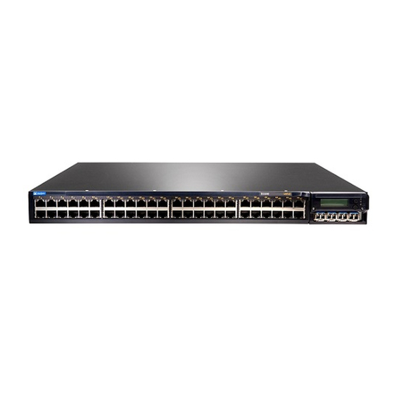
Removing a Transceiver on page 203 Front Panel of an EX3200 Switch The front panel of an EX3200 switch consists of the following components: 10/100/1000Base-T Gigabit Ethernet ports, some or all of which are enabled for Power over Ethernet (PoE) Uplink module ports—SFP, SFP+, or XFP ports (Installing the uplink module is an... -
Page 32: Rear Panel Of An Ex3200 Switch
EX3200 switch with a 320 W power supply. All EX3200 switches have the same rear panel. The 320 W AC power supply and the 190 W DC power supply are flush with the chassis. The 600 W AC power supply and 930 W AC power supply extend out of the chassis by 2.25 in. -
Page 33: Lcd Panel In Ex3200 Switches
Prevention of Electrostatic Discharge Damage on page 269 Connecting Earth Ground to an EX Series Switch on page 155 Installing and Removing EX3200 Switch Hardware Components on page 152 LCD Panel in EX3200 Switches The LCD panel on the front panel of the switch shows two lines of text, each of which can contain a maximum of 16 characters. -
Page 34: Lcd Panel Menus
After the boot process is complete, the LCD panel automatically reverts to the Idle menu. In an EX3200 switch, the first line of the LCD panel displays the hostname. In the idle mode, the second line displays the mode of the network ports’ Status LED and the number of chassis alarms. - Page 35 NOTE: This option is available only for an EX4200 switch that is a member of a Virtual Chassis configuration. It is not available for an EX3200 switch. Press the button to go to the next option in the Status menu.
- Page 36 NOTE: This option is available only for an EX4200 switch that is a member of a Virtual Chassis configuration. It is not available for an EX3200 switch. Press the button to go to the next option in the Maintenance menu.
-
Page 37: Uplink Modules In Ex3200 Switches
SFP uplink module—Provides four ports for 1-gigabit small form-factor pluggable (SFP) transceivers. The model number of the uplink module is EX-UM-4SFP. NOTE: On an EX3200 switch, if you install a transceiver in an SFP uplink module, a corresponding network port from the last four built-in ports is disabled. -
Page 38: Sfp Uplink Module
10-gigabit mode and support only SFP+ transceivers. If you have not changed the module from the default setting and you want to use SFP+ transceivers, you do not need to configure the operating mode. Copyright © 2016, Juniper Networks, Inc. -
Page 39: Figure 6: Sfp+ And Sfp+ Macsec Uplink Module
If the uplink module is operating in the 10-gigabit mode, the LED is lit. If the uplink module is operating in the 1-gigabit mode, the LED is unlit. SFP+ uplink modules and the SFP+ MACsec uplink modules are shipped with dust covers preinstalled in the ports. Copyright © 2016, Juniper Networks, Inc. -
Page 40: Xfp Uplink Module
Troubleshooting Uplink Module Installation or Replacement on EX3200 Switches on page 232 Chassis Status LEDs in EX3200 Switches The front panel of an EX3200 switch has three LEDs on the far right side of the panel, next to the LCD panel (see Figure 8 on page 19). -
Page 41: Figure 8: Chassis Status Leds In An Ex3200 Switch
Figure 8: Chassis Status LEDs in an EX3200 Switch Table 7 on page 19 describes the chassis status LEDs in an EX3200 switch, their colors and states, and the status they indicate. You can view the colors of the three LEDs remotely through the CLI by issuing the operational mode command show chassis lcd. -
Page 42: Management Port Leds In Ex3200 Switches
Understanding Alarm Types and Severity Levels on EX Series Switches on page 219 Management Port LEDs in EX3200 Switches The management port on EX3200 switches has two LEDs that indicate link/activity and port status (see Figure 9 on page 20 ). -
Page 43: Network Port Leds In Ex3200 Switches
Chapter 2: Chassis Components and Descriptions Related Rear Panel of an EX3200 Switch on page 10 for port location. Documentation Connecting a Device to a Network for Out-of-Band Management on page 167 Network Port LEDs in EX3200 Switches Each network port on the switch has two LEDs. The four figures in this topic show the... -
Page 44: Figure 12: Leds On The Uplink Module Ports On The Sfp+ And Sfp+ Macsec Uplink
State and Description Link/Activity Green Blinking—The port and the link are active, and there is link activity. On steadily—The port and the link are active, but there is no link activity. Off—The port is not active. Copyright © 2016, Juniper Networks, Inc. - Page 45 Table 11 on page 24 describes the Status LED. From the Idle menu of the LCD, use the button on the LCD panel to toggle between the ADM, DPX, POE, and SPD indicators. Enter Copyright © 2016, Juniper Networks, Inc.
-
Page 46: Table 11: Status Led On Network Ports
The speed indicators for network ports on the front panel are: One blink per second—10 Mbps Two blinks per second—100 Mbps Three blinks per second—1000 Mbps The speed indicators for network ports on the SFP uplink module are: Green—1000 Mbps Unlit—10/100 Mbps Copyright © 2016, Juniper Networks, Inc. - Page 47 XFP transceivers, therefore, this LED is always green on an XFP uplink module.. Related Front Panel of an EX3200 Switch on page 9 Documentation Uplink Modules in EX3200 Switches on page 15 LCD Panel in EX3200 Switches on page 11...
- Page 48 EX3200 Switch Hardware Guide Copyright © 2016, Juniper Networks, Inc.
-
Page 49: Cooling System And Airflow
Cooling System and Airflow in an EX3200 Switch on page 27 Cooling System and Airflow in an EX3200 Switch The cooling system in an EX3200 switch consists of a field-replaceable unit (FRU) fan tray with one fan (see Figure 14 on page 27). -
Page 50: Figure 15: Airflow Through The Ex3200 Switch Chassis
Rear Panel of an EX3200 Switch on page 10 Prevention of Electrostatic Discharge Damage on page 269 Installing a Fan Tray in an EX3200 Switch on page 187 Removing a Fan Tray from an EX3200 Switch on page 188 Copyright © 2016, Juniper Networks, Inc. -
Page 51: Power Supplies
DC Power Supply LEDs in EX3200 Switches on page 33 Power Supply in EX3200 Switches The power supply in EX3200 switches is a field-replaceable unit (FRU) that you can install on the rear panel. The power supply in EX3200 switches is not redundant. -
Page 52: Dc Power Supplies
“Installing a Power Supply in an EX3200 Switch” on page 191 “Removing a Power Supply from an EX3200 Switch” on page 192 or Installing a Power Supply in an EX4200 Switch or Removing a Power Supply from an EX4200 Switch carefully. -
Page 53: Poe Power Budget And Ac Power Supplies
The PoE power budget for a PoE switch model is determined by the capacity of its power supply. For EX3200 switches, the capacity of the power supply provided with a PoE model is sufficient to supply each PoE-capable port with up to 15.4 W in compliance with the IEEE 802.3af PoE standard. -
Page 54: Ac Power Supply Leds In Ex3200 Switches
Switches upgraded to Junos OS Release 11.1 from a previous release require a separate upgrade of the PoE controller software to enable enhanced PoE support. Table 12: Power Supply Rating and PoE Power Budget for EX3200 Switch Models Number of PoE-enabled Switch Model Number... -
Page 55: Dc Power Supply Leds In Ex3200 Switches
Related Power Supply in EX3200 Switches on page 29 Documentation Connecting AC Power to an EX3200 Switch on page 161 DC Power Supply LEDs in EX3200 Switches Table 14 on page 33 describes the LEDs on the DC power supplies. - Page 56 EX3200 Switch Hardware Guide Related Power Supply in EX3200 Switches on page 29 Documentation Connecting DC Power to an EX3200 Switch on page 163 Copyright © 2016, Juniper Networks, Inc.
-
Page 57: Viewing System Information
NOTE: This topic applies only to the J-Web Application package. When you log in to the J-Web user interface, the dashboard for the Juniper Networks EX Series Ethernet Switches appears. Use the dashboard to view system information. The Update Available window appears if there is a latest update of the J-Web Application package available on the Juniper Networks server. -
Page 58: Graphical Chassis Viewer
Table 16: Status of a Member Switch in a Virtual Chassis If the member switch is It appears as It means the member switch Present Prsnt Has established physical and logical connections with Virtual Chassis member switches. Copyright © 2016, Juniper Networks, Inc. -
Page 59: System Information Panel
NOTE: In a Virtual Chassis setup for an EX6210, EX8208, or EX8216 switch, the Device model field displays details of the master Routing Engine. To view details of a member, select it. Copyright © 2016, Juniper Networks, Inc. - Page 60 EX4550 switches that are not configured as Virtual Chassis, the value displayed in the Inventory details field is always 1 FPC. FPC is a legacy term for a slot in a large Juniper Networks chassis, which simply refers to the standalone switch.
-
Page 61: Health Status Panel
Table 18: Health Status Field Description EX2200, EX2200-C, EX2300, EX2300-C, EX3200, EX3300, EX3400, EX4200, and EX4300 Switches Memory util. Indicates the memory used in the Routing Engine. In a Virtual Chassis configuration, the memory utilization value of the master Routing Engine is displayed. - Page 62 Routing Engine. CPU load Indicates the average CPU usage over 15 minutes. Flash Indicates the usage and capacity of internal flash memory and any external USB flash drive. EX8216 Switches Copyright © 2016, Juniper Networks, Inc.
-
Page 63: Capacity Utilization Panel
Indicates the maximum number of VLANs supported. Alarms Panel The Alarms panel displays information about the last five alarms raised in the system. For example, if there are 5 major alarms, then details of all 5 major alarms are displayed. Copyright © 2016, Juniper Networks, Inc. -
Page 64: File System Usage
Table 22 on page 44—Describes the chassis viewer for EX2300 switches. Table 23 on page 45—Describes the chassis viewer for EX3200, EX3300, and EX4200 switches. Table 24 on page 46—Describes the chassis viewer for EX3400 and EX4300 switches. Table 25 on page 48—Describes the chassis viewer for EX4500 switches. -
Page 65: Table 21: Chassis Viewer For Ex2200-C And Ex2300-C Switches
NOTE: The mini-USB console port is available on EX2300-C switch and is unavailable on EX2200-C switch. We recommend that you use USB flash drives purchased from Juniper Networks for your EX Series switch. Rear View Copyright © 2016, Juniper Networks, Inc. -
Page 66: Table 22: Chassis Viewer For Ex2300 Switches
Indicates the mini-USB port for the switch. This is used to connect the switch to a management console such as a laptop or a PC. (You might do this for initial switch configuration.) NOTE: We recommend that you use USB flash drives purchased from Juniper Networks for your EX Series switch. Rear View USB port Indicates the USB port for the switch. -
Page 67: Table 23: Chassis Viewer For Ex3200, Ex3300, And Ex4200 Switches
USB port Indicates the USB port for the switch. NOTE: We recommend that you use USB flash drives purchased from Juniper Networks for your EX Series switch. Fan tray Mouse over the fan tray icon to display name, status, and description information. -
Page 68: Table 24: Chassis Viewer For Ex3400 And Ex4300 Switches
Gray—VCP is down and nonoperational. USB port Indicates the USB port for the switch. NOTE: We recommend that you use USB flash drives purchased from Juniper Networks for your EX Series switch. Management ( ) port The management port is used to connect the switch to a management device for out-of-band management. - Page 69 USB port Indicates the USB port for the switch. NOTE: We recommend that you use USB flash drives purchased from Juniper Networks for your EX Series switch. Fan tray Mouse over the fan tray icons to display name, status, and description information.
-
Page 70: Table 25: Chassis Viewer For Ex4500 Switches
Use this port for initial switch configuration. USB port Indicates the USB port for the switch. NOTE: We recommend that you use USB flash drives purchased from Juniper Networks for your EX Series switch. Rear View of the EX4500 Switch Fan tray Mouse over the fan tray icon to display status of the fans and airflow direction information. -
Page 71: Table 26: Chassis Viewer For Ex4550 Switches
(uplink or Virtual Chassis). USB port Indicates the USB port for the switch. NOTE: We recommend that you use USB flash drives purchased from Juniper Networks for your EX Series switch. Rear View of the EX4550 Switch Fan tray Mouse over the fan tray icon to display the status of the fans and airflow direction information. -
Page 72: Table 27: Chassis Viewer For Ex6210 Switches
You can view status for the following ports on the SRE module: USB port—Indicates the USB port for the switch. NOTE: We recommend that you use USB flash drives purchased from Juniper Networks for your EX Series switch. Management ( ) port—The management port is used to connect the switch to a management... - Page 73 You can view status for the following ports on the SRE module: USB port—Indicates the USB port for the switch. NOTE: We recommend that you use USB flash drives purchased from Juniper Networks for your EX Series switch. Auxiliary port—This port is unavailable.
-
Page 74: Table 29: Chassis Viewer For Ex8216 Switches
You can view status for the following ports on the RE module: USB port—Indicates the USB port for the switch. NOTE: We recommend that you use USB flash drives purchased from Juniper Networks for your EX Series switch. Auxiliary port—This port is unavailable. - Page 75 Indicates the USB port for the switch. NOTE: We recommend that you use USB flash drives purchased from Juniper Networks for your EX Series switch. PIC1 slot You can install a Virtual Chassis module in the PIC1 slot. Mouse over the Virtual Chassis ports to display the port status details.
- Page 76 J-Web User Interface for EX Series Switches Overview Documentation EX2200 Switches Hardware Overview EX2300 Switches Hardware Overview EX3200 Switches Hardware Overview on page 3 EX3300 Switches Hardware Overview EX4200 Switches Hardware Overview EX4300 Switches Hardware Overview EX4500 Switches Hardware Overview...
-
Page 77: Site Planning, Preparation, And Specifications
PART 2 Site Planning, Preparation, and Specifications Preparation Overview on page 57 Power Specifications and Requirements on page 69 Transceiver and Cable Specifications on page 75 Pinout Specifications on page 119 Copyright © 2016, Juniper Networks, Inc. - Page 78 EX3200 Switch Hardware Guide Copyright © 2016, Juniper Networks, Inc.
-
Page 79: Preparation Overview
Site Electrical Wiring Guidelines on page 63 Rack Requirements on page 64 Cabinet Requirements on page 65 Requirements for Mounting an EX3200 Switch on a Desktop or Wall on page 65 Clearance Requirements for Airflow and Hardware Maintenance for EX3200 Switches on page 66... -
Page 80: Environmental Requirements And Specifications For Ex Series Switches
General Safety Guidelines and Warnings on page 237 Documentation General Site Guidelines on page 62 Installing and Connecting an EX3200 Switch on page 141 Mounting an EX3200 Switch on page 142 Environmental Requirements and Specifications for EX Series Switches The switch must be installed in a rack or cabinet housed in a dry, clean, well-ventilated, and temperature-controlled environment. -
Page 81: Table 32: Ex Series Switch Environmental Tolerances
Complies with Zone 4 degradation up to the relative humidity range temperature range 32° F (0° C) earthquake 10,000 feet 10% through 85% through 113° F (45° C) requirements as per (3048 meters) (noncondensing) GR-63, Issue 4. Copyright © 2016, Juniper Networks, Inc. - Page 82 158° F (70° C) humidity range 5% through 93%, noncondensing NOTE: As defined in NEBS GR-63-CORE, Issue 4, short-term events can be up to 96 hours in duration but not more than 15 days per year. Copyright © 2016, Juniper Networks, Inc.
- Page 83 Complies with Zone 4 degradation up to the relative humidity range temperature range 41° F (5° C) earthquake 10,000 feet 10% through 85% through 104° F (40° C) requirements as per (3048 meters) (noncondensing) GR-63, Issue 4. Copyright © 2016, Juniper Networks, Inc.
-
Page 84: General Site Guidelines
Clearance Requirements for Airflow and Hardware Maintenance for EX2200 Switches Documentation Clearance Requirements for Airflow and Hardware Maintenance for EX2300 Switches Clearance Requirements for Airflow and Hardware Maintenance for EX3200 Switches on page 66 Clearance Requirements for Airflow and Hardware Maintenance for EX3300 Switches... -
Page 85: Site Electrical Wiring Guidelines
Some of the problems caused by strong sources of electromagnetic interference (EMI) are: Destruction of the signal drivers and receivers in the device Electrical hazards as a result of power surges conducted over the lines into the equipment Copyright © 2016, Juniper Networks, Inc. -
Page 86: Rack Requirements
If earthquakes are a possibility in your geographical area, secure the rack to the floor. Secure the rack to the ceiling brackets as well as wall or floor brackets for maximum stability. Related Rack-Mounting and Cabinet-Mounting Warnings on page 248 Documentation Copyright © 2016, Juniper Networks, Inc. -
Page 87: Cabinet Requirements
Rack-Mounting and Cabinet-Mounting Warnings on page 248 Documentation Requirements for Mounting an EX3200 Switch on a Desktop or Wall You can install the switch on or under a desk or other level surface or on a wall. When choosing a location, allow at least 6 in. (15.2 cm) of clearance between the front and back of the chassis and adjacent equipment or walls. -
Page 88: Figure 19: Clearance Requirements For Airflow And Hardware Maintenance For
Insert the screws into wall studs wherever possible to provide added support for the chassis. Use the wall-mount kit from Juniper Networks to mount the switch on a wall. The wall-mount kit is not part of the standard package and must be ordered separately. -
Page 89: Figure 20: Airflow Through The Ex3200 Switch Chassis
Rack Requirements on page 64 Documentation Cabinet Requirements on page 65 General Site Guidelines on page 62 Rack-Mounting and Cabinet-Mounting Warnings on page 248 Cooling System and Airflow in an EX3200 Switch on page 27 Copyright © 2016, Juniper Networks, Inc. - Page 90 EX3200 Switch Hardware Guide Copyright © 2016, Juniper Networks, Inc.
-
Page 91: Switches
Calculating the EX Series Switch Fiber-Optic Cable Power Margin on page 72 Power Specifications for EX3200 Switches This topic describes power specifications for power supplies for EX3200 switches. Table 36 on page 69 provides the AC power supply electrical specifications for EX3200 switches. -
Page 92: Ac Power Cord Specifications For Ex3200 Switches
1 ms minimum NOTE: The DC power supply in EX3200 switches does not support Power over Ethernet (PoE); you can use either an external power injector or an AC power supply to supply power to PoE devices that you connect to the switch. -
Page 93: Figure 21: Ac Plug Types
Table 38 on page Figure 21: AC Plug Types Related Power Supply in EX3200 Switches on page 29 Documentation General Safety Guidelines and Warnings on page 237 General Electrical Safety Guidelines and Warnings on page 267 Copyright © 2016, Juniper Networks, Inc. -
Page 94: Calculating The Ex Series Switch Fiber-Optic Cable Power Budget
) greater than zero indicates that the power budget is sufficient to operate the receiver and that it does not exceed the maximum receiver input power. This means the link will work. A (P ) that is zero or negative indicates insufficient power Copyright © 2016, Juniper Networks, Inc. -
Page 95: Power Specifications And Requirements
For information about the actual amount of signal loss caused by equipment and other factors, see your vendor documentation for that equipment. Calculate the (P ) by subtracting (LL) from (P – LL = P Copyright © 2016, Juniper Networks, Inc. - Page 96 Calculating the EX Series Switch Fiber-Optic Cable Power Budget on page 72 Documentation Understanding EX Series Switches Fiber-Optic Cable Signal Loss, Attenuation, and Dispersion on page 116 Pluggable Transceivers Supported on EX Series Switches on page 109 Copyright © 2016, Juniper Networks, Inc.
-
Page 97: Transceiver And Cable Specifications
Juniper Networks optic or cable that is qualified for the device. The Gigabit Ethernet SFP, SFP+, or XFP transceivers installed in EX3200 switches support digital optical monitoring (DOM): You can view the diagnostic details for these transceivers... -
Page 98: Table 40: Optical Interface Support And Copper Interface Support For Gigabit Ethernet Sfp Transceivers In Ex3200 Switches
Fiber type Copper Core/Cladding size – Modal bandwidth – Distance 100 m (328 ft) DOM support Not available Software required Junos OS for EX Series switches, Release 9.0 or later Support for Virtual Chassis configuration Copyright © 2016, Juniper Networks, Inc. -
Page 99: Transceiver And Cable Specifications
Chapter 8: Transceiver and Cable Specifications Table 40: Optical Interface Support and Copper Interface Support for Gigabit Ethernet SFP Transceivers in EX3200 Switches (continued) Ethernet Standard Specification Value 1000BASE-SX Model number EX-SFP-1GE-SX Rate 1000 Mbps Connector type Fiber count Dual... - Page 100 EX3200 Switch Hardware Guide Table 40: Optical Interface Support and Copper Interface Support for Gigabit Ethernet SFP Transceivers in EX3200 Switches (continued) Ethernet Standard Specification Value 1000BASE-LX Model number EX-SFP-1GE-LX Rate 1000 Mbps Connector type Fiber count Dual Transmitter wavelength...
- Page 101 Chapter 8: Transceiver and Cable Specifications Table 40: Optical Interface Support and Copper Interface Support for Gigabit Ethernet SFP Transceivers in EX3200 Switches (continued) Ethernet Standard Specification Value 1000BASE-BX-U Model number EX-SFP-GE10KT13R14 Rate 1000 Mbps Connector type Fiber count Single...
- Page 102 EX3200 Switch Hardware Guide Table 40: Optical Interface Support and Copper Interface Support for Gigabit Ethernet SFP Transceivers in EX3200 Switches (continued) Ethernet Standard Specification Value 1000BASE-BX-D Model number EX-SFP-GE10KT14R13 Rate 1000 Mbps Connector type Fiber count Single Transmitter wavelength...
- Page 103 Chapter 8: Transceiver and Cable Specifications Table 40: Optical Interface Support and Copper Interface Support for Gigabit Ethernet SFP Transceivers in EX3200 Switches (continued) Ethernet Standard Specification Value 1000BASE-BX-U Model number EX-SFP-GE10KT13R15 Rate 1000 Mbps Connector type Fiber count Single...
- Page 104 EX3200 Switch Hardware Guide Table 40: Optical Interface Support and Copper Interface Support for Gigabit Ethernet SFP Transceivers in EX3200 Switches (continued) Ethernet Standard Specification Value 1000BASE-BX-D Model number EX-SFP-GE10KT15R13 Rate 1000 Mbps Connector type Fiber count Single Transmitter wavelength...
- Page 105 Chapter 8: Transceiver and Cable Specifications Table 40: Optical Interface Support and Copper Interface Support for Gigabit Ethernet SFP Transceivers in EX3200 Switches (continued) Ethernet Standard Specification Value 1000BASE-BX-U Model number EX-SFP-GE40KT13R15 Rate 1000 Mbps Connector type Fiber count Single...
- Page 106 EX3200 Switch Hardware Guide Table 40: Optical Interface Support and Copper Interface Support for Gigabit Ethernet SFP Transceivers in EX3200 Switches (continued) Ethernet Standard Specification Value 1000BASE-BX-D Model number EX-SFP-GE40KT15R13 Rate 1000 Mbps Connector type Fiber count Single Transmitter wavelength...
- Page 107 Chapter 8: Transceiver and Cable Specifications Table 40: Optical Interface Support and Copper Interface Support for Gigabit Ethernet SFP Transceivers in EX3200 Switches (continued) Ethernet Standard Specification Value 1000BASE-LX Model number EX-SFP-1GE-LX40K Rate 1000 Mbps Connector type Fiber count Double...
- Page 108 EX3200 Switch Hardware Guide Table 40: Optical Interface Support and Copper Interface Support for Gigabit Ethernet SFP Transceivers in EX3200 Switches (continued) Ethernet Standard Specification Value 1000BASE-LH (or Model number EX-SFP-1GE-LH 1000BASE-ZX) Rate 1000 Mbps Connector type Fiber count Dual...
- Page 109 Chapter 8: Transceiver and Cable Specifications Table 40: Optical Interface Support and Copper Interface Support for Gigabit Ethernet SFP Transceivers in EX3200 Switches (continued) Ethernet Standard Specification Value 1000BASE-LX Model number EX-SFP-GE80KCW1470 Rate 1000 Mbps Connector type Fiber count Single...
- Page 110 EX3200 Switch Hardware Guide Table 40: Optical Interface Support and Copper Interface Support for Gigabit Ethernet SFP Transceivers in EX3200 Switches (continued) Ethernet Standard Specification Value 1000BASE-LX Model number EX-SFP-GE80KCW1490 Rate 1000 Mbps Connector type Fiber count Single Transmitter wavelength...
- Page 111 Chapter 8: Transceiver and Cable Specifications Table 40: Optical Interface Support and Copper Interface Support for Gigabit Ethernet SFP Transceivers in EX3200 Switches (continued) Ethernet Standard Specification Value 1000BASE-LX Model number EX-SFP-GE80KCW1510 Rate 1000 Mbps Connector type Fiber count Single...
- Page 112 EX3200 Switch Hardware Guide Table 40: Optical Interface Support and Copper Interface Support for Gigabit Ethernet SFP Transceivers in EX3200 Switches (continued) Ethernet Standard Specification Value 1000BASE-LX Model number EX-SFP-GE80KCW1530 Rate 1000 Mbps Connector type Fiber count Single Transmitter wavelength...
- Page 113 Chapter 8: Transceiver and Cable Specifications Table 40: Optical Interface Support and Copper Interface Support for Gigabit Ethernet SFP Transceivers in EX3200 Switches (continued) Ethernet Standard Specification Value 1000BASE-LX Model number EX-SFP-GE80KCW1550 Rate 1000 Mbps Connector type Fiber count Single...
- Page 114 EX3200 Switch Hardware Guide Table 40: Optical Interface Support and Copper Interface Support for Gigabit Ethernet SFP Transceivers in EX3200 Switches (continued) Ethernet Standard Specification Value 1000BASE-LX Model number EX-SFP-GE80KCW1570 Rate 1000 Mbps Connector type Fiber count Single Transmitter wavelength...
- Page 115 Chapter 8: Transceiver and Cable Specifications Table 40: Optical Interface Support and Copper Interface Support for Gigabit Ethernet SFP Transceivers in EX3200 Switches (continued) Ethernet Standard Specification Value 1000BASE-LX Model number EX-SFP-GE80KCW1590 Rate 1000 Mbps Connector type Fiber count Single...
- Page 116 EX3200 Switch Hardware Guide Table 40: Optical Interface Support and Copper Interface Support for Gigabit Ethernet SFP Transceivers in EX3200 Switches (continued) Ethernet Standard Specification Value 1000BASE-LX Model number EX-SFP-GE80KCW1610 Rate 1000 Mbps Connector type Fiber count Single Transmitter wavelength...
-
Page 117: Table 41: Optical Interface Support For Fast Ethernet Sfp Transceivers In Ex3200
Chapter 8: Transceiver and Cable Specifications Table 41: Optical Interface Support for Fast Ethernet SFP Transceivers in EX3200 Switches Ethernet Standard Specification Value 100BASE-FX Model number EX-SFP-1FE-FX Rate 100 Mbps Connector type Fiber count Dual Transmitter wavelength 1310 nm Minimum launch power –20 dBm... - Page 118 EX3200 Switch Hardware Guide Table 41: Optical Interface Support for Fast Ethernet SFP Transceivers in EX3200 Switches (continued) Ethernet Standard Specification Value 100BASE-LX Model number EX-SFP-1FE-LX Rate 100 Mbps Connector type Fiber count Dual Transmitter wavelength 1310 nm Minimum launch power –15 dBm...
- Page 119 Chapter 8: Transceiver and Cable Specifications Table 41: Optical Interface Support for Fast Ethernet SFP Transceivers in EX3200 Switches (continued) Ethernet Standard Specification Value 100BASE-BX-U Model number EX-SFP-FE20KT13R15 Rate 100 Mbps Connector type Fiber count Single Transmitter wavelength 1310 nm...
- Page 120 EX3200 Switch Hardware Guide Table 41: Optical Interface Support for Fast Ethernet SFP Transceivers in EX3200 Switches (continued) Ethernet Standard Specification Value 100BASE-BX-D Model number EX-SFP-FE20KT15R13 Rate 100 Mbps Connector type Fiber count Single Transmitter wavelength 1550 nm Receiver wavelength...
- Page 121 Chapter 8: Transceiver and Cable Specifications Table 41: Optical Interface Support for Fast Ethernet SFP Transceivers in EX3200 Switches (continued) Ethernet Standard Specification Value 100BASE-LX40K Model number EX-SFP-1FE-LX40K Rate 100 Mbps Connector type Fiber count Dual Transmitter wavelength 1310 nm Minimum launch power –5 dBm...
- Page 122 EX3200 Switch Hardware Guide Table 41: Optical Interface Support for Fast Ethernet SFP Transceivers in EX3200 Switches (continued) Ethernet Standard Specification Value 100BASE-LH (or Model number EX-SFP-1FE-LH 100BASE-ZX) Rate 100 Mbps Connector type Fiber count Dual Transmitter wavelength 1310 nm Minimum launch power –5 dBm...
-
Page 123: Table 42: Optical Interface Support For Gigabit Ethernet Sfp+ Transceivers In
Chapter 8: Transceiver and Cable Specifications Table 42: Optical Interface Support for Gigabit Ethernet SFP+ Transceivers in EX3200 Switches Ethernet Standard Specification Value 10GBASE-USR Model number EX-SFP-10GE-USR Rate 10 Gbps Connector type Fiber count Dual Transmitter wavelength 850 nm Minimum launch power –7.3 dBm... - Page 124 EX3200 Switch Hardware Guide Table 42: Optical Interface Support for Gigabit Ethernet SFP+ Transceivers in EX3200 Switches (continued) Ethernet Standard Specification Value 10GBASE-SR Model number EX-SFP-10GE-SR Rate 10 Gbps Connector type Fiber count Dual Transmitter wavelength 850 nm Minimum launch power –7.3 dBm...
- Page 125 Chapter 8: Transceiver and Cable Specifications Table 42: Optical Interface Support for Gigabit Ethernet SFP+ Transceivers in EX3200 Switches (continued) Ethernet Standard Specification Value 10GBASE-LRM Model number EX-SFP-10GE-LRM Rate 10 Gbps Connector type Fiber count Dual Transmitter wavelength 1310 nm Minimum launch power –6.5 dBm...
- Page 126 EX3200 Switch Hardware Guide Table 42: Optical Interface Support for Gigabit Ethernet SFP+ Transceivers in EX3200 Switches (continued) Ethernet Standard Specification Value 10GBASE-LR Model number EX-SFP-10GE-LR Rate 10 Gbps Connector type Fiber count Dual Transmitter wavelength 1310 nm Minimum launch power –8.2 dBm...
- Page 127 Chapter 8: Transceiver and Cable Specifications Table 42: Optical Interface Support for Gigabit Ethernet SFP+ Transceivers in EX3200 Switches (continued) Ethernet Standard Specification Value 10GBASE-ER Model number EX-SFP-10GE-ER Rate 10 Gbps Connector type Fiber count Dual Transmitter wavelength 1550 nm Minimum launch power –4.7 dBm...
-
Page 128: Table 43: Optical Interface Support For Gigabit Ethernet Xfp Transceivers In
EX3200 Switch Hardware Guide Table 43: Optical Interface Support for Gigabit Ethernet XFP Transceivers in EX3200 Switches Ethernet Standard Specification Value 10GBASE-SR Model number EX-XFP-10GE-SR Rate 10 Gbps Connector type Fiber count Dual Transmitter wavelength 850 nm Minimum launch power –7.3 dBm... - Page 129 Chapter 8: Transceiver and Cable Specifications Table 43: Optical Interface Support for Gigabit Ethernet XFP Transceivers in EX3200 Switches (continued) Ethernet Standard Specification Value 10GBASE-LR Model number EX-XFP-10GE-LR Rate 10 Gbps Connector type Fiber count Dual Transmitter wavelength 1310 nm Minimum launch power –8.2 dBm...
- Page 130 EX3200 Switch Hardware Guide Table 43: Optical Interface Support for Gigabit Ethernet XFP Transceivers in EX3200 Switches (continued) Ethernet Standard Specification Value 10GBASE-ER Model number EX-XFP-10GE-ER Rate 10 Gbps Connector type Fiber count Dual Transmitter wavelength 1550 nm Minimum launch power –4.7 dBm...
-
Page 131: Pluggable Transceivers Supported On Ex Series Switches
Chapter 8: Transceiver and Cable Specifications Table 43: Optical Interface Support for Gigabit Ethernet XFP Transceivers in EX3200 Switches (continued) Ethernet Standard Specification Value 10GBASE-ZR Model number EX-XFP-10GE-ZR Rate 10 Gbps Connector type Fiber count Dual Transmitter wavelength 1550 nm... - Page 132 For the list and specifications of transceivers supported on EX2300 switches, see Pluggable Transceivers Supported on EX2300 Switches. For the list and specifications of transceivers supported on EX3200 switches, see “Pluggable Transceivers Supported on EX3200 Switches” on page For the list and specifications of transceivers supported on EX3300 switches, see Pluggable Transceivers Supported on EX3300 Switches.
-
Page 133: Sfp+ Direct Attach Copper Cables For Ex Series Switches
3 ft (1 m), 10 ft (3 m), 16 ft (5 m), and 23 ft (7 m) EX4200-24T, Junos OS Release 10.3 3 ft (1 m), 10 ft (3 m), 16 ft (5 m), and 23 ft (7 m) EX4200-24T-DC, EX4200-24P, EX4200-24PX, EX4200-24F, EX4200-24F-DC, EX4200-48T, EX4200-48T-DC, EX4200-48P, and EX4200-48PX switches Copyright © 2016, Juniper Networks, Inc. - Page 134 16 ft (5 m) EX8200 40-port SFP+ Junos OS Release 10.3 3 ft (1 m), 10 ft (3 m), and 23 ft (7 m) line cards (EX8200-40XS) Junos OS Release 11.1 16 ft (5 m) Copyright © 2016, Juniper Networks, Inc.
-
Page 135: Table 45: Sfp+ Direct Attach Copper Cable Specifications
(JTAC) can help you diagnose the source of the problem. Your JTAC engineer might recommend that you check the third-party optic or cable and potentially replace it with an equivalent Juniper Networks optic or cable that is qualified for the device. - Page 136 Cable type Twinax Wire AWG 24 AWG Minimum cable bend radius 1 in. (2.54 cm) Cable characteristic impedance 100 ohms Crosstalk between pairs 2% maximum Time delay 1.31 nsec/ft Length 16.4 ft (5 m) Copyright © 2016, Juniper Networks, Inc.
-
Page 137: Standards Supported By These Cables
Removing a Transceiver on page 203 Management Cable Specifications Table 46 on page 116 lists the specifications for the cables that connect the console ) and management ( ) ports to management devices. MGMT Copyright © 2016, Juniper Networks, Inc. -
Page 138: Understanding Ex Series Switches Fiber-Optic Cable Signal Loss, Attenuation
For information about the maximum transmission distance and supported wavelength range for the types of single-mode and multimode fiber-optic cables that are used on different EX Series switches see “Pluggable Transceivers Supported on EX Series Switches” on page 109. Copyright © 2016, Juniper Networks, Inc. -
Page 139: Attenuation And Dispersion In Fiber-Optic Cable
(including those from dispersion), and a safety margin for unexpected losses. Related Calculating the EX Series Switch Fiber-Optic Cable Power Budget on page 72 Documentation Calculating the EX Series Switch Fiber-Optic Cable Power Margin on page 72 Copyright © 2016, Juniper Networks, Inc. - Page 140 EX3200 Switch Hardware Guide Copyright © 2016, Juniper Networks, Inc.
-
Page 141: Pinout Specifications
Information on page 121 RJ-45 to DB-9 Serial Port Adapter Pinout Information on page 126 Uplink Modules Connector Pinout Information for EX3200 Switches on page 126 Console Port Connector Pinout Information The console port on a Junier Networks device is an RS-232 serial interface that uses an RJ-45 connector to connect to a console management device. -
Page 142: Usb Port Specifications For An Ex Series Switch
Documentation Configuring the Console Port Type (CLI Procedure) USB Port Specifications for an EX Series Switch The following Juniper Networks USB flash drives have been tested and are officially supported for the USB port on all EX Series switches: RE-USB-1G-S... -
Page 143: Rj-45 Management Port Connector Pinout Information
Booting an EX Series Switch Using a Software Package Stored on a USB Flash Drive RJ-45 Management Port Connector Pinout Information Table 48 on page 121 provides the pinout information for the RJ-45 connector for the management port on Juniper Networks devices. Table 48: RJ-45 Management Port Connector Pinout Information Signal Description... -
Page 144: Table 49: 10/100/1000Base-T Ethernet Network Port Connector Pinout
Table 50: SFP Network Port Connector Pinout Information Signal Description VeeT Module transmitter ground TX_Fault Module transmitter fault TX_Disable Transmitter disabled 2-wire serial interface data line SCL- 2-wire serial interface clock MOD_ABS Module absent Rate select Copyright © 2016, Juniper Networks, Inc. -
Page 145: Table 51: Sfp+ Network Port Connector Pinout Information
2-wire serial interface data line SCL- 2-wire serial interface clock MOD_ABS Module absent Rate select 0, optionally controls SFP+ module receiver RX_LOS Receiver loss of signal indication Rate select 1, optionally controls SFP+ transmitter Copyright © 2016, Juniper Networks, Inc. -
Page 146: Table 52: Qsfp+ Network Port Connector Pinout Information
Module transmitter 3.3 V supply VeeT Module transmitter ground Transmitter noninverted data input Transmitter inverted data input VeeT Module transmitter ground Table 52: QSFP+ Network Port Connector Pinout Information Signal TX2n TX2p TX4n TX4p ModSelL LPMode_Reset VccRx Copyright © 2016, Juniper Networks, Inc. - Page 147 Chapter 9: Pinout Specifications Table 52: QSFP+ Network Port Connector Pinout Information (continued) Signal RX3p RX3n RX1p RX1n RX2n RX2p RX4n RX4p ModPrsL IntL VccTx Vcc1 Reserved TX3p TX3n Copyright © 2016, Juniper Networks, Inc.
-
Page 148: Rj-45 To Db-9 Serial Port Adapter Pinout Information
Connecting a Device to a Management Console by Using an RJ-45 Connector on page 168 Documentation Uplink Modules Connector Pinout Information for EX3200 Switches EX3200 switches have a field-replaceable unit (FRU) uplink module on the front panel. Table 54 on page 127 provides the uplink modules connector pinout information. -
Page 149: Table 54: Uplink Modules Connector Pinout Information
Chapter 9: Pinout Specifications NOTE: You can use these ports to connect an access switch to a distribution switch. Table 54: Uplink Modules Connector Pinout Information Pin Number Pin Name Uplink_I2C_SCK Uplink_PD POWER (12V) Copyright © 2016, Juniper Networks, Inc. - Page 150 EX3200 Switch Hardware Guide Table 54: Uplink Modules Connector Pinout Information (continued) Pin Number Pin Name XAUI0_RX0N XAUI0_RX2N Uplink_P25_LED2 XAUI1_RX0N Uplink_P27_LED2 XAUI1_RX2N SRX28N Uplink_XAUI_XMDIO SRX26N SGMIIRXN Uplink_I2C_Rst Uplink_Intr Uplink_Pwr_En Uplink_P26_LED0 POWER (12V) POWER (12V) XAUI0_RX0P XAUI0_RX2P Copyright © 2016, Juniper Networks, Inc.
- Page 151 Chapter 9: Pinout Specifications Table 54: Uplink Modules Connector Pinout Information (continued) Pin Number Pin Name XAUI1_RX0P XAUI1_RX2P SRX28P SRX26P SGMIIRXP CPU_UPLINK_MDC Uplink_I2C_SDA CPU_UPLINK_MDIO Uplink_P26_LED1 UPLNK_PWR_OK POWER (12V) XAUI0_TX1N XAUI0_TX3N XAUI1_TX1N XAUI1_TX3N Copyright © 2016, Juniper Networks, Inc.
- Page 152 EX3200 Switch Hardware Guide Table 54: Uplink Modules Connector Pinout Information (continued) Pin Number Pin Name STX27N STX25N Uplink_Rst Uplink_Status_LED0 POWER (12V) XAUI0_TX0N XAUI0_TX1P XAUI0_TX2N XAUI0_TX3P XAUI1_TX0N XAUI1_TX1P XAUI1_TX2N XAUI1_TX3P STX28N STX27P STX26N STX25P Copyright © 2016, Juniper Networks, Inc.
- Page 153 Chapter 9: Pinout Specifications Table 54: Uplink Modules Connector Pinout Information (continued) Pin Number Pin Name SGMIITXN Uplink_Hotswap_LED Uplink_Spare_Intr Uplink_Status_LED1 Uplink_P27_LED0 POWER (12V) POWER (12V) XAUI0_TX0P XAUI0_TX2P XAUI1_TX0P XAUI_TX2P STX28P STX26P SGMIITXP Uplink_Expander_Intr Copyright © 2016, Juniper Networks, Inc.
- Page 154 EX3200 Switch Hardware Guide Table 54: Uplink Modules Connector Pinout Information (continued) Pin Number Pin Name Uplink_P27_LED1 POWER (12V) XAUI0_RX1N XAUI0_RX3N XAUI1_RX1N XAUI1_RX3N SRX27N SRX25N Uplink_P25_LED0 POWER (12V) Uplink_PD_Loopback Copyright © 2016, Juniper Networks, Inc.
- Page 155 Chapter 9: Pinout Specifications Table 54: Uplink Modules Connector Pinout Information (continued) Pin Number Pin Name XAUI0_RX1P XAUI0_RX3P Uplink_P26_ LED2 XAUI1_RX1P Uplink_P28_ LED2 XAUI1_RX3P SRX27P Uplink_XAUI_MDC SRX25P Serial_RX Uplink_P25_LED1 Uplink_P28_LED0 POWER (12V) POWER (12V) Copyright © 2016, Juniper Networks, Inc.
- Page 156 Uplink Modules in EX3200 Switches on page 15 Documentation Front Panel of an EX3200 Switch on page 9 Installing an Uplink Module in an EX3200 Switch on page 195 Removing an Uplink Module from an EX3200 Switch on page 197 Copyright © 2016, Juniper Networks, Inc.
-
Page 157: Part 3 Initial Installation And Configuration
Unpacking the Switch on page 137 Installing the Switch on page 141 Connecting the Switch to Power on page 155 Connecting the Switch to the Network on page 167 Performing Initial Configuration on page 171 Copyright © 2016, Juniper Networks, Inc. - Page 158 EX3200 Switch Hardware Guide Copyright © 2016, Juniper Networks, Inc.
-
Page 159: Unpacking The Switch
Registering Products—Mandatory for Validating SLAs on page 139 Unpacking an EX3200 Switch The EX3200 switch chassis is a rigid sheet-metal structure that houses the hardware components. EX3200 switches are shipped in a cardboard carton, secured with foam packing material. The carton also contains an accessory box. -
Page 160: Parts Inventory (Packing List) For An Ex3200 Switch
Connecting and Configuring an EX Series Switch (J-Web Procedure) on page 178 Parts Inventory (Packing List) for an EX3200 Switch The EX3200 switches are shipped in a cardboard carton, secured with foam packing material. The carton contains an accessory box. -
Page 161: Registering Products-Mandatory For Validating Slas
EX3200 Switches Hardware Overview on page 3 Registering Products—Mandatory for Validating SLAs Register all new Juniper Networks hardware products and changes to an existing installed product on the Juniper Networks website. Registration is mandatory for activating your hardware service-level agreements (SLAs). - Page 162 Register your products at: https://tools.juniper.net/svcreg/SRegSerialNum.jsp Update your installation base at: If you have a Juniper J-Care service contract, register any addition, change, or upgrade of hardware components at . Failure to do so https://www.juniper.net/customers/support/tools/updateinstallbase/ can result in significant delays if you need replacement parts.
-
Page 163: Installing The Switch
Mounting an EX3200 Switch on Four Posts in a Rack or Cabinet on page 146 Mounting an EX3200 Switch in a Recessed Position in a Rack or Cabinet on page 150 Mounting an EX3200 Switch on a Wall on page 150... -
Page 164: Mounting An Ex3200 Switch
Mounting an EX3200 Switch on Two Posts in a Rack or Cabinet on page 144 Documentation Mounting an EX3200 Switch on Four Posts in a Rack or Cabinet on page 146 Mounting an EX3200 Switch in a Recessed Position in a Rack or Cabinet on page 150 Copyright © 2016, Juniper Networks, Inc. -
Page 165: Mounting An Ex3200 Switch On A Desk Or Other Level Surface
Mounting an EX3200 Switch on a Desk or Other Level Surface You can mount an EX3200 switch on a desk or other level surface by using the 4 rubber feet that are shipped with the switch. The rubber feet stabilize the chassis. -
Page 166: Mounting An Ex3200 Switch On Two Posts In A Rack Or Cabinet
Mounting an EX3200 Switch on Two Posts in a Rack or Cabinet You can mount an EX3200 switch on two posts of a 19-in. rack (either a two-post or a four-post rack) or a 19-in. cabinet by using the mounting brackets provided with the switch. -
Page 167: Figure 25: Attaching The Mounting Bracket To The Side Panel Of The Switch
Align the bottom hole in both the mounting brackets with a hole in each rack rail, making sure the chassis is level. See Figure 26 on page 146. Copyright © 2016, Juniper Networks, Inc. -
Page 168: Mounting An Ex3200 Switch On Four Posts In A Rack Or Cabinet
Mounting an EX3200 Switch on Four Posts in a Rack or Cabinet You can mount an EX3200 switch on four posts of a 19-in. rack or cabinet by using the separately orderable four-post rack-mount kit. (The remainder of this topic uses “rack”... - Page 169 Before mounting the switch on four posts in a rack: Verify that the site meets the requirements described in “Site Preparation Checklist for EX3200 Switches” on page Place the rack in its permanent location, allowing adequate clearance for airflow and maintenance, and secure it to the building structure.
-
Page 170: Figure 27: Attaching The Front-Mounting Bracket To The Side Mounting-Rail
Align the bottom hole in both the front-mounting brackets with a hole in each rack rail, making sure the chassis is level. See Figure 29 on page 149. Copyright © 2016, Juniper Networks, Inc. -
Page 171: Figure 29: Mounting The Switch To The Front Posts In A Rack
Related Connecting Earth Ground to an EX Series Switch on page 155 Documentation Connecting AC Power to an EX3200 Switch on page 161 Copyright © 2016, Juniper Networks, Inc. -
Page 172: Mounting An Ex3200 Switch In A Recessed Position In A Rack Or Cabinet
Mounting an EX3200 Switch in a Recessed Position in a Rack or Cabinet You can mount an EX3200 switch in a rack or cabinet such that the switch is recessed inside the rack from the rack front by 2 inches. You can use the 2-in.-recess front brackets provided in the separately orderable four-post rack-mount kit to mount the switch in a recessed position. -
Page 173: Figure 31: Attaching Wall-Mount Brackets To The Switch Chassis
(wall board with a gypsum plaster core) or in wall board not backed by wall studs WARNING: When mounted in a vertical position, an EX3200 switch must be oriented with the front panel of the chassis pointing down in order to ensure proper airflow and meet safety requirements in the event of a fire. -
Page 174: Installing And Removing Ex3200 Switch Hardware Components
Connecting and Configuring an EX Series Switch (J-Web Procedure) on page 178 Wall-Mounting Warning for EX3200 Switches on page 252 Installing and Removing EX3200 Switch Hardware Components The EX3200 switch chassis is a rigid sheet-metal structure that houses the hardware components. The field-replaceable units (FRUs) in EX3200 switches are: Power supply... - Page 175 “Removing an Uplink Module from an EX3200 Switch” on page 197. To install an SFP, SFP+, or XFP transceiver in an EX3200 switch, follow instructions in “Installing a Transceiver” on page 201. To remove an SFP, SFP+, or XFP transceiver from an EX3200 switch, follow instructions in “Removing a Transceiver”...
- Page 176 EX3200 Switch Hardware Guide Copyright © 2016, Juniper Networks, Inc.
-
Page 177: Connecting The Switch To Power
Connecting the Switch to Power Connecting Earth Ground to an EX Series Switch on page 155 Connecting AC Power to an EX3200 Switch on page 161 Connecting DC Power to an EX3200 Switch on page 163 Connecting Earth Ground to an EX Series Switch... -
Page 178: Table 56: Parts And Tools Required For Connecting An Ex Series Switch To Earth Ground
Phillips (+) of the minimum 90°C LCC10-14BWL or screws with #10 number 2 chassis wire, or as equivalent— split-lock washer— permitted by the not provided not provided local code Two #10 flat washers—not provided Copyright © 2016, Juniper Networks, Inc. -
Page 179: Special Instructions To Follow Before Connecting Earth Ground To A
Two ¼-20 x 0.5 in. Phillips (+) the chassis mm²), minimum LCD2-14A-Q or screws with #¼” number 2 60°C wire, or as equivalent split-washer permitted by the —provided —provided local code Two #¼” flat washers— provided Copyright © 2016, Juniper Networks, Inc. -
Page 180: Switch
Special Instructions EX3200 NOTE: Some early variants of EX3200 switches for which the Juniper Networks model number on the label next to the protective earthing terminal is from 750-021xxx through 750-030xxx require 10-24x.25 in. screws. Copyright © 2016, Juniper Networks, Inc. -
Page 181: Figure 33: Connecting The Grounding Lug To A Switch Mounted On Four Posts Of
Special Instructions EX4200 NOTE: Some early variants of EX4200 switches for which the Juniper Networks model number on the label next to the protective earthing terminal is from 750-021xxx through 750-030xxx require 10-24x.25 in. screws. NOTE: The protective earthing terminal on an EX4200 switch mounted on four posts of a rack is accessible through the slot on the left rear bracket only if the rack is 27.5 in. -
Page 182: Connecting Earth Ground To An Ex Series Switch
Connecting DC Power to an EX2200 Switch Connecting AC Power to an EX2300 Switch Connecting AC Power to an EX3200 Switch on page 161 Connecting DC Power to an EX3200 Switch on page 163 Connecting AC Power to an EX3300 Switch... -
Page 183: Connecting Ac Power To An Ex3200 Switch
Grounded Equipment Warning on page 252 Connecting AC Power to an EX3200 Switch The power supply in an EX3200 switch is a field-replaceable unit (FRU). Before you begin connecting AC power to an EX3200 switch: Ensure that you have connected the switch chassis to earth ground. - Page 184 EX3200 Switch Hardware Guide Install the power supply in the chassis. For instructions on installing a power supply in an EX3200 switch, see “Installing a Power Supply in an EX3200 Switch” on page 191. NOTE: The power supply must be connected to a dedicated power source outlet.
-
Page 185: Connecting Dc Power To An Ex3200 Switch
AC Power Supply LEDs in EX3200 Switches on page 32 Connecting DC Power to an EX3200 Switch The power supply in an EX3200 switch is a field-replaceable unit (FRU). Figure 37: DC Power Supply in an EX3200 Switch Copyright © 2016, Juniper Networks, Inc. - Page 186 To meet safety and electromagnetic interference (EMI) requirements and to ensure proper operation, you must connect EX3200 switches to earth ground before you connect them to power. For installations that require a separate grounding conductor to the chassis, use the protective earthing terminal on the switch chassis to connect to the earth ground.
-
Page 187: Figure 38: Removing The Terminal Block Cover From A Dc Power Supply
Do not overtighten—apply between 8 lb-in. (0.9 Nm) and 9 lb-in. (1.02 Nm) of torque to the screws. If you have a second installed power supply, connect it in the same way you did the first. To connect one power supply to two power sources: Copyright © 2016, Juniper Networks, Inc. -
Page 188: Figure 39: Securing Ring Lugs To The Terminals On The Dc Power Supply
Connecting and Configuring an EX Series Switch (CLI Procedure) on page 175 Documentation Connecting and Configuring an EX Series Switch (J-Web Procedure) on page 178 Power Supply in EX3200 Switches on page 29 DC Power Supply LEDs in EX3200 Switches on page 33 Copyright © 2016, Juniper Networks, Inc. -
Page 189: Connecting The Switch To The Network
Figure 41 on page 168): Connect one end of the Ethernet cable to the management port (labeled MGMT ) on the device. ETHERNET Connect the other end of the Ethernet cable to the management device. Copyright © 2016, Juniper Networks, Inc. -
Page 190: Connector
PC directly to the device, use a combination of the RJ-45 to DB-9 female adapter supplied with the device and a USB to DB-9 male adapter. You must provide the USB to DB-9 male adapter. Copyright © 2016, Juniper Networks, Inc. -
Page 191: Connecting A Fiber-Optic Cable
If the fiber-optic cable connector is covered with a rubber safety cap, remove the cap. Save the cap. Remove the rubber safety cap from the optical transceiver. Save the cap. Insert the cable connector into the optical transceiver (see Figure 45 on page 170). Copyright © 2016, Juniper Networks, Inc. -
Page 192: Figure 45: Connecting A Fiber-Optic Cable To An Optical Transceiver Installed In
Related Disconnecting a Fiber-Optic Cable from a Device on page 208 Documentation Installing a Transceiver on page 201 Maintaining Fiber-Optic Cables on page 209 Copyright © 2016, Juniper Networks, Inc. -
Page 193: Performing Initial Configuration
See Reverting to the Default Factory Configuration for the EX Series Switch. The following factory default configuration file is for an EX3200 switch with 24 ports (for models that have more ports, this default configuration file has more interfaces):... - Page 194 { unit 0 { family ethernet-switching; ge-0/0/5 { unit 0 { family ethernet-switching; ge-0/0/6 { unit 0 { family ethernet-switching; ge-0/0/7 { unit 0 { family ethernet-switching; ge-0/0/8 { unit 0 { family ethernet-switching; Copyright © 2016, Juniper Networks, Inc.
- Page 195 0 { family ethernet-switching; ge-0/0/16 { unit 0 { family ethernet-switching; ge-0/0/17 { unit 0 { family ethernet-switching; ge-0/0/18 { unit 0 { family ethernet-switching; ge-0/0/19 { unit 0 { family ethernet-switching; ge-0/0/20 { Copyright © 2016, Juniper Networks, Inc.
- Page 196 0 { family ethernet-switching; ge-0/1/1 { unit 0 { family ethernet-switching; ge-0/1/2 { unit 0 { family ethernet-switching; ge-0/1/3 { unit 0 { family ethernet-switching; protocols { igmp-snooping{ vlan all; lldp { interface all; Copyright © 2016, Juniper Networks, Inc.
-
Page 197: Connecting And Configuring An Ex Series Switch (Cli Procedure)
, revert to the factory-default configuration. See Reverting to the Default Factory Configuration for the EX Series Switch. Using the CLI, set the following parameter values in the console server or PC: Baud rate—9600 Flow control—None Data—8 Parity—None Copyright © 2016, Juniper Networks, Inc. - Page 198 For the location of the console port on different EX Series switches: See EX2200 Switches Hardware Overview. See EX2300 Switches Hardware Overview. “Rear Panel of an EX3200 Switch” on page See Rear Panel of an EX3300 Switch. See Rear Panel of an EX3400 Switch.
- Page 199 IP address. If the connection cannot be made, the J-Web interface displays instructions for starting a J-Web session. Related Connecting and Configuring an EX Series Switch (J-Web Procedure) on page 178 Documentation Installing and Connecting an EX2200 Switch Copyright © 2016, Juniper Networks, Inc.
-
Page 200: Connecting And Configuring An Ex Series Switch (J-Web Procedure)
EX3200 Switch Hardware Guide Installing and Connecting an EX2300 Switch Installing and Connecting an EX3200 Switch on page 141 Installing and Connecting an EX3300 Switch Installing and Connecting an EX3400 Switch Installing and Connecting an EX4200 Switch Installing and Connecting an EX4300 Switch... - Page 201 RJ-45 network ports on the front panel blink when the switch is in the initial setup mode. EX3200, EX3300, EX4200, EX4300, EX4500, EX4550, EX6200, and EX8200 switch—The LCD panel displays a countdown timer when the switch is in initial setup mode.
-
Page 202: Figure 46: Lcd Panel In An Ex3200, Ex4200, Ex4500, Ex4550, Or Ex8200
LCD panel (see Menu Enter Figure 46 on page 180 Figure 47 on page 180). Figure 46: LCD Panel in an EX3200, EX4200, EX4500, EX4550, or EX8200 Switch Figure 47: LCD Panel in an EX4300 Switch 1— LCD panel 3—... - Page 203 Chapter 14: Performing Initial Configuration EX2200, EX2200-C, EX2300, EX2300-C, EX3200, EX3400, or EX4200 switch—Connect the cable to port 0 (ge-0/0/0) on the front panel of the switch. EX3300, EX4500, or EX4550 switch—Connect the cable to the port labeled MGMT on the front panel (LCD panel side) of the switch.
- Page 204 Documentation Installing and Connecting an EX2200 Switch Installing and Connecting an EX2300 Switch Installing and Connecting an EX3200 Switch on page 141 Installing and Connecting an EX3300 Switch Installing and Connecting an EX4200 Switch Installing and Connecting an EX4300 Switch...
-
Page 205: Configuring The Lcd Panel On Ex Series Switches (Cli Procedure)
[edit] user@switch# delete chassis lcd-menu menu-item menu-name disable To disable a menu option: [edit] user@switch# set chassis lcd-menu menu-item menu-option disable To enable a menu option: [edit] user@switch# delete chassis lcd-menu menu-item menu-option disable Copyright © 2016, Juniper Networks, Inc. -
Page 206: Configuring A Custom Display Message
5 minutes or permanently. To display a custom message temporarily: On an EX3200 switch, a standalone EX3300 switch, a standalone EX4200 switch, a standalone EX4300 switch, a standalone EX4500 switch, a standalone EX4550 switch, an EX6200 switch, an EX8200 switch, or an XRE200 External Routing Engine: user@switch>... -
Page 207: Part 4 Installing, Maintaining, And Replacing Components
Replacing Power Supply on page 191 Replacing Uplink Module on page 195 Replacing Transceiver on page 201 Maintaining and Replacing Fiber-Optic Cable on page 207 Contacting Customer Support and Returning the Chassis or Components on page 211 Copyright © 2016, Juniper Networks, Inc. - Page 208 EX3200 Switch Hardware Guide Copyright © 2016, Juniper Networks, Inc.
-
Page 209: Replacing Cooling System Component
Removing a Fan Tray from an EX3200 Switch on page 188 Installing a Fan Tray in an EX3200 Switch EX3200 switches have a single fan tray on the rear panel. The fan tray is a hot-removable and hot-insertable field-replaceable unit (FRU): You can remove and replace it without powering off the switch or disrupting switch functions. -
Page 210: Removing A Fan Tray From An Ex3200 Switch
Rear Panel of an EX3200 Switch on page 10 Removing a Fan Tray from an EX3200 Switch EX3200 switches have a single fan tray on the rear panel. The fan tray is a hot-removable and hot-insertable field-replaceable unit (FRU): You can remove and replace it without powering off the switch or disrupting switch functions. - Page 211 Chapter 15: Replacing Cooling System Component Related Installing a Fan Tray in an EX3200 Switch on page 187 Documentation Installing and Removing EX3200 Switch Hardware Components on page 152 Cooling System and Airflow in an EX3200 Switch on page 27...
- Page 212 EX3200 Switch Hardware Guide Copyright © 2016, Juniper Networks, Inc.
-
Page 213: Replacing Power Supply
CHAPTER 16 Replacing Power Supply Installing a Power Supply in an EX3200 Switch on page 191 Removing a Power Supply from an EX3200 Switch on page 192 Installing a Power Supply in an EX3200 Switch The power supply in EX3200 switches is a field-replaceable unit (FRU). -
Page 214: Removing A Power Supply From An Ex3200 Switch
Related Removing a Power Supply from an EX3200 Switch on page 192 Documentation Installing and Removing EX3200 Switch Hardware Components on page 152 Power Supply in EX3200 Switches on page 29... - Page 215 Take care not to touch power supply components, pins, leads, or solder connections. Place the power supply in the antistatic bag or on the antistatic mat placed on a flat, stable surface. Copyright © 2016, Juniper Networks, Inc.
-
Page 216: Figure 51: Removing A Power Supply From The Switch
EX3200 Switch Hardware Guide Figure 51: Removing a Power Supply from the Switch Related Installing a Power Supply in an EX3200 Switch on page 191 Documentation Installing and Removing EX3200 Switch Hardware Components on page 152 Power Supply in EX3200 Switches on page 29... -
Page 217: Replacing Uplink Module
Removing an Uplink Module from an EX3200 Switch on page 197 Installing an Uplink Module in an EX3200 Switch If your EX3200 switch includes an optional uplink module, you install it in the switch's front panel. The different types of uplink modules are described in “Uplink Modules in... - Page 218 EX3200 Switch Hardware Guide Before you begin installing an uplink module in an EX3200 switch: Ensure that you have taken the necessary precautions to prevent ESD damage (see “Prevention of Electrostatic Discharge Damage” on page 269). Ensure that you have the following parts and tools available: Electrostatic discharge (ESD) grounding strap (If a grounding strap is not available, follow the alternative grounding method described in Step 1 of the following procedure.)
-
Page 219: Removing An Uplink Module From An Ex3200 Switch
Front Panel of an EX3200 Switch on page 9 Removing an Uplink Module from an EX3200 Switch If your EX3200 switch includes an optional uplink module, it is installed in the switch's front panel. The different types of uplink modules are described in “Uplink Modules in... -
Page 220: Figure 53: Sliding The Screwdriver To The Narrow Part Of The Keyhole
Slide the screwdriver out of the keyhole. Place the uplink module in an antistatic bag or on an antistatic mat placed on a flat, stable surface. Figure 53: Sliding the Screwdriver to the Narrow Part of the Keyhole Copyright © 2016, Juniper Networks, Inc. -
Page 221: Figure 54: Removing An Uplink Module From An Ex3200 Switch
Chapter 17: Replacing Uplink Module Figure 54: Removing an Uplink Module from an EX3200 Switch Related Installing an Uplink Module in an EX3200 Switch on page 195 Documentation Installing and Removing EX3200 Switch Hardware Components on page 152 Field-Replaceable Units in EX3200 Switches on page 8 Front Panel of an EX3200 Switch on page 9 Copyright ©... - Page 222 EX3200 Switch Hardware Guide Copyright © 2016, Juniper Networks, Inc.
-
Page 223: Replacing Transceiver
NOTE: On an EX3200 switch, if you install a transceiver in a 1-Gigabit Ethernet uplink module port, a corresponding network port from the last four built-in ports is disabled. For example, if you install a transceiver in the uplink module... - Page 224 Remove the rubber safety cap when you are ready to connect the cable to the transceiver. WARNING: Do not look directly into a fiber-optic transceiver or into the ends of fiber-optic cables. Fiber-optic transceivers and fiber-optic cables connected to transceivers emit laser light that can damage your eyes. Copyright © 2016, Juniper Networks, Inc.
-
Page 225: Removing A Transceiver
Documentation Connecting a Fiber-Optic Cable on page 169 Removing a Transceiver The transceivers for Juniper Networks devices are hot-removable and hot-insertable field-replaceable units (FRUs): You can remove and replace them without powering off the device or disrupting device functions. NOTE:... - Page 226 Remove the cable connected to the transceiver (see “Disconnecting a Fiber-Optic Cable from a Device” on page 208). Cover the transceiver and the end of each fiber-optic cable connector with a rubber safety cap immediately after disconnecting the fiber-optic cables. Copyright © 2016, Juniper Networks, Inc.
-
Page 227: Figure 56: Removing An Sfp, Sfp+, Xfp, Or A Qsfp+ Transceiver
Place the transceiver in the antistatic bag or on the antistatic mat placed on a flat, stable surface. Place the dust cover over the empty port. Related Installing a Transceiver on page 201 Documentation Copyright © 2016, Juniper Networks, Inc. - Page 228 EX3200 Switch Hardware Guide Copyright © 2016, Juniper Networks, Inc.
-
Page 229: Maintaining And Replacing Fiber-Optic Cable
If the fiber-optic cable connector is covered with a rubber safety cap, remove the cap. Save the cap. Remove the rubber safety cap from the optical transceiver. Save the cap. Insert the cable connector into the optical transceiver (see Figure 45 on page 170). Copyright © 2016, Juniper Networks, Inc. -
Page 230: Disconnecting A Fiber-Optic Cable From A Device
Maintaining Fiber-Optic Cables on page 209 Disconnecting a Fiber-Optic Cable from a Device Juniper Networks devices have field-replaceable unit (FRU) optical transceivers to which you can connect fiber-optic cables. Before you begin disconnecting a fiber-optic cable from an optical transceiver, ensure that you have taken the necessary precautions for safe handling of lasers. -
Page 231: Maintaining Fiber-Optic Cables
Removing a Transceiver on page 203 Maintaining Fiber-Optic Cables on page 209 Maintaining Fiber-Optic Cables Fiber-optic cables connect to optical transceivers that are installed in Juniper Networks devices. To maintain fiber-optic cables: When you unplug a fiber-optic cable from a transceiver, place rubber safety caps over the transceiver and on the end of the cable. - Page 232 Opptex Cletop-S Fiber Cleaner. Follow the directions in the cleaning kit you use. Related Connecting a Fiber-Optic Cable on page 169 Documentation Laser and LED Safety Guidelines and Warnings on page 256 Copyright © 2016, Juniper Networks, Inc.
-
Page 233: Components
Packing an EX3200 Switch or Component for Shipping on page 214 Returning an EX3200 Switch or Component for Repair or Replacement If you need to return a switch or hardware component to Juniper Networks for repair or replacement, follow this procedure: Determine the serial number of the component. -
Page 234: Listing The Switch And Components Details With The Cli
Listing the Switch and Components Details with the CLI on page 212 Locating the Chassis Serial Number ID Label on an EX3200 Switch on page 212 Locating the Serial Number ID Labels on FRUs in an EX3200 Switch on page 212 Listing the Switch and Components Details with the CLI... -
Page 235: Contacting Customer Support To Obtain Return Material Authorization
Returning an EX3200 Switch or Component for Repair or Replacement on page 211 Contacting Customer Support to Obtain Return Material Authorization If you are returning a device or hardware component to Juniper Networks for repair or replacement, obtain a Return Material Authorization (RMA) number from Juniper Networks Technical Assistance Center (JTAC). -
Page 236: Packing An Ex3200 Switch Or Component For Shipping
Documentation Packing an EX3200 Switch or Component for Shipping If you are returning an EX3200 switch or component to Juniper Networks for repair or replacement, pack the item as described in this topic. Before you begin packing the switch or component: Ensure that you have retrieved the original shipping carton and packing materials. -
Page 237: Packing An Ex3200 Switch For Shipping
Chapter 20: Contacting Customer Support and Returning the Chassis or Components Packing an EX3200 Switch for Shipping To pack a switch for shipping: On the console or other management device connected to the switch, enter the CLI operational mode and issue the following command to shut down the switch software: user@switch>... - Page 238 Write the RMA number on the exterior of the box to ensure proper tracking. Related Returning an EX3200 Switch or Component for Repair or Replacement on page 211 Documentation Removing a Fan Tray from an EX3200 Switch on page 188...
-
Page 239: Troubleshooting
PART 5 Troubleshooting Alarms and Syslog Messages on page 219 Troubleshooting Switch Components on page 231 Copyright © 2016, Juniper Networks, Inc. - Page 240 EX3200 Switch Hardware Guide Copyright © 2016, Juniper Networks, Inc.
-
Page 241: Alarms And Syslog Messages
This topic applies only to the J-Web Application package. Alarms alert you to conditions that might prevent normal operation of the switch. Before monitoring alarms on a Juniper Networks EX Series Ethernet switch, become familiar with the terms defined in Table 58 on page 219. -
Page 242: Chassis Component Alarm Conditions On Ex3200 Switches
This topic describes the chassis component alarm conditions on EX3200 switches. Table 59 on page 221 lists the alarms that the chassis components can generate on EX3200 switches, their severity levels, and the actions you can take to respond to them. Copyright © 2016, Juniper Networks, Inc. -
Page 243: Table 59: Chassis Component Alarm Conditions On Ex3200 Switches
Chapter 21: Alarms and Syslog Messages Table 59: Chassis Component Alarm Conditions on EX3200 Switches Chassis Alarm Component Alarm Condition Severity Remedy Power A power supply has Minor Install a power supply. supplies been removed from (yellow) the chassis. An unknown power... - Page 244 EX3200 Switch Hardware Guide Table 59: Chassis Component Alarm Conditions on EX3200 Switches (continued) Chassis Alarm Component Alarm Condition Severity Remedy Temperature The temperature Major Check the fan. inside the chassis (red) Open a support case using the Case has exceeded Manager link at 203°...
- Page 245 Chapter 21: Alarms and Syslog Messages Table 59: Chassis Component Alarm Conditions on EX3200 Switches (continued) Chassis Alarm Component Alarm Condition Severity Remedy Media Device booted from Minor Open a support case using the Case backup root. (yellow) Manager link at http://www.juniper.net/support/...
- Page 246 EX3200 Switch Hardware Guide Table 59: Chassis Component Alarm Conditions on EX3200 Switches (continued) Chassis Alarm Component Alarm Condition Severity Remedy Redundant RPS is Major Check the RPS connection. disconnected. (red) power system (RPS) RPS fan has failed. Major Open a support case using the Case...
-
Page 247: Checking Active Alarms With The J-Web Interface
Related Field-Replaceable Units in EX3200 Switches on page 8 Documentation Chassis Status LEDs in EX3200 Switches on page 18 Understanding Alarm Types and Severity Levels on EX Series Switches on page 219 Checking Active Alarms with the J-Web Interface Purpose NOTE: This topic applies only to the J-Web Application package. -
Page 248: Monitoring System Log Messages
Apply a filter or a combination of filters to view messages. You can use filters to display relevant events. Table 61 on page 227 describes the different filters, their functions, and the associated actions. To view events in the CLI, enter the following command: show log Copyright © 2016, Juniper Networks, Inc. -
Page 249: Table 61: Filtering System Log Messages
To apply the filter and display messages, click matching messages. Search Reset Resets all the fields in the Events Filter box. To reset the field values that are listed in the Events Filter box, click Reset Copyright © 2016, Juniper Networks, Inc. -
Page 250: Table 62: Viewing System Log Messages
Routing Engine than for messages generated on another Routing Engine (on a system with two Routing Engines installed and operational). Messages from the other Routing Engine also include the identifiers that identify the Routing Engine. Copyright © 2016, Juniper Networks, Inc. - Page 251 Displays the time at which the message was logged. Related Checking Active Alarms with the J-Web Interface on page 225 Documentation Understanding Alarm Types and Severity Levels on EX Series Switches on page 219 Copyright © 2016, Juniper Networks, Inc.
- Page 252 EX3200 Switch Hardware Guide Copyright © 2016, Juniper Networks, Inc.
-
Page 253: Troubleshooting Switch Components
The interface on the port in which an SFP or SFP+ transceiver is installed in an SFP+ uplink module is down on page 232 The interface on one of the last four built-in network ports in an EX3200 switch (for example, interface ge-0/0/23) is down... -
Page 254: The Interface On The Port In Which An Sfp Or Sfp+ Transceiver Is Installed In An Sfp+ Uplink Module Is Down
232 A port on an SFP uplink module installed in an EX3200 switch is disabled on page 233 One of the last four network ports on an EX3200 switch with an SFP or SFP+ uplink module installed is disabled... -
Page 255: A Port On An Sfp Uplink Module Installed In An Ex3200 Switch Is Disabled
The last four built-in ports use the same ASIC as the SFP uplink module. Therefore, if you install a transceiver in an SFP or SFP+ uplink module installed in an EX3200 switch, a corresponding base port from the last four built-in ports is disabled. - Page 256 EX3200 Switch Hardware Guide Copyright © 2016, Juniper Networks, Inc.
-
Page 257: Safety And Compliance Information
Installation and Maintenance Safety Information on page 245 Radiation and Laser Warnings on page 255 Maintenance and Operational Safety Warnings on page 261 Electrical Safety Guidelines and Warnings on page 267 Agency Approvals and Compliance Statements on page 283 Copyright © 2016, Juniper Networks, Inc. - Page 258 EX3200 Switch Hardware Guide Copyright © 2016, Juniper Networks, Inc.
-
Page 259: General Safety Guidelines And Warnings
Operate the device only when it is properly grounded. Ensure that the separate protective earthing terminal provided on this device is permanently connected to earth. Replace fuses only with fuses of the same type and rating. Copyright © 2016, Juniper Networks, Inc. -
Page 260: Definitions Of Safety Warning Levels
This symbol means danger. You are in a situation that could cause bodily injury. Before you work on any equipment, be aware of the hazards involved with electrical circuitry and be familiar with standard practices for preventing accidents. Copyright © 2016, Juniper Networks, Inc. - Page 261 Varning! Denna varningssymbol signalerar fara. Du befinner dig i en situation som kan leda till personskada. Innan du utför arbete på någon utrustning måste du vara medveten om farorna med elkretsar och känna till vanligt förfarande för att förebygga skador. Copyright © 2016, Juniper Networks, Inc.
-
Page 262: Qualified Personnel Warning
General Safety Guidelines and Warnings on page 237 Documentation General Electrical Safety Guidelines and Warnings on page 267 AC Power Electrical Safety Guidelines on page 270 DC Power Electrical Safety Guidelines for Switches on page 272 Copyright © 2016, Juniper Networks, Inc. -
Page 263: Warning Statement For Norway And Sweden
The equipment must be connected to an earthed mains socket-outlet. Advarsel Apparatet skal kobles til en jordet stikkontakt. Varning! Apparaten skall anslutas till jordat nätuttag. Related General Safety Guidelines and Warnings on page 237 Documentation Copyright © 2016, Juniper Networks, Inc. - Page 264 EX3200 Switch Hardware Guide Copyright © 2016, Juniper Networks, Inc.
-
Page 265: Fire Safety Requirements
In addition, you should establish procedures to protect your equipment in the event of a fire emergency. Juniper Networks products should be installed in an environment suitable for electronic equipment. We recommend that fire suppression equipment be available in the event of a fire in the vicinity of the equipment and that all local fire, safety, and electrical codes and ordinances be observed when you install and operate your equipment. - Page 266 To keep warranties effective, do not use a dry chemical fire extinguisher to control a fire at or near a Juniper Networks device. If a dry chemical fire extinguisher is used, the unit is no longer eligible for coverage under a service agreement.
-
Page 267: Installation And Maintenance Safety Information
Chassis Lifting Guidelines on page 246 Restricted Access Warning on page 246 Ramp Warning on page 248 Rack-Mounting and Cabinet-Mounting Warnings on page 248 Wall-Mounting Warning for EX3200 Switches on page 252 Grounded Equipment Warning on page 252 Installation Instructions Warning WARNING: Read the installation instructions before you connect the device to a power source. -
Page 268: Chassis Lifting Guidelines
Attention Cet appareil est à installer dans des zones d'accès réservé. Ces dernières sont des zones auxquelles seul le personnel de service peut accéder en utilisant un outil spécial, un mécanisme de verrouillage et une clé, ou tout Copyright © 2016, Juniper Networks, Inc. - Page 269 Related General Safety Guidelines and Warnings on page 237 Documentation General Electrical Safety Guidelines and Warnings on page 267 Installation Instructions Warning on page 245 Grounded Equipment Warning on page 252 Copyright © 2016, Juniper Networks, Inc.
-
Page 270: Ramp Warning
The device must be installed in a rack that is secured to the building structure. The device should be mounted at the bottom of the rack if it is the only unit in the rack. Copyright © 2016, Juniper Networks, Inc. - Page 271 Les directives ci-dessous sont destinées à assurer la protection du personnel: Le rack sur lequel est monté le Juniper Networks switch doit être fixé à la structure du bâtiment. Si cette unité constitue la seule unité montée en casier, elle doit être placée dans le bas.
- Page 272 Le seguenti direttive vengono fornite per garantire la sicurezza personale: Il Juniper Networks switch deve essere installato in un telaio, il quale deve essere fissato alla struttura dell'edificio. Questa unità deve venire montata sul fondo del supporto, se si tratta dell'unica unità...
- Page 273 Para garantizar su seguridad, proceda según las siguientes instrucciones: El Juniper Networks switch debe instalarse en un bastidor fijado a la estructura del edificio. Colocar el equipo en la parte inferior del bastidor, cuando sea la única unidad en el mismo.
-
Page 274: Wall-Mounting Warning For Ex3200 Switches
WARNING: Avertissement: lorsqu’installé en position verticale, un châssis de commutation EX3200 ou EX4200 doit être orienté avec le panneau avant dirigé vers le bas. WARNING: Warnhinweis: Bei der Befestigung in vertikaler Position muss ein EX3200- oder EX4200-Switch-Gehäuse so ausgerichtet werden, dass das... - Page 275 Varning! Denna utrustning är avsedd att jordas. Se till att värdenheten är jordad vid normal användning. Related General Safety Guidelines and Warnings on page 237 Documentation AC Power Electrical Safety Guidelines on page 270 DC Power Electrical Safety Guidelines for Switches on page 272 Copyright © 2016, Juniper Networks, Inc.
- Page 276 EX3200 Switch Hardware Guide Copyright © 2016, Juniper Networks, Inc.
-
Page 277: Radiation And Laser Warnings
Aviso Dada a possibilidade de emissão de radiação invisível através do orifício da via de acesso, quando esta não tiver nenhum cabo de fibra conectado, deverá evitar a exposição à radiação e não deverá olhar fixamente para orifícios que se encontrarem a descoberto. Copyright © 2016, Juniper Networks, Inc. -
Page 278: Laser And Led Safety Guidelines And Warnings
Grounded Equipment Warning on page 252 Laser and LED Safety Guidelines and Warnings Juniper Networks devices are equipped with laser transmitters, which are considered a Class 1 Laser Product by the U.S. Food and Drug Administration and are evaluated as a Class 1 Laser Product per EN 60825-1 requirements. -
Page 279: Class 1 Laser Product Warning
Warnung Class 1 LED-Produktwarnung. WARNING: Avvertenza Avvertenza prodotto LED di Classe 1. Advarsel LED-produkt i klasse 1. Aviso Produto de classe 1 com LED. ¡Atención! Aviso sobre producto LED de Clase 1. Varning! Lysdiodprodukt av klass 1. Copyright © 2016, Juniper Networks, Inc. -
Page 280: Laser Beam Warning
ópticos. WARNING: ¡Atención! No mirar fijamente el haz ni observarlo directamente con instrumentos ópticos. WARNING: Varning! Rikta inte blicken in mot strålen och titta inte direkt på den genom optiska instrument. Copyright © 2016, Juniper Networks, Inc. - Page 281 Chapter 26: Radiation and Laser Warnings Related General Safety Guidelines and Warnings on page 237 Documentation Radiation from Open Port Apertures Warning on page 255 Installation Instructions Warning on page 245 Grounded Equipment Warning on page 252 Copyright © 2016, Juniper Networks, Inc.
- Page 282 EX3200 Switch Hardware Guide Copyright © 2016, Juniper Networks, Inc.
-
Page 283: Maintenance And Operational Safety Warnings
Attention Danger d'explosion si la pile n'est pas remplacée correctement. Ne la remplacer que par une pile de type semblable ou équivalent, recommandée par le fabricant. Jeter les piles usagées conformément aux instructions du fabricant. Copyright © 2016, Juniper Networks, Inc. -
Page 284: Jewelry Removal Warning
Metalliesineet kuumenevat, kun ne ovat yhteydessä sähkövirran ja maan kanssa, ja ne voivat aiheuttaa vakavia palovammoja tai hitsata metalliesineet kiinni liitäntänapoihin. Attention Avant d'accéder à cet équipement connecté aux lignes électriques, ôter tout bijou (anneaux, colliers et montres compris). Lorsqu'ils sont branchés Copyright © 2016, Juniper Networks, Inc. -
Page 285: Lightning Activity Warning
Waarschuwing Tijdens onweer dat gepaard gaat met bliksem, dient u niet aan het systeem te werken of kabels aan te sluiten of te ontkoppelen. Varoitus Älä työskentele järjestelmän parissa äläkä yhdistä tai irrota kaapeleita ukkosilmalla. Copyright © 2016, Juniper Networks, Inc. -
Page 286: Operating Temperature Warning
104° F (40° C) for EX6200 switches, EX8208 switches, EX8216 switches, QFX Series devices, OCX1100 switches, and XRE200 External Routing Engines and 113° F (45° C) for EX2200, EX3300, EX3200, EX4200, EX4300, EX4500, and EX4550 switches. To prevent airflow restriction, allow at least 6 in. -
Page 287: Product Disposal Warning
15,2 cm à volta das aberturas de ventilação. ¡Atención! Para impedir que un encaminador de la serie Juniper Networks switch se recaliente, no lo haga funcionar en un área en la que se supere la temperatura ambiente máxima recomendada de 40°... - Page 288 AC Power Electrical Safety Guidelines on page 270 DC Power Electrical Safety Guidelines for Switches on page 272 Laser and LED Safety Guidelines and Warnings on page 256 Installation Instructions Warning on page 245 Grounded Equipment Warning on page 252 Copyright © 2016, Juniper Networks, Inc.
-
Page 289: Electrical Safety Guidelines And Warnings
(ESD) grounding strap to an ESD point and place the other end of the strap around your bare wrist. Failure to use an ESD grounding strap could result in damage to the device. Copyright © 2016, Juniper Networks, Inc. -
Page 290: Action To Take After An Electrical Accident
Use caution. Be aware of potentially hazardous conditions that could cause further injury. Disconnect power from the device. If possible, send another person to get medical aid. Otherwise, assess the condition of the victim, then call for help. Copyright © 2016, Juniper Networks, Inc. -
Page 291: Prevention Of Electrostatic Discharge Damage
(see Figure 59 on page 270). If you are returning a component, place it in an antistatic bag before packing it. Copyright © 2016, Juniper Networks, Inc. -
Page 292: Ac Power Electrical Safety Guidelines
Do not circumvent this safety feature. Equipment grounding must comply with local and national electrical codes. You must provide an external certified circuit breaker rated minimum 20 A in the building installation. Copyright © 2016, Juniper Networks, Inc. -
Page 293: Ac Power Disconnection Warning
Warnung Bevor Sie an einem Chassis oder in der Nähe von Netzgeräten arbeiten, ziehen Sie bei Wechselstromeinheiten das Netzkabel ab bzw. Avvertenza Prima di lavorare su un telaio o intorno ad alimentatori, scollegare il cavo di alimentazione sulle unità CA. Copyright © 2016, Juniper Networks, Inc. -
Page 294: Dc Power Electrical Safety Guidelines For Switches
This topic applies to hardware devices in the EX Series product family, which includes EX Series switches and the XRE200 External Routing Engine. This topic also applies to hardware devices in the QFX Series and to OCX1100 switches. Copyright © 2016, Juniper Networks, Inc. - Page 295 DC source that is capable of supplying: Minimum of 7.5 A at –48 VDC for EX2200, EX3300, and EX3400 switches Minimum of 8 A at –48 VDC for EX3200 and EX4200 switches Minimum of 20 A at –48 VDC for EX4300, EX4500, EX4550, and QFX10002 switches Minimum of 50 A at –48 VDC for EX6210 switches...
- Page 296 DC Power Wiring Sequence Warning on page 277 DC Power Wiring Terminations Warning on page 279 Connecting DC Power to an EX2200 Switch Connecting DC Power to an EX3200 Switch on page 163 Connecting DC Power to an EX3400 Switch Connecting DC Power to an EX4200 Switch...
-
Page 297: Dc Power Disconnection Warning
Aviso Antes de executar um dos seguintes procedimentos, certifique-se que desligou a fonte de alimentação de energia do circuito de corrente contínua. Para se assegurar que toda a corrente foi DESLIGADA, localize o disjuntor no Copyright © 2016, Juniper Networks, Inc. -
Page 298: Dc Power Grounding Requirements And Warning
Varoitus Laitetta asennettaessa on maahan yhdistäminen aina tehtävä ensiksi ja maadoituksen irti kytkeminen viimeiseksi. Attention Lors de l'installation de l'appareil, la mise à la terre doit toujours être connectée en premier et déconnectée en dernier. Copyright © 2016, Juniper Networks, Inc. -
Page 299: Dc Power Wiring Sequence Warning
à l'extrémité de câblage. En reliant la puissance, l'ordre approprié de câblage est rectifié pour rectifier, +RTN à +RTN, puis –48 V à –48 V. En débranchant la puissance, l'ordre approprié de câblage est –48 V Copyright © 2016, Juniper Networks, Inc. - Page 300 General Safety Guidelines and Warnings on page 237 Documentation General Electrical Safety Guidelines and Warnings on page 267 DC Power Electrical Safety Guidelines for Switches on page 272 DC Power Disconnection Warning on page 275 Copyright © 2016, Juniper Networks, Inc.
-
Page 301: Dc Power Wiring Terminations Warning
Estas terminações de cabo deverão ser do tamanho apropriado para os Copyright © 2016, Juniper Networks, Inc. -
Page 302: Multiple Power Supplies Disconnection Warning
DC Power Electrical Safety Guidelines for Switches on page 272 TN Power Warning WARNING: The device is designed to work with a TN power system. Waarschuwing Het apparaat is ontworpen om te functioneren met TN energiesystemen. Copyright © 2016, Juniper Networks, Inc. - Page 303 TN-typ. Related General Safety Guidelines and Warnings on page 237 Documentation General Electrical Safety Guidelines and Warnings on page 267 Grounded Equipment Warning on page 252 Multiple Power Supplies Disconnection Warning on page 280 Copyright © 2016, Juniper Networks, Inc.
- Page 304 EX3200 Switch Hardware Guide Copyright © 2016, Juniper Networks, Inc.
-
Page 305: Agency Approvals And Compliance Statements
FCC 47CFR Part 15 Class A (USA) EN 55022 Class A Emissions (Europe) ICES-003 Class A VCCI Class A (Japan) AS/NZS CISPR 22 Class A (Australia/New Zealand) CISPR 22 Class A EN 55024 EN 300386 Copyright © 2016, Juniper Networks, Inc. -
Page 306: Compliance Statements For Emc Requirements For Ex Series Switches
The equipment must also be installed using an acceptable method of connection. In some cases, the inside wiring associated with a single line individual service can be extended by means Copyright © 2016, Juniper Networks, Inc. -
Page 307: European Community
Japan The preceding translates as follows: This is a Class A device. In a domestic environment this device might cause radio interference, in which case the user needs to take adequate measures. VCCI-A Copyright © 2016, Juniper Networks, Inc. -
Page 308: Korea
Increase the separation between the equipment and the receiver. Connect the equipment into an outlet on a circuit different from that to which the receiver is connected. Consult the dealer or an experienced radio or TV technician for help. Copyright © 2016, Juniper Networks, Inc. -
Page 309: Nonregulatory Environmental Standards
The battery return connection is to be treated as an Isolated DC return (DC-I), as defined in GR-1089-CORE. Related Agency Approvals for EX Series Switches on page 283 Documentation Compliance Statements for Acoustic Noise for EX Series Switches on page 288 Copyright © 2016, Juniper Networks, Inc. -
Page 310: Compliance Statements For Acoustic Noise For Ex Series Switches
The emitted sound pressure is below 70 dB(A) per EN ISO 7779. Related Agency Approvals for EX Series Switches on page 283 Documentation Compliance Statements for EMC Requirements for EX Series Switches on page 284 Copyright © 2016, Juniper Networks, Inc.
Need help?
Do you have a question about the EX3200 and is the answer not in the manual?
Questions and answers