
Subscribe to Our Youtube Channel
Related Manuals for gefran installationSIEIDrive ADL300


Summary of Contents for gefran installationSIEIDrive ADL300
- Page 1 Vector inverter for lifts with synchronous/asynchronous motors ADL300 ..Quick start up guide Specification and installation...
-
Page 2: Information About This Manual
Gefran S.p.A has the right to modify products, data and dimensions without notice. The data can only be used for the product description and they can not be understood as legally stated properties. -
Page 3: Table Of Contents
Table of Contents Information about this manual ....................... 2 1 - Safety Precautions ........................5 1.1 Symbols used in the manual ............................... 5 1.2 Safety precaution ................................. 5 1.3 General warnings ................................6 1.4 Instruction for compliance with UL Mark (UL requirements), U.S. and Canadian electrical codes ........7 2 - Introduction to the product ...................... - Page 4 7.3.2 Typical connection diagram ................................53 7.3.3 Emergency connection diagram (with UPS or EMS module) ......................55 7.3.4 Connection diagram for emergency maneuver (for synchronous motor only)...................60 7.4 Serial interface (PC connector) ............................61 7.4.1 Drive/RS232 port point-to-point connection ............................61 7.5 CAN interface ..................................62 7.6 Optional Keypad interface (keypad connector) .........................
-
Page 5: Safety Precautions
Use for intended purpose only The power drive system (electrical drive + application plant) may be used only for the application stated in the manual and only together with devices and components recommended and authorized by Gefran. Utiliser uniquement dans les conditions prévues Le système d’actionnement électrique (drive électrique + installation) ne peut être utilisé... -
Page 6: General Warnings
Specific instructions that apply to particular actions are listed at the beginning of each chapters. Les instructions suivantes sont fournies pour la sécurité de l’utilisateur tout comme pour éviter l’endommagement du produit ou des composants à l’intérieur des machines raccordées. Ce paragraphe dresse la liste des instructions généralement applicables lors de la manipulation des drives électriques. -
Page 7: Instruction For Compliance With Ul Mark (Ul Requirements), U.s. And Canadian Electrical Codes
1.4 Instruction for compliance with UL Mark (UL requirements), U.S. and Cana- dian electrical codes Short circuit ratings ADL300 inverters must be connected to a grid capable of supplying a symmetrical short-circuit power of less than or equal to “xxxx A rms. The values of the “xxxx”... -
Page 8: Introduction To The Product
2 - Introduction to the product The SIEIDrive ADL300 is the result of GEFRAN’s experience in the civil lift engineering sector, gained from its commitment to working in close partnership with leading operators in the sector to develop technical solutions and application programs. -
Page 9: Other Features
Independent configuration of acceleration and deceleration ramp parameters and of the 4 jerk values for maximum travelling comfort in the lift cabin. Two independent S-shaped ramps, selectable via digital input with 4 independent jerk settings. Dedicated deceleration ramp corresponding to the stop command. •... -
Page 10: Identification Of Components
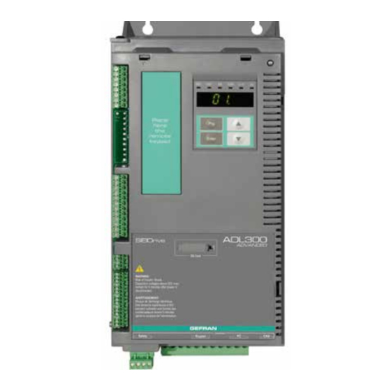
2.3 Identification of components The inverter converts the constant frequency and voltage of an existing three-phase network into DC voltage, from which it obtains a new three-phase network with variable voltage and frequency. With this variable three-phase network the speed of three-phase asynchronous and synchronous motors can be controlled continuously. 1. -
Page 11: Product Identification
2 = size 2 5 = size 5 Model A = Advanced B = Basic Inverter, ADL300 series Data plate Firmware and card revision plate Serial number Gefran S.p.A Via G.Carducci,24 I-21040-Gerenzano(VA) Firmware HW release 09012345 Prod. Drive model Release CONF... -
Page 12: Standard Configurations
2.5 Standard configurations ADL300A (Advanced) ADL300B - (Basic SinCos) Regulation card (R-ADL300-A , RC-ADL300-A) Regulation card (R-ADL300-B , RC-ADL300-B, R-ADL300-BS , RC-ADL300-BS) Display card (KB-ADL300) Display card (KB-ADL300) I/O expansion card (EXP-IO-...) Feedback expansion card (EXP-DE-... , EXP-SE) ADL300B - (Basic Endat) ADL300B - (Basic VGA) Regulation card (R-ADL300-BA, RC-ADL300-BA, R-ADL300-BAS, RC-ADL300-BAS) Regulation card (R-ADL300-C) - Page 13 ADL300 Advanced Type / Description Code R-ADL300-A Basic regulation card RC-ADL300-A Regulation card with integrated CAN EXP-IO-D4-ADL S567L 2 digital inputs + 2 digital outputs EXP-IO-D5R3-F-ADL ...
- Page 14 Regulation card ADL300 Basic Description Code ADL300B-xxxx-KBL-4 ADL300B-xxxx-KBL-2T R-ADL300-B S5DL01 8 + 1 Enable ADL300B-xxxx-KBL-2M ADL300B-xxxx-KBL-F-4-C ADL300B-xxxx-KBL-F-2T-C RC-ADL300-B S5DL03 8 + 1 Enable ADL300B-xxxx-KBL-2M-C ADL300B-xxxx-KBL-4-24 R-ADL300-BS S5DL20 8 + 1 Enable ...
-
Page 15: Transport And Storage
3 - Transport and storage Correct transport, storage, erection and mounting, as well as careful operation and maintenance are essential for proper and safe operation of the equipment. Protect the inverter against physical shocks and vibration during transport and storage. Also be sure to protect it Caution against water (rainfall) and excessive temperatures. -
Page 16: Specification
4 - Specification 4.1 Environmental Conditions Installation location �������������������� Pollution degree 2 or lower (free from direct sunligth, vibration, dust, corrosive or inflammable gases, fog, vapour oil and dripped water, avoid saline environment) Installation altitude �������������������� Max 2000m (6562 feet) above sea level. With 1.2% reduction in output current for every 100 m starting from 1000 m. -
Page 17: Input Electrical Data
4.4 Input electrical data Choke ������������������������������� Sizes 1...3: Optional (DC or AC), sizes 4-5 : integrated (DC) Note! See chapter 5.2 for THD values in accordance with EN 12015 and for selection of external inductances. Size Input Input Overvoltage Undervoltage Effective input current I DC-Link voltage... -
Page 18: Output Electrical Data
4.5 Output electrical data Maximum output voltage U2 �������������� 0.98 x U = AC input voltage) Maximum output frequency f2 ������������� 300 Hz The derating factors shown in the table below are applied to the rated DC output by the user. They are not automati- cally implemented by the drive: Idrive = In x K Size Rated output current... -
Page 19: Derating Values In Overload Condition
4.5.1 Derating values in overload condition In overload conditions the output current depends on the output frequency, as shown in the figure below. Figure 4.5.1-A: Ratio between overload/output frequency (ADL300-...-4 - ADL300-...-2T) Sizes 1...3 (4...22kW) Sizes 4-5 (30...75kW) OL (% I ) OL (% I ) F out (Hz) F out (Hz) -
Page 20: Voltage Level Of The Inverter For Safe Operations
4.6 Voltage level of the inverter for safe operations The minimum time between the moment in which an ADL inverter is disabled from the mains and that in which an operator can operate on internal parts of the inverter, without the danger of electric shock, is 5 minutes. This value takes into account the time to turn off an inverter supplied at 460 V + 10%, without any options (time indicated for disabled inverter condition). -
Page 21: Cooling
4.8 Cooling All inverters are equipped with internal fans. Size Fan capacity Minimum cabinet opening for (Heat dissipation) cooling =230...460V Heat sink (m Internal (m ADL300-...-4, 3ph 1040 1055 2 x 58 2075 2 x 58 2110 2 x 35 3150 2 x 98 3185... -
Page 22: Weights And Dimensions
4.9 Weights and dimensions Figure 4.9.1: Size 1 dimensions 135.5 23.6 23.5 (6.38) (5.33) (0.93) (0.93) (5.53) 11.5 SCALA 2:1 SCALA 2:1 SCALA 2:1 (4.53) 148.1 (5.83) Dimensions: Width x Height x Depth Weight Sizes (mm) (inches) (kg) (lbs) ADL300.- 1040/1055-...-4 162 x 343 x 159 6.38 x 13.50 x 6,26 12.8... - Page 23 Figure 4.9.3: Size 3 dimensions (9.25) 11.5 155.8 23.6 33.5 (6.61) (6.13) (0.93) (1.32) (6.61) (3:5) (3:5) (3:5) (6.46) 218.3 (8.59) Dimensions: Width x Height x Depth Weight Sizes (mm) (inches) (kg) (lbs) ADL300.- 3150/ 3185/ 3220-...-4 ADL300.- 3075/3110-...-2T 235 x 401 x 179.4 9.25 x 15.79 x 7.06 10.5 23.15...
- Page 24 Figure 4.9.5: Size 5 dimensions 304.8 (12.24) (12) (11.69) 30 38.5 (7.48) (3:5) (10.43) Dimensions: Width x Height x Depth Weight Sizes (mm) (inches) (kg) (lbs) ADL300.- 5550/5750-...-4 311 x 767 x 331.4 12 x 30.2 x 13.05 132.3 ADL300.- 5300/5370-...-2T ADL300 •...
-
Page 25: Options
5 - Options 5.1 Optional external fuses 5.1.1 Network side fuses (F1) The inverter must be fused upstream on the network side. Use fast-acting fuses only. F1 - External network side fuses EUROPE AMERICA DC link capacitor hours of Size service life [h] Type Code... -
Page 26: Input Chokes
5.2 Input chokes The three-phase mains choke is strongly recommended in order to: limit the RMS input current of the ADL300 inverter. increase the life of intermediate circuit capacitors and reliability of input diodes. reduce mains harmonic content reduce problems due to power supply via a low impedance line (≤ 1%). In accordance with EN 12015 (THD values <... -
Page 27: Ac Output Chokes
16 [35.3] ADL300-...-2M, 1ph 1011 1015 2022 For information please contact the Gefran Sales Office. 2030 3040 3055 Note! With the inverter operated at the rated current and a frequency of 50 Hz, the output chokes cause a voltage drop of approx. 2% of the output voltage. -
Page 28: External Braking Resistors (Optional)
5.4 External braking resistors (optional) Recommended combinations for use with internal braking unit. Table 5.4.1: Recommended combination ADL...-AC and ADL...-BR series List and technical data of standard external resistors Max. overload, 1" Max. overload, 30" Dimensions: Weight Size Resistor type Code Q.ty - service 10%... -
Page 29: Emc Filter (Optional)
5.5 EMC Filter (optional) The ADL300-...-F-4/2T inverters are equipped with an internal EMI filter, optional external filters are reported in the table. Weight Conducted emissions according to / Dimensions: Size Type Code Motor cable length Width x Height x Depth (mm) (kg) ADL300-... -
Page 30: Mechanical Installation
6 - Mechanical installation The Drive must be mounted on a wall that is constructed of heat resistant material. While the Drive is operating, the temperature of the Drive’s cooling fins can rise to a temperature of 158° F (70°C). Le drive doit être monté... -
Page 31: Fastening Positions
6.2 Fastening positions Fissaggio a muro • Wall mounting • Fixation mural • Wandmontagee • Fijación en pared 23.5 (5.53) (0.93) 23.5 (0.93) (5.53) 33.5 (1.32) (6.61) Taglia 1 Taglia 2 Taglia 3 Size 1 Size 2 Size 3 Grandeur 1 Grandeur 2 Grandeur 3 Größe 1... - Page 32 Recommended screws for fastening Size 1 (ADL300...-1...) 4 x M5 x 12 mm screws + Grover (spring-lock) washer + flat washer Size 2 (ADL300...-2...) 4 x M5 x 12 mm screws + Grover (spring-lock) washer + flat washer Size 3 (ADL300...-3...) 4 x M5 x 12 mm screws + Grover (spring-lock) washer + flat washer Size 4 (ADL300...-4...) 4 x M6 x 16 mm screws + Grover (spring-lock) washer + flat washer...
-
Page 33: Wiring Procedure
7 - Wiring Procedure Adjustable frequency drives are electrical apparatus for use in industrial installations. Parts of the Drives are energized during operation. The electrical installation and the opening of the device should therefore only be carried out by qualified personnel. Improper installation of motors or Drives may therefore cause the failure of the device as Warning! well as serious injury to persons or material damage. - Page 34 Functioning of the Drive without a ground connection is not permitted. To avoid disturbances, the armature of the motor must be grounded using a separate ground connector from those of other appliances. Caution Défense de faire fonctionner le drive sans qu’il y ait eu raccordement de mise à la terre préalable. Pour éviter les perturbations, la carcasse du moteur doit être mise à...
-
Page 35: Power Section
7.1 Power section 7.1.1 Cable cross-sections Terminals: L1 - L2 - L3 - BR - C1 - C - D - U - V - W - EM Size Maximum cable cross-section Recommended Recommended Tightening ADL300-...-4, (flexible conductor) stripping terminal torque (min) (mm) (mm) -
Page 36: Connection Of Shielding (Recommended)
Note! The power terminal strip is extractable on sizes 2055 ... 3110. The EM terminal strip is extractable on all mechanical sizes. Terminals: on structural work Size Cable cross-section Recommended Lock screw diameter Tightening torque (min) ADL300-...-2T, terminal (mm) (mm) (Nm) Same as the maximum cross-section used for the 2055 ... -
Page 37: Emc Guide Line
Use power shield kit to connect shield of motor cable to drive. Note! For further information regarding electro-magnetic compatibility standards, according to Directive 2014/30/EC, conformity checks carried out on Gefran appliances, connection of filters and mains inductors, shielding of cables, ground connections, etc., consult the “Electro-magnetic compatibility guide” on the CD attached to this drive. -
Page 38: Block Diagram Of Power Section
7.1.4 Block diagram of power section This type is equipped with an EMI input filter (models ADL300.-...-F-..; except ADL300-...-2M), an AC/DC converter, a system for pre-loading DC capacitors, a DC/AC converter, a power supply unit and an integrated braking unit. To manage emergency situations (drive power failure) the unit also envisages connection of an emergency unit between terminals EM and D. -
Page 39: Internal Emc Filter (Standard)
7.1.5 Internal EMC filter (standard) The ADL300.-...-F-.. series of inverters are equipped with an internal EMI filter (optional for the ADL300-...-2M series) able to guarantee the performance levels required by EN 12015, first environment, with max 10 m of shielded motor cable. -
Page 40: Motor Connection
7.1.8 Motor connection L1 L2 L3 BR C1 C V W EM L1 L2 L3 BR1 BR2 C ADL.-1040...3220-4 ADL.- 4300...5550 ADL.-2055...3110-2T ADL.- 4150...5300 3 ph 3 ph L1 L2 L3 C L1 L2 BR C1 C V W EM ADL.- 5750-4 ADL.-5370-2T... -
Page 41: Regulation Section
7.2 Regulation section Figure 7.2.1-A: Identification of cards and terminals (ADL300A) (RC-ADL300A only) R-ADL300A card RC-ADL300A card (RS232) Keypad (RS485/422) EXP-I/O-... card EXP-DE-... card EXP-SE-... card EXP-EN-... card EXP-HIP-... card Figure 7.2.1-B: Identification of cards and terminals (ADL300B) (RC-ADL300B-.. only) (RS232) Keypad (RS485/422) -
Page 42: Cable Cross-Sections
7.2.1 Cable cross-sections Maximum cable cross-section Recommended stripping Tightening torque (min) Terminals (AWG) (mm) (Nm) 0.2 ... 2.5 (1 cable) 26 ... 12 T5, T3, T2, T1 0.2 ... 0.75 (2 cables) 26 ... 19 0.2 ... 1.5 (1 cable) 26 ... - Page 43 Figure 7.2.2-B: terminal strip and connection ADL300B-2M and ADL300A with EXP-IO-D54R3-F-ADL card RO 30 Contactor RO 3C RO 20 Brake Contactor RO 2C RO 1O Drive ON RO 1C Emergency Failure MltSpd S1 Digital Input 5X MltSpd S0 Digital Input 4X Emergency mode Digital Input 3X StartRevCmd...
-
Page 44: Feedback Connection
Standard = +24V OUT; +24V IN/OUT versions on request; (**) Cards with +24V external power supply (+24V IN/OUT versions) must be separated from the external power supply with an external diode. Check if the diode is already present on the external power supply. Figure 7.2.3: Recommended card wiring 7.2.3 Feedback Connection This section describes the feedback connections for the ADL300B series. - Page 45 (1) Connection SinCos encoder + 2 Freeze (SESC) Technical specification: Channels ������������������������������� A+ A-, B+ B-, Z+ Z-, Sin+ Sin-, Cos+ Cos-, differential Management of loss of encoder signals. Max frequency �������������������������� 200 kHz (check the number of encoder impulses according to the maximum speed) Number of impulses ����������������������...
- Page 46 (2) Connection sinusoidal encoder 3 Channels + 2 Freeze (SE) Technical specification: Channels ������������������������������� A+ A-, B+ B-, Z+ Z-, differential Management of loss of encoder signals. Max frequency �������������������������� 200 kHz (check the number of encoder impulses according to the maximum speed) Number of impulses ����������������������...
- Page 47 (3) Connection EnDat Encoder + 2 Freeze (EnDat-SSi) Technical specification: Channels ������������������������������� A+ A-, B+ B-, differential Management of loss of encoder signals. Max frequency �������������������������� 200 kHz (check the number of encoder impulses according to the maximum speed) Number of impulses ���������������������� min 128, max 16384 (automatic recognition at initialisation) Electrical interface ������������������������...
- Page 48 (4) Connection EnDat Encoder Full Digital + 2 Freeze Technical specification: Programmable internal power supply ���������� min +5.2 V, max +6.1 V (default + 5.2 V) − Imax 150 mA. The internal power supply of the encoder can be selected from the keypad (ENCODER CONFIG menu, parameter Encoder supply (PAR 2102) to balance the loss of voltage due to the length of the encoder cable and load current.
- Page 49 (5) Connection digital encoder 3 Channels + 2 Freeze (TTL Line Driver / push pull) (DE) Technical specification: Channels ������������������������������� A+ A-, B+ B-, Z+ Z-, differential line drivers. Management of loss of encoder signals (via software). Max frequency �������������������������� 100 kHz (check the number of encoder impulses according to the maximum speed) Number of impulses ����������������������...
- Page 50 (7) Connection Sinusoidal SinCos Encoder + repetition (ADL300B-...-AD1) (SESC) Technical specification (XE): Channels ������������������������������� A+ A-, B+ B-, Z+ Z-, Sin+ Sin-, Cos+ Cos-, differential Management of loss of encoder signals. Max frequency �������������������������� 200 kHz (check the number of encoder impulses according to the maximum speed) Number of impulses ����������������������...
-
Page 51: Integrated Safety Card Connection
(8) Repeat Encoder (TTL line-driver) ADL300B-...-E24R have an incremental encoder output with TTL Line Driver levels (according to the main encoder supply) to be used to repeat the servomotor feedback device. This function is performed via HW and an encoder output can be repeated with a programmable divider. -
Page 52: Connection Diagrams
7.3 Connection diagrams Note! This chapter describes the typical wiring diagrams with reference to ADL300 drives with standard configuration. 7.3.1 Regulation potentials, digital I/O Figure 7.3.1.1: Regulation potentials (ADL300A) Shielded cable Analog input 1 Shielded cable Analog output 1 Analog input 2 Chassis Analog output 2 Chassis... -
Page 53: Typical Connection Diagram
7.3.2 Typical connection diagram Figure 7.3.2.1: Typical connection diagram (ADL300A-1040 ...3220 sizes) 3 Phase Mains (optional) OPTIONAL BREAKING RESISTORS Internal Keypad KEYPAD / DCP R-ADL V1 W1 ILIM OPTIONAL RS232 Enter ADL300A P-ADL EXP-ENC EXP-IO BRAKE DRIVE DOOR CONTACTOR CONTACTOR V2 W2 Emergency Failure... - Page 54 Figure 7.3.2.3: Typical connection diagram ADL300.-2M Single Phase Mains OPTIONAL BREAKING RESISTORS Internal Keypad KEYPAD / DCP R-ADL ILIM OPTIONAL RS232 Enter ADL300.-...-2M P-ADL EXP-ENC EXP-IO BRAKE DRIVE DOOR CONTACTOR CONTACTOR V2 W2 Emergency Failure Safety chain TRAFO BRAKE ADL300 • Quick installation guide - Specifications and connection...
-
Page 55: Emergency Connection Diagram (With Ups Or Ems Module)
7.3.3 Emergency connection diagram (with UPS or EMS module) The configuration described in this paragraph can be used to manage the motor in an emergency power failure condition (with 230 VAC single-phase UPS power supply or EMS module). Figure 7.3.2.4: Emergency connection diagram (ADL300A-4300 ...4450 sizes) 3 PHASE MAINS 1ph, 230V 50Hz... - Page 56 Figure 7.3.2.5: Emergency connection diagram (ADL300A-1040 ...3220 sizes) 3 PHASE MAINS 1ph, 230V 50Hz (optional) KEYPAD / DCP Internal Keypad BREAKING R-ADL V1 W1 ILIM RESISTORS RS232 Enter ADL300A P-ADL EXP-ENC EXP-IO EMS (*) Battery Pack EMERGENCY MODE SUPPLIER Safety OPTIONAL chain BRAKE...
- Page 57 Figure 7.3.2.6: Emergency connection diagram (ADL300-...-2M-1011 ...3055 sizes) SINGLE PHASE MAINS 1ph, 230V 50Hz Internal Keypad BREAKING KEYPAD / DCP R-ADL RESISTORS ILIM OPTIONAL RS232 Enter DC CHOKE ADL300.-2M P-ADL EXP-ENC EXP-IO OPTIONAL EMS (*) Battery Pack EMERGENCY MODE SUPPLIER Safety chain TRAFO...
- Page 58 To use this type of connection reference should be made to the safety and installation instructions in the "SAFETY MANUAL" (file: x08051ko-Safety User Manual-1_0r_IT and x08051ko-Safety User Manual-1_0r_EN on the CD-ROM supplied with the inverter or downloadable from the www.gefran.com website). Warning!
- Page 59 Diagram of a lift system complying with EN81-20 5.9.2.5.3 d, without contactors and STO integrated safety function (EN61800-5-2- SIL3). Figure 7.3.2.8-A: Contactorless connections (Asynchronous motor) 3 Phase Mains SYSTEM CONTROL UNIT CONTACTORLESS K4 (*) OK (*) Contactor check-up Commands (optional) OPTIONAL BREAKING RESISTORS...
-
Page 60: Connection Diagram For Emergency Maneuver (For Synchronous Motor Only)
To use this type of connection reference should be made to the safety and installation instructions in the "SAFETY MANUAL" (file: x08051ko-Safety User Manual-1_0r_IT and x08051ko-Safety User Manual-1_0r_EN on the CD-ROM supplied with the inverter or downloadable from the www.gefran.com website). Warning! 7.3.4 Connection diagram for emergency maneuver (for synchronous motor only). -
Page 61: Serial Interface (Pc Connector)
7.4 Serial interface (PC connector) Funzione / Function Interfaccia elettr./ Elect. Interface PIN 1 – – PIN 2 RS232 PIN 3 RS232 PIN 4 – – PIN 5 0V (Ground) – Alimentazione / Supply PIN 6 – – – PIN 7 PIN 8 –... -
Page 62: Can Interface
Connection to a PC with RS232 port (not isolated) The following are required for connection: • a shielded cable (code 8S8F59) for connection to the RS232 PC port of the drive to the RS232 connector of the PC, see figure 7.4.1-B. Connection to a PC with USB port (not isolated) The following are required for connection: •... -
Page 63: Optional Keypad Interface (Keypad Connector)
7.6 Optional Keypad interface (keypad connector) Keypad connector (XS1) Several devices can be connected to the multifunction keypad connector (9-pin D-SUB receptacle connector XS1) and are automatically recognised and managed. 1) Optional KB-ADL keypad (default connection) The keypad is supplied with a 40 cm-long cable, for longer distances, a 1:1 non-crossover cable must be used (9 shielded cables, e.g. -
Page 64: Braking
7.8 Braking There are various possible types of braking: Internal Braking Unit Injection of direct current from the Inverter into the motor (D.C. braking) There are two essential differences between the two braking methods: A braking unit can be used for speed reduction (e.g.: from 1000 to 800 rpm), whereas D.C. braking can only be usedfor braking to standstill. - Page 65 Size (Ω) ADL300-...-2M, 1ph 1011 1015 2022 2030 15.5 3040 3055 Braking unit rated current, duty cycle = 50% Peak current that can be delivered for max 60 seconds Minimum braking resistance value Table 7.8.2: Braking unit intervention threshold @ 480 V @ 460 V @ 400 V @ 230 V...
-
Page 66: Use Of The Keypad
8. Use of the keypad This chapter describes the integrated keypad and the optional KB-ADL keypad and methods of use for displaying and programming inverter parameters. 8.1 Description of keypads 8.1.1 KB-ADL300 integrated keypad → ILIM ← Drive status indicator LEDs →... -
Page 67: Kb-Adl Optional Programming Keypad
8.1.2 KB-ADL optional programming keypad → Drive status indicator LEDs ILim 01 MONITOR ← 02 DRIVE INFO 03 STARTUP WIZARD 04 DRIVE CONFIG 5-line x 21 character alphanumerical LCD display 05 LIFT DISP → Membrane keypad SAVE CUST FIND The optional programming keypad is used to display the status and diagnostics parameters during operation. It has a strip of magnetic material on the back so that it can be attached to the front of the drive or other metal surface (e.g. -
Page 68: Navigating With The Integrated Keypad
8.2 Navigating with the integrated keypad 8.2.1 Scanning of first and second level menus First level 01 . 23.8 8. 02.88. First level menus are shown by 2 digits. First level Second level .8 8. 0 5. 0 1 Enter Second level menus are shown by 4 digits separated by a point. - Page 69 Note ! Flashing points and characters in grey. E.g.: Synchronous list, Menu 19.6 - FUNCTIONS / PADS, PAR 3726 Ramp down limit = 2147418112 : 8 8. .00. . 26. Enter Enter (x13) Enter The point flashes, the bottom window is displayed ...
-
Page 70: Changing Values
E.g., float parameters: Synchronous list, MOTOR DATA, PAR 2002 Rated current = 22,4 A 14 . 20. 02. Enter Enter the flashing point of the second digit from the left displays the middle window E.g., BIT parameters: Synchronous list, Menu 1 - MONITOR, 1066 Enable state mon = 1 ... -
Page 71: Error Messages When Modifying A Parameter
• Modifying Enum values When you press Enter on an Enum value, the first digit on the right flashes. Use the arrow keys to scroll all the enum values of that parameter cyclically. Press Enter again to accept the value. Press Prg to reject the value and restore the previous value. -
Page 72: Displaying And Resetting Alarms
8.2.6 Displaying and resetting Alarms Note ! The alarms are shown on the display of the integrated keypad with the abbreviated text shown in brackets "[XXX]" in chapter "10.1 Alarms" on page 88 . Active alarms are displayed by a flashing indicator. Alarms that have been removed but not yet reset are fixed. -
Page 73: Motor Self-Tuning
8.2.8 Motor self-tuning Set PAR 2024 Autotune still to On to enable motor self-tuning. The firmware will automatically reset it to Off. The following warning messages are displayed at the start and end of Self-tuning: Operations displayed on the optional keypad Operations displayed on the integrated keypad Close Enable input C EN... -
Page 74: Navigating With The Optional Keypad
8.3 Navigating with the optional keypad 8.3.1 Scanning of the first and second level menus First level 23 ALARM LOG 01 MONITOR 01 MONITOR 02 DRIVE INFO 02 DRIVE INFO 03 STARTUP WIZARD 03 STARTUP WIZARD 04 DRIVE CONFIG 04 DRIVE CONFIG 05 LIFT 01 MONITOR... -
Page 75: Scanning Of The Parameters
8.3.3 Scanning of the parameters 01 MONITOR 01 MONITOR 01 MONITOR 02 DRIVE INFO 01/20 PAR: 20/20 PAR: 1400 Di g ital output X mon 03 STARTUP WIZARD Output current 00000000010001 04 DRIVE CONFIG 05 LIFT 01 MONITOR 02/20 PAR: ... -
Page 76: How To Save Parameters
● LINK parameters The parameter may assume the number of another parameter as value. 11 DIGITAL OUTPUTS 11 DIGITAL OUTPUTS 11 DIGITAL OUTPUTS 11 DIGITAL OUTPUTS 14 MOTOR DATA 01/16 PAR: 1410 01/16 PAR: 1410 01/16 PAR: 1410 15 ENCODER CONFIG Di g output 1X s r c Di g output 1X s r c... -
Page 77: Configuration Of The Display
8.3.8 Configuration of the display 8.3.8.1 Language selection Menu 04 DRIVE CONFIG, parameter 04.19 Language select, PAR: 578, default=English. This is used to set one of the languages available: English, Italian, French, German, Spanish and Turkish. 01 MONITOR 04 DRIVE CONFIG 04 DRIVE CONFIG 04 DRIVE CONFIG 02 DRIVE INFO... -
Page 78: Messages
8.3.12 Messages Operator messages are displayed with this page. There are two types of messages: - timed (closed automatically after a certain number of seconds), - permanent (continue to be displayed until the operator presses the ESC key). Several concurrent messages are enqueued and presented to the operator in sequence, starting from the most recent. Message Default parameters 0001H-1... -
Page 79: Load Parameters From Keypad
If an error occurs during transfer, the following message is displayed: Message Save par failed Code: Press ESC to exit The code XX indicates the type of error, see paragraph 10.3. To exit the error message, press the ESC key. 8.3.13.3 Load parameters from keypad Menu 04 DRIVE CONFIG, parameter 04.15 Load par from keypad, PAR: 592. -
Page 80: Asynchronous/Synchronous Selection
8.3.15 Asynchronous/Synchronous selection • To switch from Asynchronous to Synchronous: Menu 4 - DRIVE CONFIG, PAR 6100 Load synch control 01 MONITOR 04 DRIVE CONFIG Load synch control? 02 DRIVE INFO 19/19 PAR: 6100 03 STARTUP WIZARD Load synch control Press E to exe c ute Press E to execute 04 DRIVE CONFIG... -
Page 81: Commissioning Via Keypad
9 - Commissioning via keypad Adjustable frequency drives are electrical apparatus for use in industrial installations. Parts of the Drives are energized during operation. The electrical installation and the opening of the device should therefore only be carried out by qualified personnel. Improper installation of motors or Drives may therefore cause the failure of the device as well as serious injury to persons or material Warning! damage. - Page 82 This equipment must not be used as an ‘emergency stop mechanism’ (see EN 60204, 9.2.5.4). Ne pas utiliser cet appareil en tant que « dispositif d’arrêt d’urgence » (cf. EN 60204, 9.2.5.4). Never open the device or covers while the AC Input power supplyis switched on. Minimum time to wait before working on the terminals or inside the device is listed in section 4.6.
-
Page 83: Asynchronous Motor Startup Wizard (With The Integrated Keypad)
9.1 Asynchronous motor startup wizard (with the integrated keypad) The ADL300 can operate with regulation modes: Voltage/Frequency (SSC) , Sensorless (open loop) and field-oriented vector control (closed loop). Note! Before starting, check the factory settings: Menu 02 DRIVE INFO, parameter 02.2 Control type, PAR: 480, default=11. .88. - Page 84 Step 2 - Setting motor parameters Note! Def: The factory (default) setting depends on the size of the drive that is connected. These values refer to the ADL..-1055-AC ▲ 401 v 3.8 8. 20.00. 4.0.0 Πo ▼ Enter Enter Enter (x2) Enter (x3s) Prg 399 v...
- Page 85 (4) Once the drive is enabled the autotune procedure starts. This may take a few minutes, depending on the type of motor being used. (5) At the end of the procedure the following screen is displayed. After opening the Enable contact, go to step 4 ...
- Page 86 ▲ 1 kg . 54. ▼ Enter Enter 0 kg Enter (x3s) Prg ▲ 1 kg ▼ Enter Enter Enter (x3s) Prg 0 kg ▲ 1 kg . 58. ▼ Enter Enter Enter (x3s) Prg 0 kg ▲...
- Page 87 Next proceed to step 9 to save the system parameters that have been entered and those calculated by the drive using the autotune and automatic phasing procedures. Step 9 - Save parameters To save the new parameter settings, so that they are maintained also after power-off, proceed as follows: 85 5 0 S A v E Enter...
-
Page 88: Asynchronous Motor Startup Wizard (With The Optional Keypad)
9.1 Asynchronous motor startup wizard (with the optional keypad) The ADL300 can operate with regulation modes: Voltage/Frequency (SSC) , Sensorless (open loop) and field-oriented vector control (closed loop). Note! Before starting, check the factory settings: Menu 02 DRIVE INFO, parameter 02.2 Control type, PAR: 480, default=11. 01 MONITOR 02 DRIVE INFO 02 DRIVE INFO... - Page 89 Step 1 - Electrical connections Make the connections as described in paragraph 7.3.2. Checks to be performed before powering the drive • Check that the supply voltage is correct and that the input terminals on the drive (L1, L2 and L3) are connected correctly.
- Page 90 Note! When data entry is complete the Take parameters command is executed automatically (menu 14 MOTOR DATA, PAR: 2020). The motor data entered during the STARTUP WIZARD procedure are saved in a RAM memory to enable the drive to perform the necessary calculations. These data are lost if the device is switched off.
- Page 91 ▲ 5.3 A PAR: 2102 PAR: 2102 Encoder supply Encoder supply ▼ 0000005.2 5.1 A Def: Def: Step 5 – Encoder phasing Not available in this mode. Step 6 - Setting the maximum speed reference value and system speed Setting the maximum speed reference value: this defines the maximum motor speed value (in rpm) that can be reached with each single reference signal (analog or digital).
- Page 92 ▲ 1 kgm² PAR: 11160 PAR: 11160 Motor inertia Motor inertia ▼ 000000000 kgm² 0 kgm² kgm² Def: Def: After setting the mechanical measurements, proceed to the next step. Step 8 - Setting application parameters The application data can be entered at this stage. ●...
- Page 93 ● Set the ramp values ▲ 0.6 m/s³ PAR: 11040 PAR: 11040 Acc start jerk Acc start jerk ▼ 00000000.5 m/s³ 0.4 m/s³ m/s³ Def: Def: ▲ 0.7 m/s² PAR: 11042 PAR: 11042 Acceleration Acceleration ▼ 00000000.6 m/s² 0.5 m/s²...
- Page 94 (1) Press the E key to start the save parameters procedure. (2) Press E to confirm (3) End of procedure (4) When the parameters have been saved correctly the drive displays this screen to show that the startup wizard is complete.
-
Page 95: Startup Wizard For Brushless Motors (With The Integrated Keypad)
9.2 Startup wizard for brushless motors (with the integrated keypad) The ADL300 can operate with regulation modes: field-oriented vector control of permanent magnet synchronous mo- tors (brushless). Note! Before starting, check the factory setting: Menu 02 DRIVE INFO, parameter 02.2 Control type, PAR: 480, default=12. .88. - Page 96 Step 2 - Setting motor parameters Note! Def: The factory (default) setting depends on the size of the drive that is connected. These values refer to the ADL..-1055-BR ▲ 341 v 3.8 8. 20.00. 3.4.0 Πo ▼ Enter Enter Enter (x2) Enter (x3s) Prg+ 339 v...
- Page 97 Step 4 - Setting encoder parameters (Standard card EXP-SESC-I1R1F2-ADL) The incorrect configuration of the encoder tension can permanently damage the device; therefore, it is advisable to check the values on the encoder’s specification plate. Caution ▲ 2049 ppr 21. 00. 20.4.8 ▼...
- Page 98 Step 7 - Setting the system weights The system weights must be entered in this part of the wizard procedure. ▲ 1 kg uE IG ▼ Enter Enter Enter Enter (x3s) Prg 0 kg ▲ 1 kg . 52. ▼...
- Page 99 ● Set the distance value ▲ . 04. ▼ Enter Enter ● Enable the inertia and gains of the speed loop calculation ▲ ▼ Enter Enter Next proceed to step 9 to save the system parameters that have been entered and those calculated by the drive using the autotune and automatic phasing procedures.
-
Page 100: Startup Wizard For Brushless Motors (With The Optional Keypad)
9.2 Startup wizard for brushless motors (with the optional keypad) The ADL300 can operate with regulation modes: field-oriented vector control of permanent magnet synchronous mo- tors (brushless). Note! Before starting, check the factory setting: Menu 02 DRIVE INFO, parameter 02.2 Control type, PAR: 480, default=12. 01 MONITOR 02 DRIVE INFO 02 DRIVE INFO... - Page 101 Step 1 - Electrical connections Make the connections as described in paragraph 7.3.2. Checks to be performed before powering the drive • Check that the supply voltage is correct and that the input terminals on the drive (L1, L2 and L3) are connected correctly.
- Page 102 Step 3 - Autotune with motor at stand-still or coupled to the load The drive carries out the motor autotune procedure (real measurement of motor parameters). Autotuning may take a few minutes. Note! If this operation generates an error message (e.g. Error code 1), check the connections of the power and control circuits (see step 1 - Connections), check the motor data settings (see...
- Page 103 Auto t une Auto t une 03 STARTUP WIZARD PAR: 2192 Progress 0% Progress 10% Run phasing still? Autotune still Press E to exe c ute Close Enable in p ut Press ESC to abort E=Yes Down=Next Auto t une Auto t une Progress 100% Done...
- Page 104 ▲ 1 kg PAR: 11156 PAR: 11156 Cable weight Cable weight ▼ 000000000 0 kg Def: Def: ▲ 1 kgm² PAR: 11158 PAR: 11158 Reducer inertia Reducer inertia ▼ 000000000 kgm² 0 kgm² kgm² Def: Def: ▲ 1 kgm² PAR: 11160 PAR: 11160...
- Page 105 ▲ 0.7 m/s² PAR: 11042 PAR: 11042 Acceleration Acceleration ▼ 00000000.6 m/s² 0.5 m/s² m/s² Def: Def: ▲ 1.5 m/s³ PAR: 11044 PAR: 11044 Acc final jerk Acc final jerk ▼ 00000001.4 m/s³ 1.4 m/s³ m/s³ Def: Def: ▲...
- Page 106 Final check Note! If you wish to use the inertia value calculated by the converter, you should copy the parameter value 5.4.20 CalcInertia (PAR 12020, Menu LIFT/ MECHANI- CAL INFORMATION) in parameter 16.20 Inertia, PAR: 2240. Menu 5.4 MECHANICAL DATA, parameter 5.4.20 CalcInertia, PAR: 12020, default=(S). 5.4 MECHANICAL DATA 01 MONITOR 5.1 SPEED...
-
Page 107: Troubleshooting
10 - Troubleshooting 10.1 Alarms Note ! To reset alarms, see paragraphs "8.2.6 Displaying and resetting Alarms" on page "8.3.11 Alarms" on page . In the following table, the Code is visible only from serial line Code Error message shown Sub-code Description on the display [on the... - Page 108 Code Error message shown Sub-code Description on the display [on the integrated keypad] Solution: - Change the processing cycle. - Use a cooling fan to cool the motor. Condition: Drive overload alarm. Drive overload [DOL] - The inverter output current has exceeded the allowed overload value. - The overload cycle has exceeded the allowed values.
- Page 109 Code Error message shown Sub-code Description on the display [on the integrated keypad] OV safety Condition: Safety status alarm caused by Overvoltage situations. [OVSF] Solution: the firmware attemps to reset the card automatically. If the condition is removed (the alarm cleared message is displayed) the alarm can be reset and the drive restarted by deactivating and reactivating Enable and Start.
- Page 110 Solution: Contact Gefran in order to update the firmware on the optional encoder card. Condition: an optional card has been removed with respect to the configuration present when the last Save parameters command was executed or there Opt cfg change [OCFG] is a fault on the optional card or on the regulation card.
-
Page 111: Speed Fbk Loss Alarm According To The Type Of Feedback
10.2 Speed fbk loss alarm according to the type of feedback Note ! For the correct interpretation of the cause of the alarm trigger, it is necessary to transform the hex code indicated in parameter 15.13 SpdFbkLoss code, PAR 2172 , in the corresponding binary and verify in the encoder table that the active bits and related description are used. Example with encoder Endat: PAR 2172 = A0H (hex value) - Page 112 ● Speed fbk loss [22] alarm with EnDat absolute encoder Value Name Description 0x08 MOD_INCR Cause: voltage level not correct or disturbance on signals of incremental channels A-B. Solution: Check the connection of the the encoder-drive channels A-B, check the connection of the screen, check the encoder supply voltage, check parameter 2102 Encoder supply, check parameter 2108 Encoder signal Vpp.
-
Page 113: Reset Speed Fbk Loss Alarm
Cause: Firmware on option card incompatible with firmware on regulation card. 0x200 error When this has been signalled the information obtained from the encoder is not reliable. Solution: Contact Gefran in order to update the firmware on the optional card. ADL300 • Quick installation guide - Specifications and connection... -
Page 114: Messages
10.3 Messages Note ! For more information see chapter 8.7. Index Error message shown on Sub-code Description the display [on the inte- grated keypad] Condition: may occur during loading of the parameter database saved in flash Load default param [LDEF] normally appears in the following conditions: at initial power-on when a new firmware version is downloaded, when the regulation is installed on a new size, when the region is changed. - Page 115 Index Error message shown on Sub-code Description the display [on the inte- grated keypad] Incorrect incremental encoder impulse count or incorrect absolute encoder impulse count probably caused by an incorrect value of the pole pairs parameter or a load applied to the motor. Solution: Check the value of the pole pairs parameter, check whether a load is applied Incorrect incremental encoder impulse count probably caused by the incorrect value of the encoder impulse parameter.
- Page 116 [KEYF] xxxxH-x Solution: Ask Gefran to supply the correct key to enable the desired firmware function. Key expiring Condition: this may occur at drive power-on if the incorrect enabling key was inserted for a given firmware function. At this stage the firmware function...
-
Page 117: Appendix
Appendix A.1 - ADL300 Advanced Configuration ADL300 is coded as the Advanced version and does not implement any I/O or encoder expansion cards. The user may integrate any of the available options, to meet specific system requirements (an I/O card must always be present to use the drive). -
Page 118: Inserting Expansion Cards
A.1.1 - Inserting expansion cards • Slot 1: dedicated to I/O cards (EXP-IO-...-ADL) • Slot 2: dedicated to encoder expansion cards (EXP-DE-ADL, EXP-SE-ADV, etc.) Slot 1 Slot 2 Remove the top cover: insert a screwdriver into the holes at the top of the plastic card cover and push gently Raise the cover as shown in the figure. -
Page 119: I/O Card
A.2 - I/O Card ● EXP-IO-D4-ADL 1 enable input (Enable) + 2 digital inputs (DI) + 2 digital outputs (DO) EXP-IO-D4-ADL -- 26 27 28 29 10 11 12 ● EXP-IO-D5R3-F-ADL 1 enable input (Enable) + 5 digital inputs (DI) + 3 relay outputs (RO). The terminals of this card are not extractable. - Page 120 ● EXP-IO-D8R4-ADL The digital I/O integrated in the ADL300B is recognised as this expansion card. 1 enable input (Enable) + 8 digital inputs (DI) + 4 relay outputs (RO) EXP-IO-D8R4-ADL 50 51 52 53 54 55 56 57 10 11 12 ●...
- Page 121 ● EXP-IO-D16R4-ADL 1 enable input (Enable) + 12 digital inputs (DI) + 4 digital outputs (DO) + 4 relay outputs (RO) EXP-IO-D16R4-ADL 50 51 52 53 54 55 56 57 20 21 22 23 24 25 26 27 28 29 10 11 12 ADL300 •...
-
Page 122: Input/Output Features
A.2.1 Input/Output features 24V DC power supply Tolerance ± 10% Maximum current 150 mA Isolation 1 KV ● Digital inputs (DI) and enable hardware inputs (EN-HW) Description Features Type 24 V PNP / NPN Operating voltage 0 V to + 24 V (+ 30 V max) Load 5 mA @ +24 V - R = 4.7 kΩ... - Page 123 Precision 1% of full scale Isolation AI-X AI-X AI-X (*) Select input V/I (V=OFF, I=ON) Fast Input Inputs (Freeze) ● Description Features Type 24VDC PNP Input Input voltage +24VDC ±20% Load 8mA @ 24V, RL = 2,7kΩ Thresholds < 2V, V >...
- Page 124 ● Analog reference outputs (±10) Description Features Type Single-ended in voltage Operating voltage ± 10 V = 5 kΩ (max 10 mA) Load 5 mA @ ± 10 V - R Precision 1% of full scale Isolation Short-circuit protection +10V +10V - 10V - 10V...
-
Page 125: Encoders And Encoder Expansion Cards
A.3 Encoders and encoder expansion cards A.3.1 Encoders Encoders provide motor speed and position feedback The regulation algorithms in the ADL300 drive are capable of controlling asynchronous and permanent magnet synchronous (brushless) motors. With asynchronous motors the regulation algorithm may or may not use the speed measurement obtained from the encoder reading. -
Page 126: Phasing
A.3.2 Phasing In order for the ADL300 Brushless regulation algorithm to function correctly, it is necessary to know the position of the rotor with respect to the stator power phases. Therefore the 0° position provided by the absolute encoder must be known with respect to the position of a motor pole and the encoder count direction must match the motor power phases. -
Page 127: Encoder Cards
A.3.3 Encoder cards Note ! The encoder power supply must be adequate considering the cable length and the absorption rates as shown in table (1) at the end of this chapter. EXP-DE-I1R1F2-ADL Digital Incremental Encoder. This is the default card supplied with drives to control asynchronous motors in field- oriented flux vector mode (FOC). - Page 128 INCREMENTAL DIGITAL ENCODER (DE) SINGLE ENDED NPN O.C. 0VE out +VE out INCREMENTAL DIGITAL ENCODER (DE) SINGLE ENDED PNP O.C. 0VE out +VE out (*) Connection of shielding, see figure 7.2.4 ADL300 • Quick installation guide - Specifications and connection...
- Page 129 EXP-DE-I1-ADL Digital Incremental Encoder. EXP-DE-I1-ADL 10 11 12 13 14 15 (TTL Line-driver) Channels ������������������������������� A+ A-, B+ B-, differential line drivers, optoisolated. Max frequency �������������������������� 200 kHz (check the number of encoder impulses according to the maximum speed) Number of impulses ���������������������� min 128, max 16384 (default 1024) Electrical interface ������������������������...
- Page 130 INCREMENTAL DIGITAL ENCODER (DE) SINGLE ENDED NPN O.C. 0VE out +VE out INCREMENTAL DIGITAL ENCODER (DE) SINGLE ENDED PNP O.C. 0VE out +VE out (*) Connection of shielding, see figure 7.2.4 ADL300 • Quick installation guide - Specifications and connection...
- Page 131 EXP-SE-I1R1F2-ADL Incremental Sinusoidal Encoder (SE). EXP-SE-I1R1F2-ADL 20 21 22 23 10 11 12 13 14 15 Channels ������������������������������� A+ A-, B+ B-, Z+ Z-, differential. Management of loss of encoder signals Max frequency �������������������������� 200 kHz (check the number of encoder impulses according to the maximum speed) Number of impulses ����������������������...
- Page 132 EXP-SESC-I1R1F2-ADL Incremental Sinusoidal Encoder + absolute SinCos (SESC). This is the default card supplied in drives to control permanent magnet synchronous motors (Brushless - SESC). EXP-SESC-I1R1F2-ADL 20 21 22 23 10 11 12 13 14 15 Channels ������������������������������� A+ A-, B+ B-, Z+ Z-, Cos+ Cos-, Sin+ Sin-, differential Management of loss of encoder signals.
- Page 133 EXP-SESC-I1R1-V-ADL Incremental Sinusoidal Encoder + absolute SinCos (SESC). EXP-SESC-I1R1-V-ADL Channels ������������������������������� A+ A-, B+ B-, Z+ Z-, Cos+ Cos-, Sin+ Sin-, differential Management of loss of encoder signals. Max frequency �������������������������� 200 kHz (check the number of encoder impulses according to the maximum speed) Number of impulses ����������������������...
- Page 134 EXP-EN/SSI-I1R1F2-ADL Incremental sinusoidal + Absolute EnDat/SSI (EN/SSI). This is the default card supplied in drives to control permanent magnet synchronous motors (Brushless - SESC). EXP-EN/SSI-I1R1F2-ADL 20 21 22 23 10 11 12 13 14 15 Channels ������������������������������� A+ A-, B+ B-, differential Management of loss of encoder signals.
- Page 135 EXP-EN/SSI-I1R1F2-ADL (EnDat FULL DIGITAL) Incremental sinusoidal + Absolute EnDat Full Digital. This is the default card supplied in drives to control permanent magnet synchronous motors (Brushless - SESC). EXP-EN/SSI-I1R1F2-ADL 20 21 22 23 10 11 12 13 14 15 Power supply ����������������������������...
- Page 136 EXP-HIP-I1R1F2-ADL Incremental Sinusoidal Encoder + Hiperface absolute (HIP) EXP-HIP-I1R1F2-ADL 20 21 22 23 10 11 12 13 14 15 Incremental channels ���������������������� A+ A-, B+ B-, differential Management of loss of encoder signals. Max frequency �������������������������� 200 kHz (check the number of encoder impulses according to the maximum speed) Number of impulses ����������������������...
- Page 137 Repeat Encoder RE (TTL/HTL line-driver) Encoder expansion cards have an incremental encoder output with TTL/HTL Line Driver levels (according to the main encoder supply) to be used to repeat the servomotor feedback device. This function is performed via HW and an encoder output can be repeated with a programmable divider.
-
Page 138: Brake Monitoring System (A3 Amendment)
A.4 - Brake monitoring system (A3 Amendment) A.4.1 Introduction The brake monitoring function in the ADL series of products: ADL300 enables implementation of the automatic brake monitoring function as required by EN81-1 A.3 §9.11.3. Two functional elements are required to implement the brake monitoring function: 1. -
Page 139: Configuration Of The Brake Fault Alarm
A.4.2 Configuration of the brake fault alarm • Activation of the brake fault alarm function. The installer must have previously located the necessary digital inputs of the ADL drive and connected the correspond- ing wires to the feedback signals on these inputs. Note that depending on the type of wiring arrangement, the brake feedback signals are normally asserted (brake closed –... - Page 142 Ph. +91 20 6614 6500 Fax +44 (0) 8452 604556 Fax +91 20 6614 6501 sales@gefran.co.uk gefran.india@gefran.in SENSORMATE AG GEFRAN MIDDLE EAST ELEKTRIK VE GEFRAN INC. ELEKTRONIK SAN. VE TIC. LTD. STI Steigweg 8, 8 Lowell Avenue Yesilkoy Mah. Ataturk...
Need help?
Do you have a question about the installationSIEIDrive ADL300 and is the answer not in the manual?
Questions and answers