Table of Contents
Advertisement
OPERATOR'S MANUAL
CADD-Legacy
PLUS
™
Ambulatory Infusion Pump
Model 6500
CONTINUOUS OR INTERMITTENT
DELIVERY
This online version differs
from the printed version.
Certain information that is
not intended for patients has
been removed.
This Operator's Manual is for clinician use only.
Read the entire Operator's Manual before
operating the pump.
S I M S D E L T E C , I N C .
i
Advertisement
Table of Contents

Related Manuals for SIMS Deltec CADD-Legacy PLUS


Summary of Contents for SIMS Deltec CADD-Legacy PLUS
- Page 1 OPERATOR’S MANUAL CADD-Legacy PLUS ™ Ambulatory Infusion Pump Model 6500 CONTINUOUS OR INTERMITTENT DELIVERY This online version differs from the printed version. Certain information that is not intended for patients has been removed. This Operator’s Manual is for clinician use only. Read the entire Operator’s Manual before operating the pump.
- Page 2 The issue date of this Operator’s Manual is included on the back cover for the clinician’s information. In the event one year has elapsed between the issue date and product use, the clinician should contact SIMS Deltec, Inc. to see if a later revision of this manual is available.
-
Page 3: Warnings
Read this entire Operator’s Manual before operating the CADD-Legacy ™ ambulatory infusion pump. Failure to properly follow warnings, cautions, and instructions could result in death or serious injury to the patient. Warnings • This Operator’s Manual should be used by clinicians only. Do not permit patients to have access to this manual, as the informa- tion contained would allow the patient complete access to all programming and operating functions. - Page 4 syringe to the pump’s displayed values such as RES VOL and GIVEN in order to determine whether under-delivery of medica- tion is occurring and if necessary, take appropriate action. • System delivery inaccuracies may occur as a result of back pressure or fluid resistance, which depends upon drug viscosity, catheter size, and extension set tubing (for example, microbore tubing).
- Page 5 • Do not disclose to the patient the pump’s security codes or any other information that would allow the patient complete access to all programming and operating functions. • Do not use rechargeable NiCad or nickel metal hydride (NiMH) batteries. Do not use carbon zinc (“heavy duty”) batteries. They do not provide sufficient power for the pump to operate prop- erly.
-
Page 6: Cautions
• Do not prime the fluid path with the tubing connected to a patient as this could result in overdelivery of medication or air embolism. • Ensure that the entire fluid path is free of all air bubbles before connecting to the patient to prevent air embolism. •... - Page 7 • Do not use the pump in the vicinity of magnetic resonance imaging (MRI) equipment. • Do not use the pump near ECG equipment. • Do not sterilize the pump. • Do not use the pump in the presence of flammable anesthetics or explosive gases.
- Page 8 viii...
-
Page 9: Table Of Contents
Table of Contents Warnings Cautions Section 1: General Description Introduction ................Indications ................. Epidural/Subarachnoid Administration ........Symbols ..................Pump Diagram ................Description of the Keys, Display, and Features ......The Main Screen ................ Lock Levels ................Security Codes ................Lock Level Table ............... 10 Section 2: Pump Setup and Programming Installing or Replacing the Batteries ........... - Page 10 Section 3: Operating the Pump Starting the Pump ..............43 Stopping the Pump ..............43 Turning the Pump On/Off ............44 Resetting Reservoir Volume ............44 Section 4: Biomed Functions Overview: Accessing the Biomed Functions ....... 45 Air Detector On/Off ..............46 Upstream Sensor On/Off ............
-
Page 11: Section 1: General Description
Section 1: General Description General Description Introduction The CADD-Legacy ™ PLUS ambulatory infusion pump provides measured drug therapy to patients in hospital or outpatient settings. Therapy should always be overseen by a physician or a certified, licensed healthcare professional. As appropriate to the situation, the patient should be instructed in using and troubleshooting the pump. - Page 12 Section 1: General Description Anesthetics Administration of anesthetics to the epidural space is limited to use with indwelling catheters specifically indicated for short-term drug delivery. WARNING: • Do not administer drugs to the epidural space or subarachnoid space unless the drug is indicated for administration to those spaces.
-
Page 13: Symbols
Section 1: General Description Symbols Alternating Current (Power Jack) Accessory Jack Attention, consult accompanying documents (read Instructions for Use) Class II Equipment Type CF Equipment Splashproof – water splashed against pump housing will have no harmful effects (see Cleaning the Pump and Accessories, Section 5, for additional important informa- tion) Date of Manufacture... -
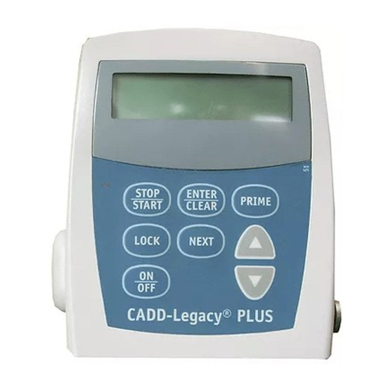
Page 14: Pump Diagram
Section 1: General Description Pump Diagram Display Power Jack Accessory Jack Front AC Indicator View Light Air Detector Keypad ® Cassette Power Jack symbol Threaded Accessory Mounting Jack symbol Hole Battery Rear Compartment View Cassette Lock... -
Page 15: Description Of The Keys, Display, And Features
Section 1: General Description Description of the Keys, Display, and Features AC Indicator Light The green indicator light is on when you are using the AC adapter to power pump. Display The Liquid Crystal Display (LCD) shows programming information and messages. In this manual, the term “display” is synonymous with display panel or LCD. - Page 16 Section 1: General Description Power Jack You may plug an AC Adapter into the Power jack as an alternate source of power. The indicator light on the front of the pump will illuminate when the AC Adapter is in use. Accessory Jack This jack is used for accessory cables.
- Page 17 Section 1: General Description protect against unregulated gravity infusion that can result from an improperly attached cassette. Unregulated gravity infusion could result in death or serious injury to the patient. Threaded Mounting Hole The optional Polemount Bracket Adapter attaches to the threaded mounting hole in the back of the pump, allowing you to hang the pump on an IV pole.
-
Page 18: The Main Screen
Section 1: General Description occlusions could result in death or serious injury to the patient. Downstream Occlusion Sensor: The pump contains a downstream occlusion sensor. When a downstream occlusion (between the pump and patient access site) is detected, an alarm will sound, delivery will stop, and the display will show “High Pressure.”... -
Page 19: Lock Levels
Section 1: General Description Lock Levels Lock levels are used to limit patient access to certain programming and operating functions. The table on the next page lists the func- tions that are accessible in Lock Level 0 (LL0), Lock Level 1 (LL1), and Lock Level 2 (LL2). -
Page 20: Lock Level Table
Section 1: General Description Lock Level Table This table lists the operations that are accessible in each lock level while the pump is stopped and running. LL0 permits complete access to all programming and operating functions. LL1 permits limited control of pump programming and operations. LL2 permits only minimal control pump operations. -
Page 21: Section 2: Pump Setup And Programming
Section 2: Pump Setup and Programming Pump Setup and Programming Installing or Replacing the Batteries Use new, AA alkaline batteries such as DURACELL ® EVEREADY ® ENERGIZER ® batteries. The pump retains all pro- grammed values while the batteries are removed. Dispose of used batteries in an environmentally safe manner, and according to any regulations which may apply. - Page 22 Section 2: Pump Setup and Programming In order to install or replace the batteries, be sure the pump is Stopped. Then, follow these steps: 1. Push down and hold the arrow button while sliding the door off. 2. Remove the used batteries. Pulling on the end of the battery strap will make battery removal easier.
- Page 23 Section 2: Pump Setup and Programming • Use two new, AA alkaline batteries to power the pump. You ® may use any alkaline batteries, including DURACELL Alkaline and EVEREADY ® ENERGIZER ® Alkaline, for example. 4. Place the battery door over the battery compartment and slide the door closed.
- Page 24 Section 2: Pump Setup and Programming WARNING: If a gap is present anywhere between the battery door and the pump housing, the door is not properly latched. If the battery door becomes detached or loose, the batteries will not be properly secured; this could result in loss of power, nondelivery of drug, and, depending on the type of drug being administered, death or serious injury to the patient.
- Page 25 Section 2: Pump Setup and Programming 6. Resume operation of the current program by pressing and ⁄ holding to start the pump or proceed to program the pump. NOTE: • The life of the batteries is dependent on the amount of medication delivered, delivery rate, battery age, and the temperature.
-
Page 26: Watching Power Up
Section 2: Pump Setup and Programming Watching Power Up When you install the batteries, the pump will start its power up sequence during which it performs self-tests and displays pro- grammed values. Watch for the following: • Pump model number and last error code (“LEC”) if any, will appear. -
Page 27: Changing To Lock Level 0 (Ll0)
Section 2: Pump Setup and Programming Changing to Lock Level 0 (LL0) Before programming the pump, make sure the pump is set to LL0. LL0 allows the clinician to access all programming and operating functions. Π1. Make sure the pump is stopped. Press . -
Page 28: Programming The Pump: General Instructions
Section 2: Pump Setup and Programming Programming the Pump: General Instructions The procedure for changing a programmed setting is similar for most programming screens. • Make sure the pump is stopped and in Lock Level 0. • To begin programming, start at the main screen and press „... -
Page 29: Delivery Methods
Section 2: Pump Setup and Programming Delivery Methods ™ The CADD-Legacy PLUS pump has two delivery methods, and provides delivery in milliliters per hour: • Continuous Delivery Mode (up to 125 ml per hour) • Intermittent Delivery Mode (up to 125 ml per hour) The Continuous Delivery Mode (CDM) permits a steady infusion rate. -
Page 30: Programming Screens For Continuous Delivery
Section 2: Pump Setup and Programming Programming Screens for Continuous Delivery CADD-Legacy ™ These are the programming screens for the PLUS pump, in the continuous delivery mode. Descriptions of the screens follow. Reservoir Volume Reservoir Volume 100.0 Continuous Rate Continuous Rate (ml/hr) ml/hr Given... - Page 31 Section 2: Pump Setup and Programming Continuous Rate Enter the continuous rate of medication delivery (in ml/hr). The maximum rate is 125 ml/hr. Given This screen shows the total amount of drug delivered since the last time the value was cleared. The amount shown is rounded to the nearest 0.05 ml.
-
Page 32: Programming Continuous Delivery
Section 2: Pump Setup and Programming Programming Continuous Delivery Be sure the pump is in the continuous delivery mode versus the intermittent delivery mode. To program the pump, enter the pre- scribed values. 1. Begin at the main screen. • Make sure the pump is in LL0. •... - Page 33 Section 2: Pump Setup and Programming or off. WARNING: When the Air Detector is turned off, the pump will not detect air in the fluid path. Periodically inspect the fluid path and remove any air to prevent air embolism. Air embolism could result in serious injury or death to the patient.
-
Page 34: Programming Screens For Intermittent Delivery
Section 2: Pump Setup and Programming Programming Screens for Intermittent Delivery These are the programming screens for the CADD-Legacy ™ PLUS pump, in the intermittent delivery mode. Descriptions of the screens follow. Reservoir Volume Reservoir Volume 100.0 ml Dose Volume Dose Volume Dose Duration Dose Duration... - Page 35 Section 2: Pump Setup and Programming Air Detector (Off, Air Detector On-High, or On-Low) On-High Upstream Sensor Upstream Sensor (Off or On) Reservoir Volume Enter the volume of fluid contained in a filled fluid container. The Reservoir Volume value decreases as the pump delivers fluid or as you prime the tubing.
- Page 36 Section 2: Pump Setup and Programming Dose Cycle The cycle is the time from the start of one dose to the start of the next dose. The programmable values for cycle are based on the Dose Duration. There must be at least 5 minutes between the end of one dose and the start of the next;...
- Page 37 Section 2: Pump Setup and Programming Given This screen shows the total amount of drug delivered since the last time this value was cleared. The amount shown is rounded to the nearest 0.01 ml. If this value reaches 99999.95, it automatically returns to 0 and continues counting.
-
Page 38: Programming In The Intermittent Delivery Mode
Section 2: Pump Setup and Programming Programming in the Intermittent Delivery Mode Be sure the pump is in the intermittent delivery mode versus the continuous delivery mode. To program the pump, enter the pre- scribed values. 1. Begin at the main screen. •... - Page 39 Section 2: Pump Setup and Programming „ • Press 5. Enter the Dose Cycle. ´ Î • Press to select the desired cycle. ¤ • Press „ • Press 6. Enter the KVO rate. ´ Î • Press to select the desired KVO rate. ¤...
- Page 40 Section 2: Pump Setup and Programming WARNING: When the Air Detector is turned off, the pump will not detect air in the fluid path. Periodically inspect the fluid path and remove any air to prevent air embolism. Air embolism could result in death or serious injury to the patient.
-
Page 41: Removing A Cassette
Section 2: Pump Setup and Programming Removing a Cassette WARNING: Close the fluid path tubing with the clamp before removing the cassette from the pump to prevent unregulated gravity infusion, which could result in death or serious injury to the patient. 1. -
Page 42: Attaching A Cassette
Section 2: Pump Setup and Programming Attaching a Cassette Obtain a new, filled Medication Cassette ™ Reservoir, or CADD ® Administration Set attached to a non-vented, flexible IV bag. WARNING: For detailed instructions and warnings pertaining to ™ ® the Medication Cassette Reservoir or CADD Administration Set, please refer to the instructions for use supplied with the product for... - Page 43 Section 2: Pump Setup and Programming 4. Insert a coin into the lock, push in, and turn counterclock- wise until the line on the lock lines up with the arrow on the side of the pump and you feel the lock click into place. WARNING: Attach the cassette (the part of the Medication ™...
-
Page 44: Priming The Tubing And Connecting To The Patient
Section 2: Pump Setup and Programming Priming the Tubing and Connecting to the Patient The pump must stopped and in LL0 or LL1 in order to prime the fluid path. If the pump is in LL2, you cannot prime the fluid path. NOTE: If you are not changing the fluid container but wish to prime the fluid path, you may follow the same procedure. - Page 45 Section 2: Pump Setup and Programming ‹ NOTE: Each time you press and hold , you pump a maximum of 1.0 ml of fluid into the tubing. The pumping action will stop automatically when 1.0 ml has been deliv- ered. If all of the air has not been removed from the fluid path, repeat the above priming procedure.
-
Page 46: Inserting The Tubing Into The Air Detector
Section 2: Pump Setup and Programming Inserting the Tubing into the Air Detector WARNING: When the Air Detector is turned off, the pump will not detect air in the fluid path. Periodically inspect the fluid path and remove any air to prevent air embolism. Air embolism could result in death or serious injury to the patient. - Page 47 Section 2: Pump Setup and Programming 3. To seat the tubing into the groove, gently pull the tubing, until it is under the retention nubs and flat in the groove. Retention nubs 4. Connect the tubing to the patient’s infusion set or indwell- ing catheter.
-
Page 48: Setting The Lock Level For The Patient
Section 2: Pump Setup and Programming Setting the Lock Level for the Patient The Lock Level must be changed to LL1 or LL2 to prevent the patient from having complete access to all programming and oper- ating functions. NOTE: You may change the lock level at any time by stopping the pump and following the procedure below. -
Page 49: Cdm: Programming With Upper Limits, Adjusting Rate In Lock Level 1
Section 2: Pump Setup and Programming CDM: Programming with Upper Limits, Adjusting Rate in Lock Level 1 This feature may be used in the continuous delivery mode only. If a prescription allows for the Continuous Rate to be adjusted during the course of therapy, you may wish to operate the pump in LL1. -
Page 50: Idm: Stopping The Pump During The Dose
Section 2: Pump Setup and Programming IDM: Stopping the Pump During the Dose Stopping the pump while a dose is in progress will shift all subse- quent doses by the amount of time the pump is stopped. Pump is stopped subsequent for 10 doses shift by... - Page 51 Section 2: Pump Setup and Programming Level 0 or Lock Level 1. The Dose Remaining screen with the remaining hours and minutes of the dose will be displayed, followed by the “Dose Starts in” screen. Reprogram the “Dose Starts in” screen, which will cancel the remainder of the dose, and the next cycle will start after the delay you selected.
- Page 52 Section 2: Pump Setup and Programming...
-
Page 53: Section 3: Operating The Pump
Section 3: Operating the Pump Operating the Pump Starting the Pump When you start the pump, programmed values will be automatically reviewed. Then fluid delivery will begin as programmed, and “RUN” will appear on the main screen. If the pump will not start, a message will appear on the display. -
Page 54: Turning The Pump On/Off
Section 3: Operating the Pump Three sets of dashes will appear one-by-one on the pump’s display, each accompanied by a single beep. ⁄ 2. Release after the third set of dashes appears and the pump beeps. Turning the Pump On/Off When the pump is stopped, you may put the pump into a low power state by turning it off. -
Page 55: Section 4: Biomed Functions
Section 4: Biomed Functions Biomed Functions Overview: Accessing the Biomed Functions The Biomed Functions are pump configurations that are less fre- quently changed. The Biomed Functions are accessible only when the pump is stopped and in Lock Level 0. To Access the Biomed Functions Œ... -
Page 56: Air Detector On/Off
Section 4: Biomed Functions Air Detector On/Off The Air Detector screen can be set to On-High, On-Low, or Off. WARNING: When the Air Detector is turned off, the pump will not detect air in the fluid path. Periodically inspect the fluid path and remove any air to prevent air embolism. -
Page 57: Upstream Sensor On/Off
Section 4: Biomed Functions Upstream Sensor On/Off The Upstream Occlusion Sensor screen can be set to On or Off. If this screen is set to On, and an upstream occlusion (between pump and fluid container) is detected, an alarm will sound, delivery will stop, and the display will show “Upstream Occlusion.”... -
Page 58: Changing The Delivery Method
Section 4: Biomed Functions Changing the Delivery Method Delivery can be changed between Continuous Delivery and Intermit- tent Delivery. This allows for either continuous drug delivery or infusion of a prescribed volume of a drug over a specified time period. When the delivery method is changed, programming will revert to default settings. -
Page 59: Section 5: Reference
Section 5: Reference Reference Messages and Alarms, Alphabetical List Messages and Alarms Description / Corrective Action Air In Line The Air Detector has detected air in the Detected fluid path; the fluid path may contain air bubbles, or the tubing may not be fully TONE ALARM threaded through the Air Detector. - Page 60 Section 5: Reference Messages and Alarms Description / Corrective Action [No message] With no AC adapter attached, the batteries have been removed while the TONE ALARM pump is running. The pump is now stopped and unpowered. Install batteries to silence the alarm. Batteries were removed within approxi- mately 15 seconds after stopping the pump.
- Page 61 Section 5: Reference Messages and Alarms Description / Corrective Action Motor Locked, Batteries are depleted and the pump was remove all power powered up with the AC Adapter. Install new AA batteries, reconnect the AC TONE ALARM adapter, and restart the pump. The disposable (CADD ®...
- Page 62 Section 5: Reference Messages and Alarms Description / Corrective Action The Reservoir Volume is low. Change the ResVol Low fluid container soon. See Reservoir Volume Alarm in Section 1 for more HREE SINGLE BEEPS information. Service is due for this pump based on Service Due clock battery age or total motor revolu- TONE ALARM...
-
Page 63: Cleaning The Pump And Accessories
Section 5: Reference Cleaning the Pump and Accessories CAUTION: • Do not immerse the pump in cleaning fluid or water. Do not allow solution to soak into the pump, accumulate on the keypad, or enter the battery compartment. Moisture build-up inside the pump may damage the pump. - Page 64 Section 5: Reference Cleaning the Battery Contacts Routinely clean the battery contacts, possibly as part of the preven- tative maintenance cycle, to remove buildup of foreign material on the contacts. Use the following to clean the battery contacts: • Cotton swab wetted with Isopropyl Alcohol (70% mini- mum) NOTE: Do not use an alcohol formulation that contains components other than alcohol and water.
-
Page 65: Exposure To Radiation, Ultrasound, Magnetic Resonance Imaging (Mri), Or Use Near Ecg Equipment
Section 5: Reference Exposure to Radiation, Ultrasound, Magnetic Resonance Imaging (MRI), or Use near ECG Equipment CAUTION: • Do not expose the pump to therapeutic levels of ionizing radiation as permanent damage to the pump’s electronic circuitry may occur. The best procedure to follow is to remove the pump from the patient during therapeutic radiation sessions. -
Page 66: Technical Description
Section 5: Reference Technical Description Standards used in Development of the Pump The following standards were used in whole or part in the develop- ment of the pump. Medical Electrical Equipment IEC 60601-1, Medical Electrical Equipment, Part 1: General Re- quirements for Safety. -
Page 67: Specifications (Nominal)
Section 5: Reference IEC 61000-3-3, Voltage Functions and Flicker, only for devices powered @ 220 VAC or greater. IEC 61000-4-2, 8 kV contact discharge, 15 kV air discharge. IEC 61000-4-3, Radiated Susceptibility, 26 MHz to 2500 MHz, 10 V/m, 1 kHz – 80% AM modulation. IEC 61000-4-4, AC Fast Transients, at ±500 volts, ±1000 volts, and ±2000 volts –... - Page 68 Section 5: Reference Pump Alarms Low battery power; depleted battery ..... power; battery dislodged; pump stopped; pump fault; low reservoir volume; high delivery pressure; air in line; disposable not attached when run attempted; motor locked; upstream occlusion; reservoir volume empty; program incomplete; key stuck;...
- Page 69 Section 5: Reference System Storage Temperature -20°C to 60°C (-4°F to 140°F) ...... System Delivery Accuracy ± 6% (nominal). At low infusion rates, ......this accuracy may not be achieved for short periods. During the total infusion time, the accuracy averages out (see accuracy curves, pages 62 and 63) System Definition System is defined as a CADD-Legacy...
- Page 70 Section 5: Reference Continuous Delivery Mode Specifications Reservoir Volume 1 to 9999 or Not In Use; programmable ....in 1 ml increments, displayed in 0.1 ml increments Default: 1.0 ml Continuous Rate 0.1 to 125 ml/hr; programmable in ....0.1 ml /hr increments Default: 0.0 ml Given 0 to 99999.95 in 0.05 ml increments...
- Page 71 Section 5: Reference Given 0 to 99999.95 in 0.05 ml increments ........Dose Remaining 1 minute increments ....Biomed Functions Air Detector ....... On-Low On-High Default: On-High Upstream Sensor ....Default: On Delivery Mode Continuous ....Intermittent Default: Intermittent...
-
Page 72: Accuracy Test Results
Section 5: Reference Accuracy Test Results The following graphs are designed to show flow accuracy of the infusion system plotted against given time periods. Flow rate immediately following startup Time Interval: 0.5 min Total Time: 120 min Programmed Rate: 24.0000 ml/hr ®... - Page 73 Section 5: Reference Flow rate immediately following startup Time Interval: 15 min Total Time: 1500 min Programmed Rate: 0.1 ml/hr ® Cassette Used: CADD Administration Set with anti- siphon valve Flow (ml/hr) T (min) Short term flow rate error Programmed Rate: 0.1 ml/hr Average Flow Rate: 0.0989 ml/hr...
-
Page 74: Safety Features And Fault Detection
Section 5: Reference Safety Features and Fault Detection Hardware Safety Features Key hardware safety features include a watchdog timer circuit, motor driver and motor watchdog circuits, and a voltage detector circuit. Each safety circuit performs a unique function to insure the overall safety of the device. - Page 75 Section 5: Reference the motor. A unique feature of this circuit is that control lines to and from the microprocessor circuit allow the microprocessor to perform a complete functional test of the motor drive circuit with- out running the motor. The microprocessor performs this test function every several minutes to assure its continued functionality.
-
Page 76: Software Safety Features
Section 5: Reference Software Safety Features Hardware-related Software Safety Features Program Memory Check At power up and at regular intervals thereafter, the program memory is tested by calculating a Cyclic Redundancy Code (CRC) on the program and then comparing it with the CRC stored with the program. -
Page 77: Data Handling Software Safety Features
Section 5: Reference ‹ ⁄ switches for . The software must detect that both switches are activated before taking any action. Data Handling Software Safety Features Data Stored in RAM Before use, data associated with delivery and stored in RAM is tested by calculating a CRC on the data and then comparing it with the CRC stored with the data. -
Page 78: Annual Functional Inspection And Testing Procedures
Section 5: Reference two-tone audible alarm and stop all drug delivery. Annual Functional Inspection and Testing Procedures Deltec recommends annual functional inspections and tests on all ™ CADD-Legacy pumps. The following inspection and testing procedures should be performed annually to verify function and accuracy. -
Page 79: Testing Procedures
Section 5: Reference suitable tool. Care must be taken not to damage the pump housing or to incur further damage to the contacts. Mechanical Inspection • Press each key on the keypad. Each key should have a distinctive dome feeling. The keys should not feel flat. •... - Page 80 Section 5: Reference ful power up is indicated with six audible beeps and the “STOP” screen displayed. Continue with the lock check. Lock Check • Attach a 50 or 100 ml Medication Cassette ™ Reservoir or CADD ® Administration Set to the pump. The line on the lock should be aligned with the arrow on the side of the pump.
- Page 81 Section 5: Reference ‹ ‹ Release . Press and hold . While priming the tubing, listen to the motor for excessive noise or grinding sounds. Count the number of pump activations. The pump should prime ten double activations and then stop. Press „...
- Page 82 Section 5: Reference Activation Timing Check • Reprogram the Reservoir Volume to 1.0 ml and clear the Given screen. ⁄ • Press and hold until three dashed disappear from the display. The pump should sequentially display all of the programmed values. Start a timer at the first motor activa- tion.
- Page 83 Section 5: Reference • The pump should respond with a continuous two-tone alarm and the display should read “Air In Line Detected.” „ ⁄ • Press to silence the alarm and remove the empty Medication Cassette ™ Reservoir or CADD ®...
-
Page 84: Occlusion Pressure Range Tests
Section 5: Reference Occlusion Pressure Range Tests Occlusion Pressure Range Test I Description Pressure is generated by activating the pumping mechanism with an ™ attached filled, clamped Medication Cassette Reservoir. The pump is started and fluid is injected until the high pressure alarm sounds. Equipment needed ™... - Page 85 Section 5: Reference 7. The pump should alarm when the syringe is between 0.5 and 0.1 ml. Occlusion Pressure Range Test II Description An adjustable metered pressure source is connected to the Medication Cassette ™ Reservoir tubing. The pressure is slowly increased until the high pressure alarm sounds.
- Page 86 Section 5: Reference ™ 4. Connect the Medication Cassette Reservoir outlet tube to the metered pressure source. NOTE: Do not use a CADD ® Extension Set with Anti-Siphon Valve. 5. Start the pump and run at 50 ml/hr. 6. Slowly increase the backpressure, noting when the high pressure alarm is activated.
-
Page 87: Accuracy Tests
Section 5: Reference Accuracy Tests Gravimetric Accuracy Testing Description A Medication Cassette ™ Reservoir is partially filled with water and weighed, then attached to a pump that is set to deliver a certain amount of water. The Medication Cassette ™ Reservoir is then removed and weighed again. - Page 88 Section 5: Reference lock connector. 3. Secure the slide clamp as close to the extension set luer lock connector as possible. This should assure a minimum water loss from the tubing when the syringe is removed. 4. Weigh the entire Medication Cassette ™...
- Page 89 Section 5: Reference pump fails a second time, call SIMS Deltec or SIMS Graseby Ltd. Example: Predelivery Weight: 61.1 g Postdelivery Weight: – 41.6 g Weight of Amount Delivered: = 19.5 g Volume of Amount Delivered: 19.5 ml Intended Delivery Volume: –...
- Page 90 Section 5: Reference Volumetric Accuracy Testing Description A predetermined amount of water is delivered into a collection device such as a burette or graduated cylinder. The amount of water delivered is compared to the amount that the pump is programmed to deliver.
- Page 91 9. If the accuracy error percentage is greater than ± 6%, repeat ™ the test with a new Medication Cassette Reservoir. If the pump fails a second time, call SIMS Deltec or SIMS Graseby Ltd. Example: Actual Delivery Volume: 19.5 ml Intended Delivery Volume: –...
-
Page 92: Index
Section 5: Reference Biomed Functions Code, 9, 45 Index Bold page numbers indicate figure references cassette, 4, 6 attaching, 32 cautions, vi removing, 31 AC Adapter, 6, 7 warnings, v AC indicator light, 4 cassette lock, 4, 7, 33 accessory jack, 3, 4 cleaning pump, accessories, 53–54 accuracy tests, 62–63 cautions, vi... - Page 93 Section 5: Reference removing, 31 warnings, iv Reservoir Volume, 8, 10, 20, 22, indicator light, 4, 5 25, 28, 34, 51, 52, 58, 60 inspection procedures, 68 resetting, 44 Intermittent Delivery Mode, 19 safety features keypad, keys, 4, 5 hardware, 64 KVO rate, 19, 26, 60 software, 66–67 security codes...
-
Page 94: Limited Warranty
B. Warranty Performance Procedure: Notice of the claimed defect must be made in writing or by telephone to the Manufacturer as follows: SIMS Deltec 1265 Grey Fox Road, St. Paul MN 55112 U.S.A., 1-800-426-2448 or SIMS Graseby Ltd. WD2 4LG UK, +44 (0)1923 246434. - Page 95 Section 5: Reference E. Computer Program License: 1. The Pump is intended to be used in conjunction with a particular Licensed Computer Program supplied by Manufacturer and use of any other program or unauthorized modifi- cation of a Licensed Computer Program shall void Manufacturer’s warranty as set forth above.
- Page 96 U.S. Distribution: SIMS Deltec, Inc. 1265 Grey Fox Road St. Paul, Minnesota 55112 U.S.A. 1-800-426-2448 European Representative: SIMS Graseby Ltd. WD2 4LG UK +44 (0)1923 246434 © 2000 SIMS Deltec, Inc. All rights reserved. Printed in U.S.A. 2000-03 40-3934-51D...
Need help?
Do you have a question about the CADD-Legacy PLUS and is the answer not in the manual?
Questions and answers