
Related Manuals for WAGO CANopen 752


Summary of Contents for WAGO CANopen 752
- Page 1 Fieldbus Dependent I/O Module CANopen Manual Technical Description, Installation and Configuration 752-124/000-002 Version 1.0.0...
- Page 2 • General Copyright ã 2001 by WAGO Kontakttechnik GmbH All rights reserved. WAGO Kontakttechnik GmbH Hansastraße 27 D-32423 Minden Ph.: +49 (0) 571/8 87 – 0 Fax: +49 (0) 571/8 87 – 1 69 E-mail: info@wago.com Web: http://www.wago.com Technical Support Ph.: +49 (0) 571/8 87 –...
-
Page 3: Table Of Contents
Table of Contents • iii Table of Contents 1 Important Explanations................1 Legal Basis .....................1 1.1.1 Copyright ..................1 1.1.2 Personnel Qualification..............1 1.1.3 Intended Use ..................1 Scope of Validity..................2 Symbols....................2 Abbreviations ..................3 2 System Description..................4 Base Module...................5 Electronic Module ..................6 3 Technical Data ....................7 4 Installation ....................12 Mechanical Installation ................12 4.1.1... - Page 4 iv • Important Explanations 7 CANopen ....................28 Review....................28 Module properties ................29 Object Directory...................30 7.3.1 Communication Profile Area ............30 7.3.2 Manufacturer Specific Device Profile..........32 7.3.3 Standard Device Profile ..............33 7.3.4 Relation (Standard Mapping)............34 7.3.5 Transmission Type (Operating mode) ..........36 7.3.6 Inhibit Time..................36 7.3.7 Setting the COB-IDs ...............37 7.3.8...
-
Page 5: Important Explanations
WAGO Kontakttechnik GmbH. Please contact WAGO Kontakttechnik GmbH for any wishes in terms of a modified or a new hardware or software configuration. Fieldbus Dependent I/O Module... -
Page 6: Scope Of Validity
2 • Important Explanations 1.2 Scope of Validity This manual describes the fieldbus dependent I/O module of the WAGO-I/O-SYSTEM 752 for the CANopen. Components Article No. Electronic Module 752-327 Base Module, D-SUB 752-827 Base Module, MCS 752-828 1.3 Symbols Warning Observe this information in all cases to protect the system from damage. -
Page 7: Abbreviations
Digital Input Digital Input Module Digital Output Digital Output Module Electronic Data Sheets EMCY Emergency Objekt Input/Output Identifier Index WAGO MULTICONNECTOR SYSTEM Network Management Process Data Object Read Only Remote Transmit Request Receive PDO RxPDO Read/Write Service Data Object S-Idx... -
Page 8: System Description
2 System Description The WAGO-I/O-SYSTEM 752 for CANopen is part of the compact series of WAGO field bus nodes for distributed automation. It has a fixed number of digital inputs (DI) and digital outputs (DO) and transmits the signals to a higher ranking control system via CANopen. -
Page 9: Base Module
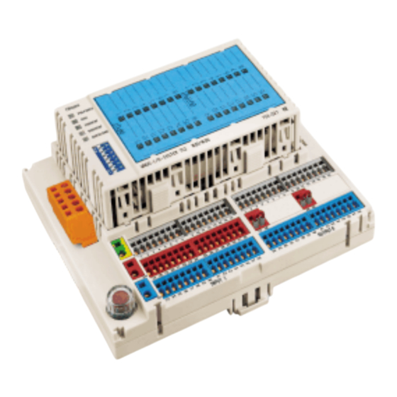
System Description • 5 2.1 Base Module The base module is the interface for all external wiring, including the fieldbus, power supply, and sensor/actuator connections. A multi-conductor connector links the external wiring to the plug-in electronic module. 10 11 12 13 14 15 16 10 11 12 13 14 15 16 17 18 19 20 21 22 23 24... -
Page 10: Electronic Module
Text can be added to the marking label using a permanent felt tip pen (order no. 210-110), or can be labeled by means of a plotter or a laser printer. The WAGO SCRIPT marking system has templates available for easy and profes- sional customization of marking labels. -
Page 11: Technical Data
Technical Data • 7 3 Technical Data CANopen System data Transmission medium Shielded Cu Cable Max. length of fieldbus 40 m ... 1000 m (depends on baud rate /on the cable) Baud rate 10 kBaud ... 1 MBaud Buscoupler connection 1 x D-SUB 9 (752-828) 1 x MCS (752-827), Connector (231-305/010- 000/050-000) is included... - Page 12 8 • Technical Data Wire connection ® Power supply CAGE CLAMP 0.08 mm² ... 2.5 mm², AWG 28-12* ® Sensors, actuators CAGE CLAMP 0.08 mm² ... 1.5 mm², AWG 28-16 ® Supply voltage for CAGE CLAMP outputs (8 circuit group) 0.08 mm²...
- Page 13 Technical Data • 9 Degree of Protection Degree of protection according to IP 20 protection against physical contact with EN 60 529 standard test probes Conformity and Certification Conformity labelling E175199, UL 508 Climatic Environmental Conditions Operating temperature 0 °C ... 55 °C Storage temperature -25 °C ...
- Page 14 30 dBµV/m (30 m) 37 dBµV/m Dimensions / Distances 155 mm 60 mm 8 mm PUSH PUSH CANopen PREPARED TXOVERF RXOVERF OVERLOAD WAGO-I/O-SYSTEM 752 16DI/16DO 752-327 INPUT I OUTPUT O PUSH PUSH CANopen PREPARED TXOVERF RXOVERF OVERLOAD WAGO-I/O-SYSTEM 752 16DI/16DO...
- Page 15 Technical Data • 11 Distances to building walls RH / LH: 0 mm Top: 20 mm Bottom: 20 mm Front: 0 mm when fitted 150 mm fitting space Attention The distances between I/O module(s) and building walls have to be observed in order to guarantee sufficient ventilation.
-
Page 16: Installation
4.1 Mechanical Installation 4.1.1 Snapping on / Detaching the Base Module The WAGO-I/O-SYSTEM 752 is intended for mounting on a TS35 type car- rier rail. The base module snaps onto the carrier rail. Fig. 4-1: Snapping the Base Module onto the carrier rail... -
Page 17: Insertion/Extraction Of The Electronic Module
Apply force at the positions marked "PUSH" when plugging in the electronic module. PUSH PUSH CANopen PREPARED TXOVERF RXOVERF OVERLOAD WAGO-I/O-SYSTEM 752 16DI/16DO 752-327 Fig. 4-3: Plugging in the Electronic Module g1x2802x The electronic module is correctly inserted when all four latches have en- gaged. Latch PUSH PUSH... -
Page 18: Dip Switch
PUSH CANopen PREPARED TXOVERF RXOVERF OVERLOAD WAGO-I/O-SYSTEM 752 16DI/16DO 752-327 Fig. 4-5: DIP Switch g1x2804x 4.1.4.2 Module ID The binary valency of the module ID set on the DIP switch increases towards the switch number, whereby a logic ´1´ is represented by an ´ON´. - Page 19 Installation • 15 4.1.4.3 Baud rate / Configuration Mode The baud rate is set in the configuration mode and is entered as a default value via the DIP switches 1 to 4. The module saves the setting if DIP switch 8 is switched over from ´OFF´...
-
Page 20: Electrical Installation
Fig. 4-6: How to operate the CAGE CLAMP g1xxx10x The WAGO-I/O-SYSTEM 752 requires a 24 V DC supply. The sensors supply voltage is short circuit protected by means of the plug-in fuse F1 (TR 5 / 250 V / 6.3A T). -
Page 21: Connection Of The Module Supply Voltage
Installation • 17 752-837 752-838 10 11 12 13 14 15 16 10 11 12 13 14 15 16 17 18 25 26 17 18 19 20 21 22 23 24 25 26 27 28 29 30 31 32 33 34 35 36 37 38 39 40 41 42 43 44 45 46 47 48 33 34 35 36 37 38 39 40 41 42 43 44 45 46 47 48... -
Page 22: Connection Of The Input Signals
18 • Installation 4.2.3 Connection of the Input Signals The input signal connection group is identified by the imprint "INPUT" on the base module. Three terminals are available for each digital input. The termi- nals for one input are shown superimposed. Vertical connection group for one channel Color Input... -
Page 23: Connection Of The Output Supply Voltage
Installation • 19 4.2.4 Connection of the Output Supply Voltage The supply voltage for the two output groups of 8 connections each can be provided either internally using the supply voltage for the module, or exter- nally from a separate power source. The base modules are provided with two sets of terminal blocks in the middle row of the output terminals. -
Page 24: Connection Of The Output Signals
When providing a separate output supply voltage to a group of 8 outputs, the supply voltage common must be terminated on the base module using the 0 V potential of the WAGO-I/O-SYSTEM 752 (blue terminal block). The entire current load is applied to the common terminal connection. If more than 6 Amps is applied to the common terminals, separate terminal blocks should be used. -
Page 25: Connection Of The Fieldbus Interface
210-312. Additionally, housing parts, test plugs with cable and male con- nectors for cable extensions are available from the MCS series (pin spacing 5.08 mm / 0.200 in). Please contact your local WAGO office or distributor for further information on the MCS series. -
Page 26: Cabling Of The Fieldbus
The data line should be routed separately from all high current carrying ca- bles. Note WAGO offers the screen connection system, series 790, for an optimum con- nection between the fieldbus cable screen and the function earth. As an option, the cable screen can be routed to the ´Shield´ plug pin. By means of an RC combination, the contact is connected to the function earth and as such with the carrier rail. - Page 27 Installation • 23 4.2.7.2 Termination Resistors Attention The bus cable must be terminated with a resistor (121 Ω / ±1% / ¼ W). The resistor is contacted with CAN_H and CAN_L. Should problems occur during commissioning, your first step should be to measure the resistance between CAN_L and CAN_H.
-
Page 28: Schematic Circuit Diagram
24 • Schematic Circuit Diagram 5 Schematic Circuit Diagram A basic representation of the input, output and supply circuitry are shown in the schematic circuit diagram. Actuator Fieldbus Sensor supply supply connection (1 ... 16) Jumper 6,3 A 100nF 100nF 24 V 100nF 100nF... -
Page 29: Status Indicators
PUSH PUSH CANopen PREPARED TXOVERF RXOVERF OVERLOAD WAGO-I/O-SYSTEM 752 16DI/16DO 752-327 Fig. 6-1: Status Indicators g1x2805x Fieldbus (CANopen) specific status indicators. Interference in the output circuit is displayed as a collective fault marked "OVERLOAD". Status LED’s for the inputs and outputs are integrated in the area of the marking label. -
Page 30: Output Status Indicators
26 • Status Indicators 6.2 Output Status Indicators The output status LED’s display the actual state of each output. They will not be illuminated in the event of a short circuit at the output or a missing supply voltage to the output drivers. Output value of the higher ranking Fault controls... -
Page 31: Overload Status Indicator
Status Indicators • 27 6.4 Overload Status Indicator The LED designated "OVERLOAD", when illuminated, indicates the presence of an output fault. Possible output faults: • Short circuit of one or more outputs • Missing supply voltage to the output drivers •... -
Page 32: Canopen
28 • CANopen 7 CANopen 7.1 Review CAN (Controller Area Network) was developed in the mid 1980s for data transmission in motor vehicles. The CAN specifications define the data link layer. This is the physical and data security layer, i.e. basically the means are described via which data transmission takes place. -
Page 33: Module Properties
CANopen • 29 7.2 Module properties The I/O Module from the WAGO-I/O-SYSTEM 752 for CANopen is sorted to server devices. The module supports the following functions: • CANopen Minimum Capability Device • Node Guarding • 2 Transmit (Tx-) PDO • 2 Receive (Rx-) PDO •... -
Page 34: Object Directory
30 • CANopen 7.3 Object Directory The Object directory is devided in three areas: • Communication Profile Area (Index 0x1000 - 0x1BFF) • Manufacturer Specific Profile Area (Index 0x2000 - 0x5FFF) • Standard Device Profile Area für DS-401 (from Index 0x6000) 7.3.1 Communication Profile Area S-Idx Name... - Page 35 CANopen • 31 S-Idx Name Type Attr. Default* / Presetting Meaning 0x1011 Restore default parameters Unsigned8 0x04 Number of restore options restore all default parameters Unsigned32 0x00000001 By writing the signature "load" (MSB 0x64 61 6F 6C LSB) the default parameter are loaded. They work after power on.
-
Page 36: Manufacturer Specific Device Profile
32 • CANopen S-Idx Name Type Attr. Default* / Presetting Meaning 0x1801 Transmit PDO Communication Unsigned8 2-4 / 0x03 Communication parameter Parameter 2. Tx-PDO Number of valid Sub-Indices COB-ID Unsigned32 0x00000280 + Node-ID COB-ID of 2. Tx PDO Transmission Type Unsigned8 0xFF transmission type defined in... -
Page 37: Standard Device Profile
CANopen • 33 7.3.3 Standard Device Profile 7.3.3.1 8-Bit digital input block, 0x6000 S-Idx Name Type Attr. Default Value Meaning 0x6000 Number Blocks 8 Inputs State Unsigned8 None Number of digital input blocks Read 8 Inputs 1 ... 8 Unsigned8 None 1. -
Page 38: Relation (Standard Mapping)
34 • CANopen 7.3.4 Relation (Standard Mapping) The relation of the application objects (Index 0x2000, 0x2100 and 0x5900) to the PDOs is different for Receive- (Rx-) and Transmit- (Tx-) PDOs. 7.3.4.1 Transmit PDO1 and 2 The Tx-PDO 1 is automatically defined according to Profile DS-401. TxPDO1 S-Idx Value... - Page 39 CANopen • 35 7.3.4.2 Receive PDO1 und 2 The first 2 Rx PDOs are automatically defined according to Profile DS-401. RxPDO1 S-Idx Value Description 1600 2 SubIndices are mapped 6200 01 08 Address 1. Digital output block (corresponds toObjekt 0x2100 0x01) 6200 02 08 Address 2.
-
Page 40: Transmission Type (Operating Mode)
36 • CANopen 7.3.5 Transmission Type (Operating mode) For each PDO a mode of transmission (in index communication parameter) can be defined. Digital inputs are transmitted by default with ´Change of Value´(COV). The kind of transmission dependent on the transmission type for digital inputs. Transmission PDO transmission Type... -
Page 41: Setting The Cob-Ids
CANopen • 37 7.3.7 Setting the COB-IDs The COB IDs are given according to DS301 (Predefined Connection Set) for Tx and Rx PDO 1/2, EMERGENCY, Nodeguard, NMT and SYNC by the module ID which is set at the DIP switch of the module. After a Power On the settings are available. -
Page 42: Error Messages (Emergency)
38 • CANopen 7.3.8 Error messages (Emergency) Error messages are caused by an error situation e.g. a short circuit at the out- put. This emergency object is sent as a broadcast message by the module to all connected devices. If the error is cleared or the module is initialized again an emergency object is sent also. - Page 43 CANopen • 39 After Power On the module sends an emergency object with all Bytes = 0 to signal that the initialization is ready. Another emergency object is sent if the loaded settings are default settings. There are two reasons for that: •...
-
Page 44: Device Type, Index 0X1000
40 • CANopen Example: The controls set the outputs 1, 2, 9, 10, 11, and 12 ('1'). The other outputs (3-16) are '0'. A short circuit has occurred on output 2. A (+24V) voltage is fed in at output 3 due to an error. -
Page 45: Pre-Defined Error Field, Index 0X1003
CANopen • 41 7.3.10 Pre-defined Error Field, Index 0x1003 A maximum of 5 errors are entered in the error list. Sub-Index 0 contains the number of saved errors. On Sub-Index 1 always the error occurred last is shown. All previous errors are increased by a Sub-Index. If more than 5 errors occur, always the error on Sub-Index 5 is written over so that always the 5 er- rors are logged that have occurred last. -
Page 46: Store Parameter, Index 0X1010
42 • CANopen 7.3.12 Store Parameter, Index 0x1010 The settings made by the user can be saved by writing the signature "save" (lower case letters ASCII - MSB 0x65 76 61 73 LSB) into index 0x1010 Sub- Index 1. Once the module has completed the saving process, it transmits the SDO Re- sponse. -
Page 47: Sync Guarding
CANopen • 43 Example: Set Node-ID: 3 Following a Power On the COB-ID of the RxPDO 1 is: 0x0183 Set Node-ID: 5 Following a Power On the COB-ID of the RxPDO 1 is: 0x0185 7.3.14 SYNC Guarding The CANopen module optionally supports the SYNC object. The SYNC monitoring starts when the first SYNC telegram has been received and the module is in the "Operational"... -
Page 48: Diagnosis Of The Outputs, Index 0X5900
44 • CANopen The state is coded as follows: State: Value: Pre-Operational Operational Prepared The life time is the product of guard time (Index 0x100C) multiplied by the Life Time Factor (Index 0x100D). 7.3.15.1 Failure of Node Guarding If the Life Time is over without receiving a Node Guard Telegramm by the module, an emergency telegram (Error Code: 0x8130, Error Register: 0x11, Additional Code: 0x00 04 00 00 00) is set. -
Page 49: Error Mode, Index 0X6206 And Error Value, Index 0X6207
CANopen • 45 7.3.17 Error Mode, Index 0x6206 and Error Value, Index 0x6207 The behavior of the outputs in the case of a communication error and of an output error can be set by means of the two indexes. Communication errors are, amongst others: •... -
Page 50: Error Behavior, Index 0X67Fe
46 • CANopen 7.3.18 Error Behavior, Index 0x67FE This index defines the status to which the CANopen software changes when a communication error (Sub-Index 1) or an output error (Sub-Index 2) occurs. The behavior can be defined by means of the sub-indexes. Value Behavior Change to the PRE-OPERATIONAL status when the current status is... -
Page 51: Canopen Telegrams
CANopen • 47 7.4 CANopen Telegrams Following a Power On, the module is in the INITIALISATION status. In this status, the object directory is created and the application objects assigned to the PDOs. When successful, the module changes to the PRE-OPERATIONAL status. - Page 52 48 • CANopen Receive Service Data Object (RxSDO) Server Client COB-ID = 1536 + Module ID Command Index Index Data specifier Low Byte High Byte Index Transmit Service Data Object (TxSDO) Server Client COB-ID = 1408 + Module ID Index Index Command Data...
- Page 53 CANopen • 49 To be able to perform a process data exchange using PDOs, the module has to be brought into the OPERATIONAL status by means of the Service Start Re- mote Node. If TxPDOs are configured with the transmission type 254 or 255, the PDOs are sent with each change to the OPERATIONAL status.
- Page 54 50 • CANopen Enter Pre-Operational NMT Master NMT Slave(s) indication(s) request Node = 128 COB-ID = 0 Fig. 7-9: Design of NMT Services, Pre Operational State g012417x Node ID = 0: All existing nodes change to the PRE-OPERATIONAL status. Reset Node NMT Master NMT Slave(s) indication(s)
-
Page 55: Pdo Mapping
CANopen • 51 7.5 PDO Mapping Sequnece: • The module must be in the PRE-OPERATIONAL status. • PDO deactivation by writing SubID 1 = 0x80 00 00 00 in the Communica- tion Record. • A 0 is entered in the mapping parameter structure sub-index 0 in order to de-activate the mapping parameters. -
Page 56: The Indices Of The Pdo Mapping
52 • CANopen 7.5.1 The Indices of the PDO Mapping 7.5.1.1 Communication parameter Used COB-ID of the PDO, Design: Communication Record Sub-Index: 1 Value Meaning 0 - 10 Bit 0 - 10 der COB-ID 11-28 Bit 11 - 28 der COB-ID (if Bit 29 = 1) 11-Bit ID 29-Bit ID RTR on this PDO... -
Page 57: Example Pdo Mapping
CANopen • 53 7.6 Example PDO Mapping The inputs 9 to 16 (2 digital input byte) and the diagnosis byte of the outputs 1 - 8 are to be mapped using the TxPDO 2. The CAN identifier 0x432 is to be used for transmission which is to be performed synchronous with each 3 SYNC object. - Page 58 54 • CANopen The following structure has to be achieved in the mapping parameters of the TxPDO to be able to realize the task. TxPDO Mapping Parameter Structure, Index 0x1A01 application object Sub-Index: Index: Sub-Index: Object length in Bit 0x2000 0x08 0x5900 0x08...
- Page 59 CANopen • 55 Setting the Communication Parameter: The Transmission Type is 3 (Synchronous transmission with each 3. SYNC- Object). TxPDO Communication Parameter, Index 0x1801 Sub-Index Value Meaning number of supported entries in the record 32 04 00 00 COB-ID used by PDO Transmmission Typ Inhibit Time Inhibit Time = 0...
-
Page 60: Default Process Data Input Image
Further information EDS and symbol files for the configuration of the I/O modules are available under the order number 750-914, either on a disc, or can be downloaded from WAGO’s INTERNET homepage. http://www.wago.com/ EDS file for I/O-Module 750-327 750-327.eds The EDS file is read by the configuration software, and corresponding settings are transmitted. -
Page 61: Configuration
WAGO NETCON software for configuring and diagnosing fieldbus networks. Further Informationen EDS and Symbol files for the configuration of I/O modules available with the item no. 750-914 on floppy disk or on the INTERNET Site of WAGO. http://www.wago.com Fieldbus Dependent I/O Module CANopen... -
Page 62: Accessories
58 • Accessories 8 Accessories Accessories Article No. Pcs. per packing unit EDS files (floppy disk) 750-914 Marking label 16 DI/16DO 752-102 1 sheet (9 labels) Replacement fuse F1 (TR 5 / 250 V / 6.3A T) 752-180 Micro-fuse according to IEC 127-3 Note: Use UL-Recognized fuse only Felt tipped pen for non-smudge writing 210-110... - Page 63 Accessories • 59 Fieldbus Dependent I/O Module CANopen...
- Page 64 WAGO Kontakttechnik GmbH Postfach 2880 • D-32385 Minden Hansastraße 27 • D-32423 Minden Phone: +49 (0) 5 71/8 87 – 0 Telefax: +49 (0) 5 71/8 87 – 1 69 E-Mail: info@wago.com Internet: http://www.wago.com...
Need help?
Do you have a question about the CANopen 752 and is the answer not in the manual?
Questions and answers