Table of Contents
Advertisement
Quick Links
Pos : 2 /D okumentati on allgemein/Ei nband/Ei nband H andbuch - Dec kbl att ohne Variantenfel d (Standar d) @ 9\mod_1285229289866_0.doc x @ 64941 @ @ 1
Manual
WAGO-I/O-SYSTEM 750
4DI 24V DC 3.0ms
750-402(/xxx-xxx)
4-Channel Digital Input Module 24 V DC, 2- to 3-
conductor connection; high-side switching
Version 1.1.0
Pos : 3 /Alle Serien (Allgemeine M odul e)/Hinweise z ur Dokumentation/Impres sum für Standardhandbüc her - allg. Angaben, Ansc hriften, Tel efonnummer n und E-Mail-Adres sen @ 3\mod_1219151118203_21.doc x @ 21060 @ @ 1
Advertisement
Chapters
Table of Contents

Related Manuals for WAGO 750-402


Summary of Contents for WAGO 750-402
- Page 1 Pos : 2 /D okumentati on allgemein/Ei nband/Ei nband H andbuch - Dec kbl att ohne Variantenfel d (Standar d) @ 9\mod_1285229289866_0.doc x @ 64941 @ @ 1 Manual WAGO-I/O-SYSTEM 750 4DI 24V DC 3.0ms 750-402(/xxx-xxx) 4-Channel Digital Input Module 24 V DC, 2- to 3- conductor connection;...
- Page 2 WAGO-I/O-SYSTEM 750 750-402 4DI 24V DC 3.0ms © 2013 by WAGO Kontakttechnik GmbH & Co. KG All rights reserved. WAGO Kontakttechnik GmbH & Co. KG Hansastraße 27 D-32423 Minden Phone: +49 (0) 571/8 87 – 0 Fax: +49 (0) 571/8 87 – 1 69 E-Mail: info@wago.com...
-
Page 3: Table Of Contents
WAGO-I/O-SYSTEM 750 Table of Contents 750-402 4DI 24V DC 3.0ms Pos : 5 /D okumentati on allgemein/Verzeic hnisse/Inhalts verz eichnis - Ü berschrift oG und Verzei chnis @ 3\mod_1219151230875_21.doc x @ 21063 @ @ 1 Table of Contents Table of Contents ....................3 Notes about this Documentation .............. - Page 4 Table of Contents WAGO-I/O-SYSTEM 750 750-402 4DI 24V DC 3.0ms Marking Configuration Examples ............33 7.1.1 Marking for Europe according to ATEX and IEC-Ex ......33 7.1.2 Marking for America according to NEC 500 ........38 Installation Regulations ................39 7.2.1...
-
Page 5: Notes About This Documentation
Pos : 11 /Serie 750 ( WAGO-I/O-SYST EM)/Hi nweis e z ur D okumentati on/Variantenlisten/Variantenliste - 750- xxx - Standardversion und Variante /025- 000 ( erweiterter Temperaturbereic h) @ 9\mod_1281521920414_21.doc x @ 63093 @ @ 1 Table 1: Variants... -
Page 6: Symbols
WAGO-I/O-SYSTEM 750 750-402 4DI 24V DC 3.0ms Pos : 13.3 /All e Seri en ( Allgemei ne Module)/Ü bers chriften für alle Serien/Hinweis z ur D okumentati on/Symbole - Ü berschrift 2 @ 13\mod_1351068042408_21.doc x @ 105270 @ 2 @ 1 Symbols Pos : 13.4.1 /All e Serien ( Allgemei ne Module)/Wic htige Erläuterungen/Sicherheits- und sons tige Hinweis e/Gefahr/Gefahr: _War nung vor Personenschäden allgemei n_ - Erl äuter ung @ 13\mod_1343309450020_21.doc x @ 101029 @ @ 1... - Page 7 WAGO-I/O-SYSTEM 750 Notes about this Documentation 750-402 4DI 24V DC 3.0ms Additional Information: Refers to additional information which is not an integral part of this documentation (e.g., the Internet). Pos : 13.5 /Dokumentation allgemei n/Glieder ungs elemente/---Seitenwechs el--- @ 3\mod_1221108045078_0.doc x @ 21810 @ @ 1 Manual Version 1.1.0...
-
Page 8: Number Notation
Notes about this Documentation WAGO-I/O-SYSTEM 750 750-402 4DI 24V DC 3.0ms Pos : 13.6 /All e Seri en ( Allgemei ne Module)/Hi nweis e zur D okumentati on/Zahlens ysteme @ 3\mod_1221059454015_21.doc x @ 21711 @ 2 @ 1 Number Notation... -
Page 9: Important Notes
All changes to the coupler or controller should always be carried out by qualified personnel with sufficient skills in PLC programming. Pos : 16.5 /Serie 750 (WAGO-I/O-SYST EM)/Wic htige Erläuterungen/Bes timmungsgemäß e Verwendung 750- xxxx @ 3\mod_1224064151234_21.doc x @ 24070 @ 3 @ 1 2.1.3... -
Page 10: Technical Condition Of Specified Devices
The components to be supplied Ex Works, are equipped with hardware and software configurations, which meet the individual application requirements. WAGO Kontakttechnik GmbH & Co. KG will be exempted from any liability in case of changes in hardware or software as well as to non-compliant usage of components. -
Page 11: Safety Advice (Precautions)
Pos : 16.10.2 /Serie 750 ( WAGO-I/O- SYST EM)/Wic htig e Erl äuter ung en/Sic her hei ts- und s onstige Hi nweise/Gefahr/Gefahr: Ei nbau 0750- xxxx nur i n Gehäus en, Sc hränken oder el ektrisc hen Betriebsräumen! @ 6\mod_1260180556692_21.doc... - Page 12 Important Notes WAGO-I/O-SYSTEM 750 750-402 4DI 24V DC 3.0ms Do not use any contact spray! Do not use any contact spray. The spray may impair contact area functionality in connection with contamination. Pos : 16.11.5 /Alle Serien (Allgemeine D okumente) (Allgemeine M odul e)/Wichtige Erläuter ungen/Sic herheits hinweise/Ac htung/Ac htung: Verpol ung ver mei den! @ 6\mod_1260184045744_21.doc x @ 46767 @ @ 1...
-
Page 13: Device Description
Pos : 19.12 /Serie 750 ( WAGO-I/O-SYST EM)/Wichtig e Erl äuter ung en/Sic her hei ts- und s onstige Hinweise/Ac htung/Ac htung: Maxi maler Str om Leis tungs kontakte 10 A @ 3\mod_1226499143500_21.doc x @ 25029 @ @ 1 Do not exceed maximum current via power contacts! The maximum current to flow through the power contacts is 10 A. - Page 14 Pos : 19.16 /Serie 750 ( WAGO-I/O-SYST EM)/Gerätebeschr eibung/Ei nleitung/Einsatzbereic h/Einsatzbereic h 750- xxxx alle Koppler/C ontroll er ohne Ei nsc hränkung @ 3\mod_1232541691906_21.doc x @ 26522 @ @ 1 The I/O module 750-402 can be used with all fieldbus couplers/controllers of the WAGO-I/O-SYSTEM 750.
-
Page 15: View
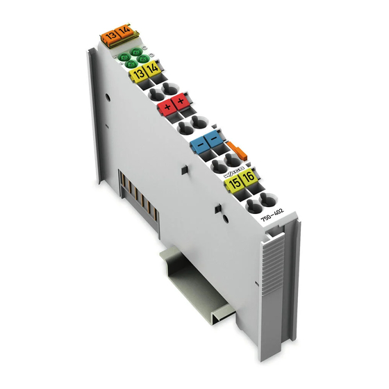
Pos : 22 /Serie 750 ( WAGO-I/O-SYST EM)/Ger ätebesc hrei bung/Ansic ht/Digitalei ngangs klemmen/Ansic ht 750- 0402 @ 9\mod_1295861125135_21.doc x @ 68661 @ @ 1 Figure 1: View Pos : 23 /Serie 750 ( WAGO-I/O-SYST EM)/Ger ätebesc hrei bung/Ansic ht/Ansic ht C ageCl amp® _Leg ende mit LED @ 15\mod_1370867188922_21.doc x @ 122225 @ @ 1 Table 1: Caption acc. to figure “View”... -
Page 16: Connectors
Pos : 27.3 /Serie 750 (WAGO-I/O-SYST EM)/Wic htige Erläuterungen/Sicherheits- und sonstig e Hinweis e/Achtung/Achtung: ESD - Auf g ute Erdung der U mgebung ac hten! @ 7\mod_1266318538667_21.doc x @ 50708 @ @ 1 Ensure that the environment is well grounded! The modules are equipped with electronic components that may be destroyed by electrostatic discharge. -
Page 17: Power Jumper Contacts/Field Supply
Pos : 30.3 /Serie 750 (WAGO-I/O-SYST EM)/Ger ätebesc hrei bung/Ansc hl üsse/Leistungs kontakte 2 LK (Mess er/Leis tungs kontakte 2 LK (Messer /Feder) - Abbil dung (ei nfac he Brei te) @ 15\mod_1367500700037_21.doc x @ 118396 @ @ 1 Figure 3: Power jumper contacts Pos : 30.4 /Serie 750 (WAGO-I/O-SYST EM)/Ger ätebesc hrei bung/Ansc hl üsse/Leistungs kontakte 2 LK (Mess er/Leis tungs kontakte 2 LK (Messer /Feder) - Legende @ 15\mod_1371721352500_21.doc x @ 123710 @ @ 1... -
Page 18: Cage Clamp
Pos : 34 /Serie 750 ( WAGO-I/O-SYST EM)/Wic htige Erläuterungen/Sicherheits- und sonstig e Hinweis e/Hi nweis /Hinweis: D I Potenti al ver vi elfäl tigungs modul e für Sensor vers orgung einsetzen @ 3\mod_1233762069125_21.doc x @ 27105 @ @ 1... -
Page 19: Display Elements
Display Elements Pos : 37 /Serie 750 ( WAGO-I/O-SYST EM)/Ger ätebesc hrei bung/Anz eigeelemente/Digitalei ngangs klemmen/Anz eigeel emente 750- 04xx 4 DI (Agn, Bg n, Cg n, Dg n) @ 9\mod_1291641003036_21.doc x @ 67080 @ @ 1 Figure 5: Display elements Table 6: Caption acc. -
Page 20: Schematic Diagram
Pos : 39 /All e Seri en (Allgemei ne Module)/Ü berschriften für alle Serien/Gerätebesc hreibung/Sc hematisches Sc haltbil d - Ü bersc hrift 2 @ 4\mod_1240984441312_21.doc x @ 31967 @ 2 @ 1 Schematic Diagram Pos : 40 /Serie 750 ( WAGO-I/O-SYST EM)/Ger ätebesc hrei bung/Schematisc he Sc haltbil der/Digitalei ngangs klemmen/Sc hematis ches Sc hal tbild 750-0402 @ 9\mod_1295863706202_21.doc x @ 68711 @ @ 1 Figure 6: Schematic diagram Pos : 41 /D okumentation allgemei n/Glieder ungs elemente/---Seitenwechs el--- @ 3\mod_1221108045078_0.doc x @ 21810 @ @ 1... -
Page 21: Technical Data
Pos : 42 /All e Seri en (Allgemei ne Module)/Ü berschriften für alle Serien/Gerätebesc hreibung/Technisc he Daten - Ü berschrift 2 @ 3\mod_1232967587687_21.doc x @ 26924 @ 2 @ 1 Technical Data Pos : 43 /Serie 750 ( WAGO-I/O-SYST EM)/Ger ätebesc hrei bung/T echnisc he Daten/Digitalei ngangs klemmen/Tec hnische D aten 750-0402 @ 9\mod_1295863611535_21.doc x @ 68707 @ 3333 @ 1 3.5.1 Device data Table 7: Technical data –... -
Page 22: Connection Type
Pos : 46 /Serie 750 ( WAGO-I/O-SYST EM)/Ger ätebesc hrei bung/T echnisc he Daten/T ec hnische D aten Kli matisc he U mwel tbedi ngungen m. er w. Tempber eich; 0...55°C /-20...+60°C/- 25...+ 85°C @ 5\mod_1247658089120_21.doc... -
Page 23: Approvals
Pos : 50 /Serie 750 ( WAGO-I/O-SYST EM)/Ger ätebesc hrei bung/Z ulass ungen/Allgemei n/Z ulass ungen Bus kl emme 750- xxxx Allgemein, Standardversi on und all e Vari anten - Einl eitung @ 3\mod_1233911570312_21.doc x @ 27390 @ @ 1... - Page 24 750-402 4DI 24V DC 3.0ms Pos : 57 /Serie 750 ( WAGO-I/O-SYST EM)/Ger ätebesc hrei bung/Z ulass ungen/Schiff/Z ulas sungen Bus klemme 750- xxxx Sc hiff, nur aufgelis tete Varianten - Ei nleitung @ 14\mod_1364210936228_21.doc x @ 115844 @ @ 1...
-
Page 25: Standards And Guidelines
Pos : 62 /Serie 750 ( WAGO-I/O-SYST EM)/Ger ätebesc hrei bung/N ormen und Ric htlini en/EM V-Nor men Bus kl emme 750- xxxx, Standardversi on und all e Varianten - Einl eitung @ 6\mod_1263981980650_21.doc x @ 48120 @ @ 1... -
Page 26: Process Image
Pos : 68 /All e Seri en (Allgemei ne Module)/Ü berschriften für alle Serien/Pr oz ess abbild - Übersc hrift 1 @ 4\mod_1240983067828_21.doc x @ 31942 @ 11 @ 1 Process Image Pos : 69 /Serie 750 ( WAGO-I/O-SYST EM)/Proz ess abbild Kl emmenbus /Digitalei ngangs klemmen/Pr oz ess abbild 750- x4xx 04 D I @ 4\mod_1236259579218_21.doc x @ 28028 @ @ 1 Table 12: Input bits... -
Page 27: Mounting
Pos : 72.2 /Serie 750 (WAGO-I/O-SYST EM)/Wic htige Erläuterungen/Sicherheits- und sonstig e Hinweis e/Vorsic ht/Vorsicht: Verl etz ungsgefahr durc h s charfkantige M ess er kontakte! @ 6\mod_1256193279401_21.doc x @ 43414 @ @ 1 Risk of injury due to sharp-edged male contacts! The male contacts are sharp-edged. -
Page 28: Inserting And Removing Devices
WAGO-I/O-SYSTEM 750 750-402 4DI 24V DC 3.0ms Pos : 72.6 /Serie 750 (WAGO-I/O-SYST EM)/M ontieren/D emontieren/Geräte einfüg en und entfer nen - Ü berschrift 2 @ 3\mod_1231768483250_21.doc x @ 25950 @ 22 @ 1 Inserting and Removing Devices Pos : 72.7 /All e Seri en ( Allgemei ne Module)/Wic htige Erläuterungen/Sicherheits- und sons tige Hi nweis e/Ac htung/Achtung: Arbeiten an Ger äten nur s pannungsfr ei durc hführ en! @ 6\mod_1256193963573_21.doc x @ 43426 @ @ 1 Perform work on devices only if the system is de-energized! Working on devices when the system is energized can damage the devices. -
Page 29: Removing The I/O Module
WAGO-I/O-SYSTEM 750 Mounting 750-402 4DI 24V DC 3.0ms Pos : 72.10 /Serie 750 ( WAGO-I/O-SYST EM)/Monti eren/D emonti eren/Bus kl emme entfer nen @ 4\mod_1239169375203_21.doc x @ 30334 @ 3 @ 1 5.2.2 Removing the I/O Module Remove the I/O module from the assembly by pulling the release tab. -
Page 30: Connect Devices
Pos : 74 /All e Seri en (Allgemei ne Module)/Ü berschriften für alle Serien/Ansc hließ en/Ger äte ansc hließen - Ü bers chrift 1 @ 3\mod_1234172889468_21.doc x @ 27460 @ 11 @ 1 Connect Devices Pos : 75 /Serie 750 ( WAGO-I/O-SYST EM)/Ans chli eßen/Leiter an C AGE C LAM P ans chli eßen - Ü berschrift 2 und T ext @ 3\mod_1225448660171_21.doc x @ 24928 @ 2 @ 1 ®... -
Page 31: Connection Examples
Pos : 77 /All e Seri en (Allgemei ne Module)/Ü berschriften für alle Serien/Ansc hließ en/Ans chl uss beis piel e - Ü berschrift 2 @ 4\mod_1240996036328_21.doc x @ 32010 @ 22 @ 1 Connection Examples Pos : 78 /Serie 750 ( WAGO-I/O-SYST EM)/Ans chli eßen/Anschl uss beispi ele/Digitalei ngangs klemmen/Ansc hlus sbeispi ele 750-04xx_4D I_2L_3L @ 11\mod_1322554789647_21.doc x @ 84038 @ 33 @ 1 6.2.1 2-Conductor Connection Figure 11: Connecting diagrams –... -
Page 32: Use In Hazardous Environments
Use in Hazardous Environments Pos : 80.2 /Serie 750 (WAGO-I/O-SYST EM)/Eins atz in Ex- Ber eichen/Ei ns atz ber eich Serie 750 @ 3\mod_1234272230203_21.doc x @ 27500 @ @ 1 The WAGO-I/O-SYSTEM 750 (electrical equipment) is designed for use in Zone 2 hazardous areas. -
Page 33: Marking Configuration Examples
Marking for Europe according to ATEX and IEC-Ex Pos : 80.6 /Serie 750 (WAGO-I/O-SYST EM)/Eins atz in Ex- Ber eichen/Beis piel bedruc kung der ATEX- und IEC- Ex-zug elass enen Bus klemmen gemäß C ENELEC und IEC_2013 @ 14\mod_1360569228625_21.doc x @ 111294 @ @ 1 Figure 13: Side marking example for approved I/O modules according to ATEX and IECEx Figure 14: Printing Text detail –... -
Page 34: Table 13: Description Of Marking Example For Approved I/O Modules According To Atex And Iecex
Use in Hazardous Environments WAGO-I/O-SYSTEM 750 750-402 4DI 24V DC 3.0ms Table 13: Description of marking example for approved I/O modules according to ATEX and IECEx Printing on Text Description TÜV 07 ATEX 554086 X Approving authority and certificate numbers IECEx TUN 09.0001 X... -
Page 35: Figure 15: Side Marking Example For Approved Ex I I/O Modules According To Atex And Iecex
750-402 4DI 24V DC 3.0ms Pos : 80.8 /Serie 750 (WAGO-I/O-SYST EM)/Eins atz in Ex- Ber eichen/Beis piel bedruc kung der Ex-i- und IEC-Ex-i-zug elas senen Bus klemmen gemäß C ENELEC und IEC _2013 @ 14\mod_1360569320118_21.doc x @ 111298 @ @ 1 Figure 15: Side marking example for approved Ex i I/O modules according to ATEX and IECEx. -
Page 36: Table 14: Description Of Marking Example For Approved Ex I I/O Modules According To Atex And Iecex
Use in Hazardous Environments WAGO-I/O-SYSTEM 750 750-402 4DI 24V DC 3.0ms Table 14: Description of marking example for approved Ex i I/O modules according to ATEX and IECEx Inscription text Description TÜV 07 ATEX 554086 X Approving authority and certificate numbers IECEx TUN 09.0001X... - Page 37 WAGO-I/O-SYSTEM 750 Use in Hazardous Environments 750-402 4DI 24V DC 3.0ms Table 14: Description of marking example for approved Ex i I/O modules according to ATEX and IECEx Gases Equipment group: All except mining 3(1)G Category 3 (Zone 2) equipment containing a safety...
-
Page 38: Marking For America According To Nec 500
750-402 4DI 24V DC 3.0ms Pos : 80.10 /Serie 750 ( WAGO-I/O-SYST EM)/Ei ns atz i n Ex-Bereic hen/Kennz eichnung für Ameri ka gemäß N EC 500 - Übersc hrift 3 @ 3\mod_1224158423187_21.doc x @ 24188 @ 3 @ 1 7.1.2... -
Page 39: Installation Regulations
WAGO-I/O-SYSTEM 750 Use in Hazardous Environments 750-402 4DI 24V DC 3.0ms Pos : 80.13 /Alle Serien (Allgemeine M odul e)/Ei ns atz i n Ex-Bereic hen/Errichtungsbes timmungen @ 3\mod_1232453624234_21.doc x @ 26370 @ 2 @ 1 Installation Regulations Pos : 80.14 /Alle Serien (Allgemeine M odul e)/Ei ns atz i n Ex-Bereic hen/Errichtungsbes timmungen Ei nleitung_2013 @ 14\mod_1360582328318_21.doc x @ 111371 @ @ 1... -
Page 40: Special Conditions For Safe Use (Atex Certificate Tüv 07 Atex 554086 X)
Pos : 80.16 /Serie 750 ( WAGO-I/O-SYST EM)/Ei ns atz i n Ex-Bereic hen/Besonder e Beding ung en für den sic her en Ex- Betrieb gem. AT EX-Z ertifi kat TÜV 07 ATEX 554086_X_2013_2 @ 15\mod_1368620071975_21.doc... -
Page 41: Special Conditions For Safe Use (Atex Certificate Tüv 12 Atex 106032 X)
Pos : 80.18 /Serie 750 ( WAGO-I/O-SYST EM)/Ei ns atz i n Ex-Bereic hen/Besonder e Beding ung en für den sic her en Ex- Betrieb gem. AT EX-Z ertifi kat TÜV 12 ATEX 106032x_2013_2 @ 15\mod_1368620479454_21.doc... -
Page 42: Special Conditions For Safe Use (Iec-Ex Certificate Tun 09.0001
Pos : 80.20 /Serie 750 ( WAGO-I/O-SYST EM)/Ei ns atz i n Ex-Bereic hen/Besonder e Beding ung en für den sic her en Ex- Betrieb gem. IEC-Ex-Z ertifi kat TUN 09.0001 X_2013_2 @ 15\mod_1368620660911_21.doc... -
Page 43: Special Conditions For Safe Use (Iec-Ex Certificate Iecex Tun 12.0039 X)
Pos : 80.22 /Serie 750 ( WAGO-I/O-SYST EM)/Ei ns atz i n Ex-Bereic hen/Besonder e Beding ung en für den sic her en Ex- Betrieb gem. IEC-Ex-Z ertifi kat TUN 12.0039 X_2013_2 @ 15\mod_1368620821493_21.doc... -
Page 44: Ansi/Isa 12.12.01
Use in Hazardous Environments WAGO-I/O-SYSTEM 750 750-402 4DI 24V DC 3.0ms Pos : 80.24 /Serie 750 ( WAGO-I/O-SYST EM)/Ei ns atz i n Ex-Bereic hen/Errichtungsbesti mmung en AN SI ISA 12.12.01_2013_2 @ 15\mod_1368620942842_21.doc x @ 119794 @ 3 @ 1 7.2.5 ANSI/ISA 12.12.01 “This equipment is suitable for use in Class I, Division 2, Groups A, B, C, D... -
Page 45: List Of Figures
WAGO-I/O-SYSTEM 750 List of Figures 750-402 4DI 24V DC 3.0ms Pos : 82 /D okumentation allgemei n/Verz eic hniss e/Abbil dungs verz eic hnis - Übersc hrift oG und Verz eichnis @ 3\mod_1219222916765_21.doc x @ 21080 @ @ 1 List of Figures Figure 1: View ....................... -
Page 46: List Of Tables
List of Tables WAGO-I/O-SYSTEM 750 750-402 4DI 24V DC 3.0ms Pos : 84 /D okumentation allgemei n/Verz eic hniss e/Tabell enverz eichnis - Übersc hrift oG und Verz eichnis @ 3\mod_1219222958703_21.doc x @ 21084 @ @ 1 List of Tables Table 1: Variants ..................... - Page 47 WAGO-I/O-SYSTEM 750 750-402 4DI 24V DC 3.0ms Pos : 86 /D okumentation allgemei n/Einband/Einband H andbuc h - Leers eite für ger ade Seitenz ahl @ 3\mod_1219230851078_0.doc x @ 21123 @ @ 1 Manual Version 1.1.0...
- Page 48 Pos : 87 /D okumentation allgemei n/Einband/Einband H andbuc h - R üc kseite @ 9\mod_1285229376516_21.doc x @ 64944 @ @ 1 WAGO Kontakttechnik GmbH & Co. KG Postfach 2880 • D-32385 Minden Hansastraße 27 • D-32423 Minden Phone: +49/5 71/8 87 – 0 Fax: +49/5 71/8 87 –...
Need help?
Do you have a question about the 750-402 and is the answer not in the manual?
Questions and answers