
Related Manuals for WAGO 752


Summary of Contents for WAGO 752
- Page 1 Fieldbus Dependent I/O Module INTERBUS Manual Technical Description, Installation and Configuration 752-122/000-002 Version 1.0.0...
- Page 2 • General Copyright ã 2001 by WAGO Kontakttechnik GmbH All rights reserved. WAGO Kontakttechnik GmbH Hansastraße 27 D-32423 Minden Ph.: +49 (0) 571/8 87 – 0 Fax: +49 (0) 571/8 87 – 1 69 E-mail: info@wago.com Web: http://www.wago.com Technical Support Ph.: +49 (0) 571/8 87 –...
-
Page 3: Table Of Contents
Table of Contents • iii Table of Contents 1 Important Explanations................1 Legal Basis .....................1 1.1.1 Copyright ..................1 1.1.2 Personnel Qualification..............1 1.1.3 Intended Use ..................1 Scope of Validity..................2 Symbols....................2 Abbreviations ..................3 2 System Description..................4 Base Module...................5 Electronic Module ..................6 3 Technical Data ....................7 4 Installation ....................11 Mechanical Installation ................11 4.1.1... - Page 4 Process Image and Diagnostic Status Bits ...........27 7.3.1 Process Image .................27 7.3.2 Diagnostic Status Bits ..............27 Fieldbus Controller Boards ..............28 Configuration Software ................28 Example of a Configuration with WAGO NETCON ......29 Configuration Example With CMD .............32 8 Accessories ....................34 9 Glossary.....................35 Fieldbus Dependent I/O Module INTERBUS...
-
Page 5: Important Explanations
WAGO Kontakttechnik GmbH. Please contact WAGO Kontakttechnik GmbH for any wishes in terms of a modified or a new hardware or software configuration. Fieldbus Dependent I/O Module... -
Page 6: Scope Of Validity
2 • Important Explanations 1.2 Scope of Validity This manual describes the fieldbus dependent I/O module of the WAGO-I/O-SYSTEM 752 for the INTERBUS. Components Article No. Electronic module 752-324 Base module 752-824 1.3 Symbols Warning Observe this information in all cases to protect the system from damage. -
Page 7: Abbreviations
Important Explanations • 3 1.4 Abbreviations Bus Active 1. Digital input 2. Data In (interface pin designation) 1. Digital output 2. Data Out (interface pin designation) Diagnostic status Input / Output Identifier, Identification Pin for plug recognition RBST Remote connected Remote disconnected Fieldbus Dependent I/O Module INTERBUS... -
Page 8: System Description
2 System Description The WAGO-I/O-SYSTEM 752 for INTERBUS is part of the compact series of WAGO field bus nodes for distributed automation. It has a fixed number of digital inputs (DI) and digital outputs (DO) and transmits the signals to a higher ranking control system via INTERBUS. -
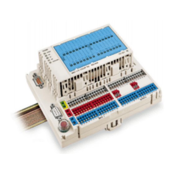
Page 9: Base Module
System Description • 5 2.1 Base Module The base module is the interface for all external wiring, including the fieldbus, power supply, and sensor/actuator connections. A multi-conductor connector links the external wiring to the plug-in electronic module. 10 11 12 13 14 15 16 10 11 12 13 14 15 16 17 18 19 20 21 22 23 24... -
Page 10: Electronic Module
Text can be added to the marking label using a permanent felt tip pen (order no. 210-110), or can be labeled by means of a plotter or a laser printer. The WAGO SCRIPT marking system has templates available for easy and profes- sional customization of marking labels. -
Page 11: Technical Data
Technical Data • 7 3 Technical Data INTERBUS System data Number of nodes 256 (depends on master) Number of I/O points 4096 inputs (depends on master) 4096 outputs (depends on master) Transmission medium certified Cu cable Max. length of fieldbus segment 400 m Baud rate 500 kbaud... - Page 12 8 • Technical Data Inputs Number of inputs Input in accordance with EN 61131-2, type 1 Wire connection for 3 conductors Signal voltage (0) DC –3 V ... +5 V Signal voltage (1) DC 15 V ... 30 V Time constant 5 ms Insulation none...
- Page 13 Technical Data • 9 Climatic Environmental Conditions Operating temperature 0 °C ... 55 °C Storage temperature -25 °C ... +70 °C Relative air humidity 10 ... 45 % , no dew formation Air pressure in operation 86 ... 106 hPa Maximum altitude max.
- Page 14 60 mm 8 mm PUSH PUSH INTERBUS READY OVERLOAD WAGO-I/O-SYSTEM 752 16DI/16DO 752-324 10 11 12 13 14 15 16 10 11 12 13 14 15 16 17 18 19 20 21 22 23 24 25 26 27 28 29 30 31 32...
-
Page 15: Installation
4.1 Mechanical Installation 4.1.1 Snapping on / Detaching the Base Module The WAGO-I/O-SYSTEM 752 is intended for mounting on a TS35 type car- rier rail. The base module snaps onto the carrier rail, as shown in Fig. 4-1. Fig. 4-1: Snapping the base module onto the carrier rail... -
Page 16: Insertion/Extraction Of The Electronic Module
Apply force at the positions marked “PUSH” in Fig. 4-3 when plugging in the electronic module. PUSH PUSH INTERBUS READY OVERLOAD WAGO-I/O-SYSTEM 752 16DI/16DO 752-324 Fig. 4-3: Plugging in the electronic module g1x2402x The electronic module is correctly inserted when all four latches have en- gaged. Latch... -
Page 17: Electrical Installation
Fig. 4-5: How to operate the CAGE CLAMP g1xxx10x The WAGO-I/O-SYSTEM 752 requires a 24 V DC supply. The sensors supply voltage is short circuit protected by means of the plug-in fuse F1 (TR 5 / 250 V / 6.3A T). -
Page 18: Connection Of The Module Supply Voltage
14 • Installation 10 11 12 13 14 15 16 10 11 12 13 14 15 16 17 18 19 20 21 22 23 24 25 26 27 28 29 30 31 32 17 18 25 26 33 34 35 36 37 38 39 40 41 42 43 44 45 46 47 48 33 34 35 36 37 38 39 40 41 42 43 44 45 46 47 48... -
Page 19: Connection Of The Input Signals
Installation • 15 4.2.3 Connection of the Input Signals The input signal connection group is identified by the imprint “INPUT” on the base module. Three terminals are available for each digital input. The termi- nals for one input are shown superimposed in Fig. 4.7. Vertical connection group for one channel Color Input... -
Page 20: Connection Of The Output Supply Voltage
16 • Installation 4.2.4 Connection of the Output Supply Voltage The supply voltage for the two output groups of 8 connections each can be provided either internally using the supply voltage for the module, or exter- nally from a separate power source. The base modules are provided with two sets of terminal blocks in the middle row of the output terminals. -
Page 21: Connection Of The Output Signals
If more than 6 Amps is applied to the common terminals, separate terminal blocks should be used. Connect all common connections to the terminal blocks, and then connect the 752 common to the terminal blocks. This row of terminal blocks will be wired back to the source common of the supply poten- tial. -
Page 22: Connection Of The Fieldbus Interface
18 • Installation 4.2.6 Connection of the Fieldbus Interface The WAGO-I/O-SYSTEM 752 for INTERBUS is provided with two 9 pole D-SUB plug connectors for interfacing to the INTERBUS network. Input interface: 9 pole D-Sub (male) GND1 Fig. 4-13: “Plug” connection assignment... -
Page 23: Cabling Of The Fieldbus Conductors
Installation • 19 4.2.7 Cabling of the Fieldbus Conductors Commercial 9 pole D-SUB plugs or sockets having a maximum housing width of 16 mm can be used as plug connectors. 9 pole D-SUB 9 pole D-SUB (male) (female) Color coding DO - DO Yellow DO DO... -
Page 24: Schematic Circuit Diagram
20 • Schematic Circuit Diagram 5 Schematic Circuit Diagram A basic representation of the input, output and supply circuitry are shown in Fig. 5-1. Sensor Supply of the Fieldbus supply output drivers connection (1 ... 16) Jumper 6,3 A 100nF 100nF 24 V 100nF... -
Page 25: Status Indicators
PUSH PUSH INTERBUS READY OVERLOAD WAGO-I/O-SYSTEM 752 16DI/16DO 752-324 Fig. 6-1: Status Indicators g1x2405x Fieldbus (INTERBUS) specific status indicators. Interference in the output circuit is displayed as a collective fault marked “OVERLOAD”. -
Page 26: Output Status Indicators
22 • Status Indicators 6.2 Output Status Indicators The output status LED’s display the actual state of each output. They will not be illuminated in the event of a short circuit at the output or a missing supply voltage to the output drivers. Output value of the higher ranking Fault controls... -
Page 27: Overload Status Indicator
Status Indicators • 23 6.4 Overload Status Indicator The LED designated “OVERLOAD”, when illuminated, indicates the pres- ence of an output fault. Possible output faults: • Short circuit of one or more outputs • Missing supply voltage to the output drivers •... -
Page 28: Interbus
24 • INTERBUS 7 INTERBUS 7.1 Overview INTERBUS is standardized in the EN 50 254 as a fieldbus. Its architecture is that of a data ring with a central bus master and bus slaves. The INTERBUS differentiates among several sub-variants, two fieldbus vari- ants of which should be mentioned for the decentralized periphery: •... -
Page 29: Description
• Fieldbus master : WAGO-I/O-SYSTEM 758, PC interface PCB INTERBUS-Master INTERBUS-Master of other manufacturers • Fieldbus equipment: WAGO-I/O-SYSTEM 750, modular I/O system, digital and analog I/O WAGO-I/O-SYSTEM 752, digital I/O modules WAGO-I/O-SYSTEM 755, digital I/O modules (IP67) Fieldbus Dependent I/O Module... -
Page 30: Module Properties
26 • INTERBUS The INTERBUS transmission log can be understood as a large shift register. Each slave, with its input and output data, bus position, and data width, is an integral part of this shift register. Input and output data are processed simulta- neously during a scan cycle. -
Page 31: Process Image And Diagnostic Status Bits
INTERBUS • 27 7.3 Process Image and Diagnostic Status Bits The process image is masked into the INTERBUS log word by word. Abbreviations Meaning Status of the digital input “x” Status of the digital output “x” Diagnostic status bit for the output group “x” Word 0 (in) 1. -
Page 32: Fieldbus Controller Boards
Before a PLC can communicate I/O data with a fieldbus device, the fieldbus controller board has to be configured for each field bus device on the network. To accomplish this, the WAGO-I/O-SYSTEM 758 fieldbus controller board is delivered with WAGO NETCON software for configuring and diagnosing fieldbus networks. -
Page 33: Example Of A Configuration With Wago Netcon
INTERBUS • 29 7.6 Example of a Configuration with WAGO NETCON The following example shows how to configure an I/O module using WAGO NETCON: 1. Start WAGO NETCON Fig. 7-2: WAGO NETCON icon p932x00x 2. Create a new project Create a new project and select INTERBUS as the fieldbus system. - Page 34 30 • INTERBUS 4. Add a slave remote bus device Add a remote bus device as a slave Menu path: Insert – remote bus equipment Fig. 7-5: Insert remote bus device p932x07e The devices on the INTERBUS network can be detected automatically by per- forming an “Automatic Network Scan”.
- Page 35 All input and output signals can be easily monitored and/or set using the inte- grated “I/O monitor”. Menu path: Online – I/O Monitor... With the debug mode activated, WAGO NETCON logs fault messages re- ceived from devices connected to the INTERBUS network. Menu path: Online – Start Debug Mode...
-
Page 36: Configuration Example With Cmd
32 • INTERBUS 7.7 Configuration Example With CMD The following example shows how to configure an I/O module using CMD. Reference the CMD manual for further description of this software. 1. Start CMD Fig. 7-10: CMD icon p932x08x 2. Create a new project Create a new project for your application. - Page 37 “Insert Device Description” dialog. An icon can be selected for the device by clicking the command button “Icon…”.. Further information Ask WAGO for the icons of the WAGO devices. They are available on floppy disc or via the WAGO INTERNET webside. http://www.wago.com Fig.
-
Page 38: Accessories
Pcs. per packing unit Symbols for CMD configuration software 750-913 (floppy disk) Marking label 16 DI/16DO 752-102 1 sheet (9 labels) Replacement fuse F1 (TR 5 / 250 V / 6.3A T) 752-180 Micro-fuse according to IEC 127-3 Note: Use UL-Recognized fuse only... -
Page 39: Glossary
Input / Output data I/O data Any fieldbus device from the WAGO-I/O-SYSTEM I/O module 752 series consisting of a base module and an elec- tronic module for the recording and output of digital signals. Input / output point, signal input or output... - Page 40 WAGO Kontakttechnik GmbH P.O. Box 2880 • D-32385 Minden Hansastraße 27 • D-32423 Minden Telephone: 05 71/8 87 – 0 Telefax: 05 71/8 87 – 1 69 E-Mail: info@wago.com Internet: http://www.wago.com...
Need help?
Do you have a question about the 752 and is the answer not in the manual?
Questions and answers