Table of Contents
Advertisement
Quick Links
®
Please Read
The GRAFIK Eye
QS control unit allows for control of both lights and window
®
treatments, without interfaces, using a single control unit. Features include
pushbutton scene recall, info screen that displays energy savings and status,
IR receiver, astronomic timeclock, contact closure input, and engravable backlit
buttons that are easy to find and operate.
Model Numbers: QSGRK-3PCE, QSGRK-4PCE, QSGRK-6PCE
QSGRM-3PCE, QSGRM-4PCE, QSGRM-6PCE
QSGR-3PCE, QSGR-4PCE, QSGR-6PCE
All units 230 V
50/60 Hz
QSGRK-3PCE
QSGRM-3PCE
QSGR-3PCE
1 500 W
Unit Capacity
(watts)
MLV
1 500 VA
1 200 W
Zone Capacity
40 - 500 W
(watts)
MLV
40 - 500 VA
40 - 400 W
See page 6 for IEC PELV ratings.
English
Español
Control Unit
LUTRON
QSGRK-4PCE
QSGRM-4PCE
QSGR-4PCE
2 000 W
2 000 VA
1 600 W
40 - 500 W
40 - 500 VA
40 - 400 W
Français
and Operation Guide
Contents
Wireless Mode . . . . . . . . . . . . . . . . . . . . . . . . .
Occupancy Sensor Setup . . . . . . . . . . . . . . . .
QSGRK-6PCE
QSGRM-6PCE
QSGR-6PCE
Troubleshooting . . . . . . . . . . . . . . . . . . . . . . .
2 300 W
Warranty . . . . . . . . . . . . . . . . . . . . . . . . . . . . .
Contact Information . . . . . . . . . . . . . . . . . . . .
2 300 VA
For additional features and advanced functions,
1 800 W
see the complete installation and operation guide at
40 - 500 W
www.lutron.com/qs
40 - 500 VA
40 - 400 W
Italiano
中文
Quick Installation
. . . . . . . . . . . . . . . . .
®
QS Control Unit
®
Overview of Line Voltage/Mains Wiring . . . . . . . . . 3
Line Voltage Wiring Details . . . . . . . . . . . . . . . . . . . 4
Overview of IEC PELV Wiring . . . . . . . . . . . . . . . . . 6
QS Link Control Wiring Details . . . . . . . . . . . . . . . . 7
Power Group Wiring Example . . . . . . . . . . . . . . . . 8
QS Control Unit . . . . . . . . . . . . .
®
Entering and Exiting Programming Mode . . . . . . 10
Navigating Menus in Programming Mode . . . . . . 10
Assigning Load Types . . . . . . . . . . . . . . . . . . . . . . 12
Assigning Non-Dim Load Type . . . . . . . . . . . . . . . 12
Setting Load Types . . . . . . . . . . . . . . . . . . . . . . . . 13
and Window Treatment Group Actions . . . . . . . 14
Scene Mode . . . . . . . . . . . . . . . . . . . . . . . . . . . . . 16
Configuring Occupancy Sensor Settings
(optional) . . . . . . . . . . . . . . . . . . . . . . . . . . . . . . . 17
®
Associating with a GRAFIK Eye
®
Wireless Control Unit . . . . . . . . . . . . . . . . . . . . . 18
Deutsch
2
9
11
15
QS
19
20
20
Advertisement
Table of Contents

Related Manuals for Lutron Electronics QSGRK-3PCE


Summary of Contents for Lutron Electronics QSGRK-3PCE
-
Page 1: Table Of Contents
Setting Load Types . . . . . . . . . . . . . . . . . . . . . . . . 13 Scene Setup Setting Zone Levels, Fade Rates, Model Numbers: QSGRK-3PCE, QSGRK-4PCE, QSGRK-6PCE and Window Treatment Group Actions . . . . . . . 14 QSGRM-3PCE, QSGRM-4PCE, QSGRM-6PCE Occupancy Sensor Setup . -
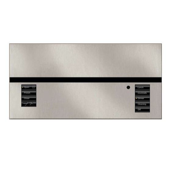
Page 2: Features And Functions Of The Grafik Eye
Features and Functions of the GRAFIK Eye QS Control Unit ® Hinged faceplate Info screen Zone numbers Displays status or programming functions Zone raise/lower buttons Master buttons Zone LEDs display current lighting zone levels Temporarily raise and lower lighting levels on unit Timeclock button Scene buttons Displays current... -
Page 3: Wiring The Grafik Eye
Wiring the GRAFIK Eye QS Control Unit: ® Overview of Line Voltage/Mains Wiring 1 2 3 4 5 6 L N Line Voltage/Mains 1 2 3 4 5 6 L N Cables and Load Wiring Terminal labels: L: Hot/Live N: Neutral : Ground 1-6: Dimmed/Switched line voltage outputs... -
Page 4: Line Voltage Wiring Details
Wiring the GRAFIK Eye QS Control Unit: ® Line Voltage Wiring Details • Use properly certified cable for all line voltage/mains cables. • Proper short-circuit and overload protection must be provided at the distribution panel. You can use up to a 20 A circuit breaker for your installation. • Install in accordance with all local and national electrical codes. -
Page 5: Qs Control Unit
Wiring the GRAFIK Eye QS Control Unit: ® Line Voltage Wiring Details (continued) Step 4: Connect line voltage and loads The recommended installation torque is 0.6 N∙m for line voltage/mains to control unit. connections and 0.6 N∙m for the earth/ • Strip 8 mm of insulation off the line ground connection. voltage/mains cables in the wallbox. Note: See the zone setup section for a list of compatible load types and instructions for programming the... -
Page 6: Overview Of Iec Pelv Wiring
Wiring the GRAFIK Eye QS Control Unit: ® Overview of IEC PELV Wiring IR Wiring 1.0 mm each terminal 1: IR DATA From external 2: IR COM IR connection (by others) 1 2 3 4 5 6 L N Contact Closure Input Wiring 1 2 3 4 5 6 L N 24 V 50 mA... -
Page 7: Qs Link Control Wiring Details
Wiring the GRAFIK Eye QS Control Unit: ® QS Link Control Wiring Details LUTRON LUTRON LUTRON T-Tap Wiring Example • System communication uses IEC PELV wiring. • Follow all local and national electrical codes when installing IEC PELV wiring with line voltage/mains GRAFIK Eye wiring. seeTouch ® ® control unit wallstation • Each terminal accepts up to two 1.0 mm wires. -
Page 8: Power Group Wiring Example
Wiring the GRAFIK Eye QS Control Unit: Power Group Wiring Example ® On the QS link, there are devices that supply power and devices that consume power. Each device has a specific number of Power Draw Units (PDUs) it either supplies or consumes. A Power Group consists of one device that supplies power and one or more devices that consume power; each Power Group may have only one power-supplying device. Refer to the QS Link Power Draw Units specification submittal (Lutron PN 369405) for more information concerning PDUs. -
Page 9: Completing Installation Of The Grafik Eye
Completing Installation of the GRAFIK Eye QS Control Unit ® 200 mm 1. Mount the control unit in the wallbox as shown using the four screws pro vid ed. Note: Follow all local and national electrical codes when installing IEC 87 mm PELV wiring with line voltage/mains 95 mm... -
Page 10: Programming Mode
Programming Mode Entering and Exiting Programming Mode Main menu Entering programming mode: Press and hold the top and bottom scene Timeclock Master buttons buttons simultaneously for 3 seconds. The Scene setup LEDs in the scene buttons will scroll from OK button top to bottom, confirming that you are in programming mode, and the info screen will Timeclock (back) button... -
Page 11: Wireless Mode
Wireless Mode Many models of the GRAFIK Eye QS control unit support wireless communication with ® other Lutron products. This feature allows for easy integration of wireless sensors, ® Master keypads, remotes, and window treatments for single-room wireless applications. buttons Units supporting wireless communication are labeled “GRAFIK Eye QS Wireless”... -
Page 12: Zone Setup
Zone Setup Assigning Load Types Master buttons Main menu 1. Enter programming mode. OK button 2. Use the Master buttons to highlight CCI Setup “Zone setup” and press the Zone setup OK button to accept. 3. Use the Master buttons to highlight Use the “Load type”. -
Page 13: Setting Load Types
Zone Setup (continued) Load Type Notes Setting Load Types • All electronic low-voltage (ELV) lighting used with an Direct control via Control via interface must be rated for reverse GRAFIK Eye power module or ® phase control dimming. Before control unit interface installing an ELV light source, Power verify with the manufacturer that... -
Page 14: Scene Setup
Scene Setup Setting Zone Levels, Fade Rates, and Window Treatment (Shade) Group Actions Master 1. Enter programming mode. Main menu buttons 2. Use the Master buttons to highlight “Scene setup” and press Timeclock the OK button to accept. button Scene setup 3. -
Page 15: Occupancy Sensor Setup
Occupancy Sensor Setup Associating wireless occupancy sensors and GRAFIK Eye QS Wireless control units ® (for wireless enabled units only): 1. Make sure the wireless mode of the GRAFIK Eye QS control Main menu ® Master unit is “Enabled”. buttons Zone Setup 2. -
Page 16: Scene Mode
Occupancy Sensor Setup Scene Mode This step allows you to assign up to four occupancy sensors to the GRAFIK Eye Master ® buttons control unit. Selecting Sensors Occ Sensor button 1. If not already done, associate occupancy sensors and set to Setup “Scene Mode”. -
Page 17: (Optional)
Occupancy Sensor Setup Configuring Occupancy Sensor Settings (optional) Occupancy Sensor Settings Master Main menu buttons Note: These settings affect all sensors assigned to the Zone Setup GRAFIK Eye QS control unit. ® button Sensor Setup Grace Period: If the GRAFIK Eye QS control unit is ®... -
Page 18: Pico
Pico Wireless Control Setup ® Associating the Pico wireless control with a GRAFIK Eye QS Wireless control unit: ® ® (for wireless enabled GRAFIK Eye QS control units only) ® Make sure the wireless mode of the GRAFIK Eye QS control unit is Pico ®... -
Page 19: Troubleshooting
Troubleshooting Symptom Possible Causes Solution Unit does not power up Circuit Breaker is off Switch circuit breaker on Unit does not control loads Miswire Verify wiring to unit and loads Circuit breaker is tripping System short circuited Find and correct shorts System overload Verify zone/unit loading is within ratings (see Zone Setup section) Zone control does not work... - Page 20 ANY AUTHORITY TO BIND LUTRON TO ANY AFFIRMATION, Savr and Energi Savr Node are trademarks of Lutron Electron ics Co., Inc. REPRESENTATION OR WARRANTY CONCERNING THE UNIT. © 2012 Lutron Electronics Co., Inc. Southern China: 10.800.120.1536 UNLESS AN AFFIRMATION, REPRESENTATION OR WARRANTY Hong Kong: 800.901.849...
Need help?
Do you have a question about the QSGRK-3PCE and is the answer not in the manual?
Questions and answers