Lutron Electronics GRAFIK Eye QS Quick Installation And Operation Manual
With dali control unit
Hide thumbs
Also See for GRAFIK Eye QS:
- Quick installation and operation manual (72 pages) ,
- Installation and operation manual (65 pages)
Table of Contents
Advertisement
Quick Links
GRAFIK Eye QS with DALI
Please Read
The GRAFIK Eye QS with DALI
of both lights and window treatments, without interfaces, using
a single control unit. Features include pushbutton scene recall,
info screen that displays energy savings and status, IR receiver,
astronomic timeclock, contact closure input, and engravable
backlit buttons that are easy to find and operate. The built-in
DALI
bus link can control up to 64 DALI
®
Model Numbers: QSGRK-6D, QSGRK-8D, QSGRK-16D
QSGR-6D, QSGR-8D, QSGR-16D
QSGRM-6D, QSGRM-8D, QSGRM-16D
Ratings:
230 V~ 50/60 Hz 100 mA
Output:
IEC PELV supply: 24 V- 150 mA
DALI
Link: 18 V- 250 mA
®
English
Español
®
LUTRON
control unit allows for control
®
devices.
®
Français
Control Unit
Quick Installation and
Operation Guide
Contents
Control Unit . . . . . . . . . . . . . . . . . . . . . . . . . . . . . . . . 2
®
Line Voltage Wiring Details . . . . . . . . . . . . . . . . . . . . . . . . . . . 4
Bus Wiring Details . . . . . . . . . . . . . . . . . . . . . . . . . . . . 5
®
Overview of IEC PELV Wiring . . . . . . . . . . . . . . . . . . . . . . . . . . 6
QS Link Control Wiring Details . . . . . . . . . . . . . . . . . . . . . . . . . 7
Power Group Wiring Example . . . . . . . . . . . . . . . . . . . . . . . . . . 8
Completing Installation . . . . . . . . . . . . . . . . . . . . . . . . . . . . . . 9
Entering and Exiting Programming Mode . . . . . . . . . . . . . . . . . . . 10
Navigating Menus in Programming Mode . . . . . . . . . . . . . . . . . . . 10
Wireless Mode . . . . . . . . . . . . . . . . . . . . . . . . . . . . . . . . . 11
Assigning Load Types . . . . . . . . . . . . . . . . . . . . . . . . . . . . . 12
Assigning Non-Dim Load Type . . . . . . . . . . . . . . . . . . . . . . . . 12
Group Actions . . . . . . . . . . . . . . . . . . . . . . . . . . . . . . . . . 13
®
Building the System . . . . . . . . . . . . . . . . . . . . . . . . . . . . . . 14
Associating Wireless Occupancy Sensors . . . . . . . . . . . . . . . . . . . 16
Scene Mode . . . . . . . . . . . . . . . . . . . . . . . . . . . . . . . . . 17
Associating Wireless Daylight Sensors . . . . . . . . . . . . . . . . . . . . 18
Zone Mode . . . . . . . . . . . . . . . . . . . . . . . . . . . . . . . . . . 19
Associating with a GRAFIK Eye QS Wireless Control Unit . . . . . . . . . . . 20
Troubleshooting . . . . . . . . . . . . . . . . . . . . . . . . . . . . . . . . . 21
Wireless Functions . . . . . . . . . . . . . . . . . . . . . . . . . . . . . . 22
®
Warranty . . . . . . . . . . . . . . . . . . . . . . . . . . . . . . . . . . . . . 24
Contact Information . . . . . . . . . . . . . . . . . . . . . . . . . . . . . . 24
For additional features and advanced functions, see the complete installation and
operation guide at www.lutron.com/qs
Italiano
®
Wiring . . . . . . . . . . . . . . . . 3
®
Device to a Zone . . . . . . . . . . . . . . . 15
®
Deutsch
Advertisement
Table of Contents

Related Manuals for Lutron Electronics GRAFIK Eye QS


Summary of Contents for Lutron Electronics GRAFIK Eye QS
-
Page 1: Table Of Contents
QSGR-6D, QSGR-8D, QSGR-16D Pico Wireless Control Setup Associating with a GRAFIK Eye QS Wireless Control Unit ... 20 QSGRM-6D, QSGRM-8D, QSGRM-16D Troubleshooting ....... . . 21 Wireless Functions . -
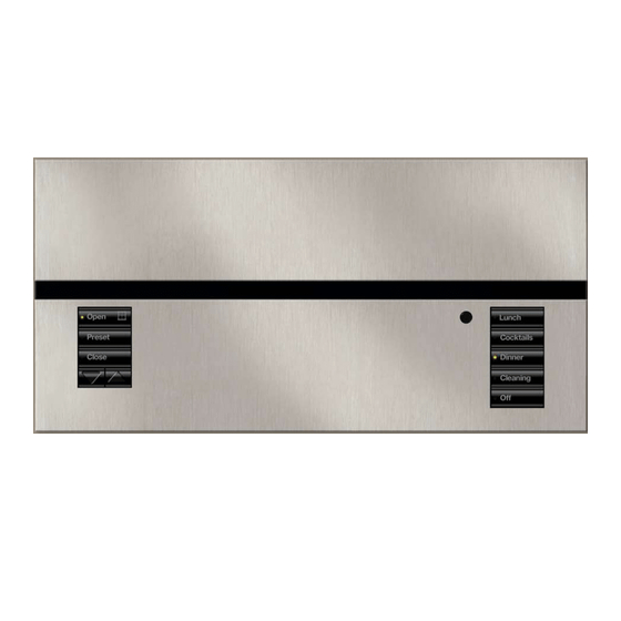
Page 2: Features And Functions Of The Grafik Eye Qs With Dali Control Unit
Features and Functions of the GRAFIK Eye QS with DALI Control Unit ® Page button Upper hinged faceplate Switches between displaying zones 1 to 8 and 9 to 16 on 16-zone unit Info screen Displays status or programming functions Master buttons... -
Page 3: Wiring The Grafik Eye Qs With Dali
Wiring the GRAFIK Eye QS with DALI Control Unit: ® Overview of Line Voltage/Mains and DALI Wiring ® Two D1 and two D2 connections are provided for ease of wiring, and to provide two connecting points; there is only one DALI link on the unit. -
Page 4: Line Voltage Wiring Details
Wiring the GRAFIK Eye QS with DALI Control Unit: ® Line Voltage Wiring Details • Use properly certified cable for all line voltage/mains cables. • Proper short-circuit and overload protection must be provided at the distribution panel. • Install in accordance with all local and national electrical codes. -
Page 5: Dali
® ® terminals. – Each DALI bus can have only 1 GRAFIK Eye QS with DALI ® ® • DALI bus wiring may be run in the same conduit as mains wiring. control unit connected to it. No additional DALI bus supplies ®... -
Page 6: Overview Of Iec Pelv Wiring
To control stations, 1: COM window treatments, 2: 24 V-* * Do not connect terminal 2 between any GRAFIK Eye QS control unit and any other power supply, or other 3: MUX including another GRAFIK Eye QS control unit. GRAFIK Eye QS... -
Page 7: Qs Link Control Wiring Details
System Limits The QS wired communication link is limited to 100 devices or Daisy-Chain Wiring Example 100 zones. The GRAFIK Eye QS control unit supplies 3 Power To DALI link 1 To DALI link 2 Draw Units (PDUs) on the QS link. Refer to the ®... -
Page 8: Power Group Wiring Example
Wiring the GRAFIK Eye QS with DALI Control Unit: ® Power Group Wiring Example On the QS link, some devices supply power and some devices consume power. Each device has a specific number of Power Draw Units (PDUs) that it either supplies or consumes. A Power Group consists of one device that supplies power and one or more devices that consume power;... -
Page 9: Completing Installation
Completing Installation of the GRAFIK Eye QS with DALI Control Unit ® 1. Mount the control unit in the wallbox as shown using the four screws provided. 200 mm Note: Follow all local and national electrical codes when installing IEC PELV/ Class 2 wiring with line ®... -
Page 10: Programming Mode
Pressing it repeatedly will eventually return you to the main menu, but will not exit programming mode. When the screen displays a Yes/No question, the Timeclock button is “No”. For additional information, see the complete installation and operation guide at www.lutron.com/qs GRAFIK Eye QS with DALI Control Unit Quick Installation and Operation Guide ®... -
Page 11: Wireless Mode
Lutron QS wireless (and compatible) products. • Ignore Programming (default): The GRAFIK Eye QS Wireless control unit operates normally but ignores any wireless devices in programming mode. Changing the wireless mode of the GRAFIK Eye QS Wireless control unit 1. -
Page 12: Zone Setup
5. The info screen will confirm that your load type Load Type has been saved. Set Zones 6. Exit programming mode. Saved For additional information, see the complete installation and operation guide at www.lutron.com/qs GRAFIK Eye QS with DALI Control Unit Quick Installation and Operation Guide ®... -
Page 13: Scene Setup
7. The info screen will confirm that your scene has been saved. Scene 1 8. Exit programming mode. Set Shade Groups Saved For additional information, see the complete installation and operation guide at www.lutron.com/qs GRAFIK Eye QS with DALI Control Unit Quick Installation and Operation Guide ®... -
Page 14: Dali
Erase Digital Load the GRAFIK Eye QS control unit.) Use the Zone 4 raise/lower buttons to verify that all devices are correctly Programming? addressed. If a device does not respond, repeat the “Build System” command and/or check the wiring. -
Page 15: Assigning/Unassigning A Dali
® • Refer to the Zone Setup section for instructions on changing load type. For additional information, see the complete installation and operation guide at www.lutron.com/qs GRAFIK Eye QS with DALI Control Unit Quick Installation and Operation Guide ®... -
Page 16: Occupancy Sensor Setup
6 seconds. The lens will start flashing and the Daylight info screen on the GRAFIK Eye QS Wireless control unit will display the sensor’s serial number. Add Wireless Sensors 6. Press the OK button on the GRAFIK Eye QS control unit. -
Page 17: Scene Mode
Unoccupied Scene Unassign Actions Saved No Action Scene Off Setup *Assigned* Sensor *x/y xxxxxxxx yyyy-yyyy For additional information, see the complete installation and operation guide at www.lutron.com/qs GRAFIK Eye QS with DALI Control Unit Quick Installation and Operation Guide ®... -
Page 18: Daylight Sensor Setup
The info screen on the GRAFIK Eye QS Daylight control unit will display the sensor’s serial number. 6. Press the OK button on the GRAFIK Eye QS control unit. A screen Add Wireless Sensors will confirm that the sensor has been assigned. (To disassociate... -
Page 19: Zone Mode
Daylight Sensor Setup (continued) Zone Mode This step allows you to assign sensors to zones on the GRAFIK Eye QS control unit. Each zone can be assigned to only one sensor, but sensors can be assigned to more than one zone. -
Page 20: Pico Wireless Control Setup
Wireless Control 4. On the Pico wireless control, press and hold the top and bottom buttons for 3 seconds until the LEDs on the GRAFIK Eye QS control unit stop flashing. Note: The wireless signal has a range of 9 m through standard Top/On button construction or 18 m line-of-sight. -
Page 21: Troubleshooting
QS device is not associated Place the QS device into programming mode, and hold the “Scene 1” button on the GRAFIK Eye QS control unit to associate the two devices QS device programming is incorrect Verify the functionality and programming on the QS devices... -
Page 22: Wireless Functions
Possible Causes Solution Cannot associate a wireless Unit does not support wireless functionality Verify the unit says “GRAFIK Eye QS Wireless” on the front label device to a unit Unit in incorrect wireless mode Change wireless mode to “Enabled” Maximum number of devices have been... -
Page 23: Dali ® Functions
System” or “Address all” command has been run DALI device at full D1 and D2 are not connected Check D1 and D2 connections on the back of the GRAFIK Eye QS with ® brightness cannot be DALI control unit ®... -
Page 24: Warranty
Directive 1999/5/EC. A copy of the DoC can Asia Customer Assistance NO LUTRON AGENT, EMPLOYEE OR REPRESENTATIVE HAS be obtained by writing to Lutron Electronics Co., Inc., 7200 Suter ANY AUTHORITY TO BIND LUTRON TO ANY AFFIRMATION, Northern China: 10.800.712.1536 Road, Coopersburg, PA 18036 USA.
Need help?
Do you have a question about the GRAFIK Eye QS and is the answer not in the manual?
Questions and answers