Braun Infusomat Space Service Manual
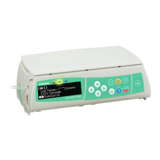
Infusion pump
Hide thumbs
Also See for Infusomat Space:
- Service manual (130 pages) ,
- Instructions for use manual (86 pages) ,
- Quick reference manual (18 pages)
Table of Contents
Advertisement
Advertisement
Chapters
Table of Contents


Need help?
Do you have a question about the Infusomat Space and is the answer not in the manual?
Questions and answers
When connecting the pump to the computer to download the library, the pump is not showing up on the left side of the screen. It worked for the other pumps, just not this one. I have rebooted computer, unplugged and plugged in cords several times but still not recognized. When I plug in the power the lights come on so I know it is connected. Thank you for your help! Karen