Table of Contents
Advertisement
Quick Links
CFO100
CFO200
MICRO-EPSILON Eltrotec GmbH
Manfred-Wörner-Straße 101 · 73037 Göppingen / Germany
Tel. +49 (0) 7161 / 98872-300 · Fax +49 (0) 7161 / 98872-303
eltrotec@micro-epsilon.com · www.micro-epsilon.com
Your local contact:
Operating Instructions
colorSENSOR
www.micro-epsilon.com/contact/worldwide/
CFO
Advertisement
Table of Contents

Related Manuals for MICRO-EPSILON colorSENSOR CFO


Summary of Contents for MICRO-EPSILON colorSENSOR CFO
- Page 1 Operating Instructions colorSENSOR CFO100 CFO200 MICRO-EPSILON Eltrotec GmbH Manfred-Wörner-Straße 101 · 73037 Göppingen / Germany Tel. +49 (0) 7161 / 98872-300 · Fax +49 (0) 7161 / 98872-303 eltrotec@micro-epsilon.com · www.micro-epsilon.com Your local contact: www.micro-epsilon.com/contact/worldwide/...
- Page 2 Sensor system for testing opaque, transparent and self-luminous objects MICRO-EPSILON Eltrotec GmbH Manfred-Wörner-Straße 101 73037 Göppingen / Deutschland Tel. +49 (0) 7161 / 98872-300 Fax +49 (0) 7161 / 98872-303 e-mail eltrotec@micro-epsilon.de www.micro-epsilon.de...
-
Page 3: Table Of Contents
System, Power and PLC (SYS) ....................29 4.3.2 Ethernet (ETH) ..........................30 4.3.3 Digital I/O (I/O) ..........................31 4.3.4 USB ............................... 32 4.3.5 Switching Input Circuit ......................... 33 4.3.6 Output Configuration ........................35 CFS Sensor ..............................37 Operation ..........................39 colorSENSOR CFO... - Page 4 Location Chart / Third Angle Projection ..............78 5.5.4.2 Timeline ........................79 5.5.5 Info Menu ............................82 System Parameterization via Web Interface (Menu Settings) ............... 83 5.6.1 Preliminary Remarks about the Settings ..................83 5.6.2 Parameters Overview ........................84 5.6.3 Detection Profile ........................... 85 colorSENSOR CFO...
- Page 5 5.6.8.4 Managing Settings ....................119 5.6.8.5 Reset Sensor ......................121 5.6.8.6 Update Firmware ....................... 122 Factory Reset ............................... 123 Notes for Operation ......................124 Cleaning ............................... 124 Disclaimer ..........................125 Service, Repair ........................126 Decommissioning, Disposal ....................127 colorSENSOR CFO...
- Page 6 Appendix Optional Accessories ......................128 Factory Settings ........................135 Interface Instructions ......................136 colorSENSOR CFO...
- Page 7 CFO Page 7...
- Page 8 CFO Page 8...
-
Page 9: Safety
Never fold the sensor (optical fiber) and do not bend it in tight radii. > Damage to or destruction of the sensor, partial failure of the measuring system Protect the ends of the sensor against contamination (use protective caps). > Failure of the test instrument colorSENSOR CFO Page 9... -
Page 10: Notes On Ce Marking
The EU Declaration of Conformity and the technical documentation are available to the responsible authori- ties according to the EU Directives. Intended Use - The colorSENSOR CFO is designed for use in an industrial environment. It is used for ƒ Relative color measurement or inspection ƒ Intensity measurement ƒ... -
Page 11: Proper Environment
The controller can be used in a wide temperature range and is stable. When all sockets are in use or plugged with a protective cap, the sensor can be used safely even under contaminated environmental conditions. colorSENSOR CFO Page 11... -
Page 12: Functional Principle, Technical Data
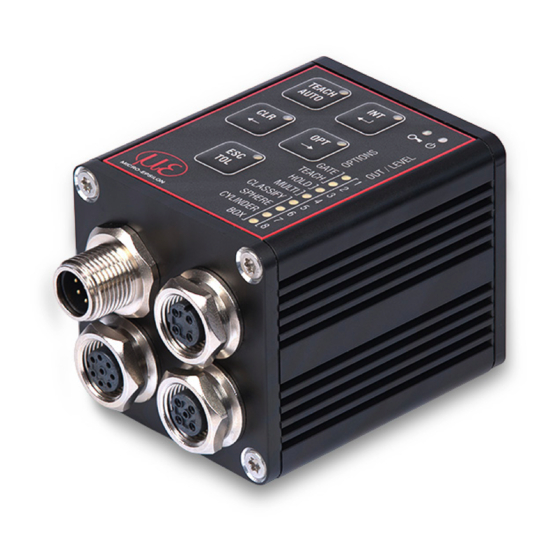
Functional Principle, Technical Data Short Description The colorSENSOR CFO is an optical controller for precise color recognition for industrial measurement, built into a sturdy aluminum housing. The controller is distinguished by high color accuracy, state-of-the-art inter- faces and intuitive operation. Sensors with optical fiber cables, which can be adapted for various measuring tasks, are connected to the controller. -
Page 13: Color Spaces
In the same manner, the color values and the recognized color are output as data protocol via the available interfaces as required. Color Spaces With the colorSENSOR CFO you can measure the following color spaces: XYZ, xyY, L*a*b*, L+u*v*, L*u‘v‘ For more details on color spaces, please refer to https://www.micro-epsilon.com/download/products/... - Page 14 In the Lab color space, a tolerance threshold of ∆E > 1 is frequently used for perceptible color differences. Influencing factors for setting color tolerance parameters: - Required accuracy for color recognition - Tolerance for reading variations. colorSENSOR CFO Page 14...
- Page 15 Cm to C1 ... C3 is the smallest, see Fig. Since the distance D3 between Cm and C3 is the smallest, the detected color is assigned to the color output of color C3 and output by the controller. colorSENSOR CFO Page 15...
-
Page 16: Functions
ƒ Switching outputs ƒ all interfaces mentioned above 2.5.2 Color Processing - Compilation of colors to form recognition groups - Variable color tolerance for each recognition group - Selection of various color spaces - Flexible averaging colorSENSOR CFO Page 16... -
Page 17: Technical Data Cfo100
Signal input (trigger, teach, delete, lock, calibration) Ethernet, Modbus RS232 (standard 9600 kBaud) Digital interface (TCP/RTU), PROFINET Ethernet EtherNet/IP , EtherCAT OUT0-OUT2 Push-Pull / NPN / PNP Switching output (color recognition, binary coding 6 color groups) colorSENSOR CFO Page 17... - Page 18 (R = 5%), measured with sensor CFS4-A20 at 1000 Hz and brightness adjustment with a white standard (R=95%) 2) Adjustable up to max. 115200 kBaud 3) Optional connection via interface module 4) Also compatible with previous series (FAR, FAD, FAL, FAZ and FAS) colorSENSOR CFO Page 18...
-
Page 19: Technical Data Cfo200
Signal input clear, lock, adjust) Ethernet, Modbus RS232 (standard 9600 kBaud) Digital interface (TCP/RTU), USB, PROFINET Ethernet, USB EtherNet/IP , EtherCAT OUT0-OUT2 Push-Pull / NPN / PNP Switching output (color recognition, binary coding 254 color groups) colorSENSOR CFO Page 19... - Page 20 (R = 5%), measured with sensor CFS4-A20° at 1000 Hz and brightness adjustment with a white standard (R=95%) 2) Adjustable up to max. 115200 kBaud 3) Also compatible with interface modules 4) Also compatible with previous series (FAR, FAD, FAL, FAZ and FAS) colorSENSOR CFO Page 20...
-
Page 21: Display Elements
- Key lock - Selected submenu The following settings are visible depending on the submenu selected: - LED intensity - Output coding - Tolerance - Tolerance model - Hold time - Trigger - Teach function (single or multiple) colorSENSOR CFO Page 21... -
Page 22: Delivery
Delivery Delivery Unpacking, Included in Delivery colorSENSOR CFO controller Assembly instruction Carefully remove the components of the test system from the packaging and ensure that the goods are forwarded in such a way that no damage can occur. Check the delivery for completeness and shipping damage immediately after unpacking. -
Page 23: Installation And Assembly
Installation and Mounting Ensure careful handling during installation and operation. The colorSENSOR CFO can be placed on a level surface or fastened with the dovetail on the rear of the controller. Position the controller so that the connections, controls and displays are not concealed. We recommend maintaining a clearance of 2 - 3 cm at the cooling ribs on the left and right sides. - Page 24 Do not allow the end surfaces of the sensor plug to hit against edges or surfaces. Reduced signal quality or 11.5 (.45) measuring device. 25.5 (1) 39.5 (1.56) Fig. 6 colorSENSOR CFO100/CFO200 dimensional drawing, dimensions in mm (inches) colorSENSOR CFO Page 24...
-
Page 25: Operating Elements
The following table provides an overview of the individual controls: Meaning Location TEACH Teach / AUTO Automatic modulation Illumination intensity Enter / Save Clear Arrow pointing left Select options Arrow pointing right Escape / quit without saving Color tolerances Fig. 7 Operating elements colorSENSOR CFO Page 25... -
Page 26: Controller Leds
Supply voltage connected Key lock active TEACH White Color teach menu AUTO White Menu for automatic illumination adjustment White Clear memory menu White Option selection menu White Tolerance adaptation menu Fig. 8 Controller LEDs - keys colorSENSOR CFO Page 26... - Page 27 SPHERE White Sphere (∆E) CYLINDER 7 White Cylinder (∆L, ∆ab) White Box (∆L, ∆a, ∆b) Fig. 9 Controller LEDs 1) The colorSENSOR CFO100 has only three switching outputs which correspond to the LEDs 1 … 3. colorSENSOR CFO Page 27...
- Page 28 The widely used and standardized M12 sockets allow the use of commercially available cables suitable for the special requirements of the respective operating environment. For example, cables are available which are oil-resistant or suitable for use with drag chains. colorSENSOR CFO Page 28...
-
Page 29: System, Power And Plc (Sys)
Ground connection 1) Conductor color OUT2 Switching output (NPN/PNP/PP) CAB-M12-8P-Bu-ge Fig. 12 SYS Power / PLC connector The three switching outputs are switchable push-pull outputs. The switching output logic level depends on the supply voltage V connected. colorSENSOR CFO Page 29... -
Page 30: Ethernet (Eth)
- with Ethernet network (PC) Connect the controller to the network using a shielded Ethernet cable (Cat5E) with a length of < 100 m. Micro-Epsilon recommends the optionally available cable CAB-M12-4P-St-ge ... RJ45-Eth with the PS2020 power supply unit, see A 1. -
Page 31: Digital I/O (I/O)
Connect the cable shield to the evaluation unit. All GND conductors are interconnected with one another and to the supply voltage ground. Use a shielded cable with a length < 30 m. Micro-Epsilon recommends the optionally available CAB-M12-8P-St-ge cable, see A Color... -
Page 32: Usb
Connect the cable shield to the evaluation unit. All GND conductors are interconnected with one another and to the supply voltage ground. Use a shielded cable with a length of max. 5 m. Micro-Epsilon recommends the optionally available CAB-M12-5P-St-ge cable, see A 1 Pin Color... -
Page 33: Switching Input Circuit
CFO Page 33... - Page 34 Comparator input with threshold at V /2 ±5 % Low Level < V /2 ±5 % High Level > V /2 ±5 % (max. 30 V) Switching levels always refer to V (10 V - 28 V) for all inputs. colorSENSOR CFO Page 34...
-
Page 35: Output Configuration
Not electrically separated, 24V logic NPN, PNP , PP , outputs cor- (HTL), low level = GND, respondingly programmed, high level = V = 100 mA Pink OUT1 detected color or color group directly or in binary code. OUT2 colorSENSOR CFO Page 35... - Page 36 (10 V - 28 V) for all outputs. High Level Low Level Output voltage Saturation voltage = 10 mA -0.3 V = 10 mA GND +0.2 V = 100 mA > -1.5 V = 10 mA GND < +1.5 V colorSENSOR CFO Page 36...
-
Page 37: Cfs Sensor
> Error-free recognition of colors no longer guaranteed > Erroneous measurements > Damage to sensor For this reason clean soiled end surfaces with pure alcohol and a clean, lint-free microfiber cloth. colorSENSOR CFO Page 37... - Page 38 Fiber breakage leads to a loss in the measuring sensitivity up to complete loss of the measuring signal. Replace the sensor only with the light source switched off to prevent dazzle. colorSENSOR CFO Page 38...
-
Page 39: Operation
Connect the controller to a power supply , see 4.3.1 Switch on the power supply. After switching on the controller, the green LED flashes and the red LED illuminates continuously as long as the controller is booting , see Fig. 21. colorSENSOR CFO Page 39... - Page 40 This means that after a brief voltage loss/power failure, the controller reboots independently and can reliably detect and evaluate the colors again within ms, and signal them accordingly at the switching output. colorSENSOR CFO Page 40...
-
Page 41: Configuration Of The Cfo Controller
Operation Configuration of the CFO Controller The colorSENSOR CFO can be configured using the network interface, the web interface, the serial interface and the keypad integrated into the housing. Due to the controller's range of functions, only the most impor- tant settings are possible via the keypad. -
Page 42: Key Functions
The key assignment changes to the longer actuation function after 2 seconds. From this time on the LED in the key illuminates continuously. The short actuation function is accomplished each time the key is pressed shortly. The function becomes effective when the key is released. colorSENSOR CFO Page 42... -
Page 43: Operation Using Membrane Keypad
The following instructions do not describe any specific procedure; they are simply a compilation of typical key actuations in the operating mode, see Fig. 23 and in the menu mode, see Fig. 24. Detailed descriptions of all actions, see 5.2 or, see 5.3.2 colorSENSOR CFO Page 43... - Page 44 (CLR/OPT) for less (Press) one of the menu menu than 2 sec to switch between colors, options, etc. within a menu. Menu mode Start action Press the TEACH/AUTO key for less than 2 sec. to trigger an event. colorSENSOR CFO Page 44...
-
Page 45: Intensity
Starting in the operating mode, first select the intensity menu by pressing (holding) the INT key for more than 2 sec. TEACH AUTO The intensity menu is then active. GATE TEACH HOLD MULTI CLASSIFY SPHERE CYLINDER colorSENSOR CFO Page 45... -
Page 46: Automatic Modulation
The modulation of the controller parameters should be set for the brightest color to be tested. GATE TEACH The controller should have reached operating temperature. Depending on the HOLD MULTI ambient conditions, this is the case after approx. 45 min. warm-up time. CLASSIFY SPHERE CYLINDER colorSENSOR CFO Page 46... - Page 47 HOLD MULTI CLASSIFY SPHERE CYLINDER After the completion of the automatic modulation, the INT LED is permanently lit. The output indicators visualize the achieved level of modulation. TEACH AUTO GATE TEACH HOLD MULTI CLASSIFY SPHERE CYLINDER colorSENSOR CFO Page 47...
-
Page 48: Manual Intensity Control
GATE TEACH HOLD MULTI CLASSIFY SPHERE CYLINDER After the new modulation is completed, the level of control achieved can be seen from the output LEDs. TEACH AUTO GATE TEACH HOLD MULTI CLASSIFY SPHERE CYLINDER colorSENSOR CFO Page 48... - Page 49 GATE TEACH To quit: HOLD MULTI CLASSIFY Press the ESC key for longer than 2 sec. SPHERE CYLINDER The results of the modulation are ignored. The display returns to the operating mode without saving the settings. colorSENSOR CFO Page 49...
-
Page 50: Color Management
- Slow flashing indicates that one color of the recognition group is being recog- nized (nearly continuous illumination 900/100 ms). All color groups or switching outputs to the color groups can be selected indi- vidually by pressing the arrow key colorSENSOR CFO Page 50... -
Page 51: Teaching Colors
Slow flashing indicates that this color is naturally detected at this moment, as long as the current target object has not moved. GATE TEACH HOLD Press the key for less than 2 sec. to switch to the next recognition MULTI CLASSIFY group. SPHERE CYLINDER colorSENSOR CFO Page 51... -
Page 52: Deleting Individual Color Groups
AUTO group to be deleted. Press the CLR key for longer than 2 sec. to delete the colors in the current recognition group. GATE TEACH HOLD Delete complete color table, see 5.3.5. MULTI CLASSIFY SPHERE CYLINDER colorSENSOR CFO Page 52... -
Page 53: Saving Or Quitting Upon Completion Of Teaching Process
When switching to a new recognition task, it is recommended to delete the color table completely. Press the CLR key for longer than 2 sec. to delete the color table completely. Output LEDs 1 - 8 are flashing. TEACH AUTO GATE TEACH HOLD MULTI CLASSIFY SPHERE CYLINDER colorSENSOR CFO Page 53... - Page 54 Press the ESC key for more than 2 sec. to cancel the deletion of all colors CYLINDER and return to the operating mode without saving. The output LEDs indi- cate either the recognition group or the output configuration for No color recognized, depending on the color detected. colorSENSOR CFO Page 54...
-
Page 55: Tolerance Setting
The tolerance is accessible in a color management submenu. All colors in one recognition group have the same tolerance. Press the TEACH key for longer than 2 sec. to access the (color) TEACH menu. TEACH AUTO GATE TEACH HOLD MULTI CLASSIFY SPHERE CYLINDER colorSENSOR CFO Page 55... - Page 56 The current color tolerance for the selected recognition group is displayed. Press the key for less than 2 sec. to increase the color tolerance. TEACH AUTO The changed color tolerance stage is displayed. GATE TEACH HOLD MULTI CLASSIFY SPHERE CYLINDER colorSENSOR CFO Page 56...
- Page 57 The changed color tolerance stage is displayed. TEACH AUTO Press the TEACH key for less than 2 sec. to return from the tolerance sub- menu to the color teach menu. GATE Teaching completed, see 5.3.4.3. TEACH HOLD MULTI CLASSIFY SPHERE CYLINDER colorSENSOR CFO Page 57...
-
Page 58: Options
(less than 2 sec.) to make the settings in the group. You can change the settings in an option group by shortly pressing TEACH (less than 2 sec.) to change or switch through the settings. colorSENSOR CFO Page 58... -
Page 59: In0 Switching Input Function Assignment
Triggered teach-in Triggered teach can be used to make run time changes to the color table with- of colors TEACH out direct human intervention. Here the input is configured as level trigger as level high. colorSENSOR CFO Page 59... - Page 60 IN0. HOLD MULTI CLASSIFY SPHERE CYLINDER Other functions of the trigger inputs can be configured via the REST API, described in the Interface Instruc- tions, see A 3, or via the web interface, see 5.5. colorSENSOR CFO Page 60...
-
Page 61: Hold Time
Press the TEACH key for less than 2 sec. to activate the hold time for all outputs. TEACH AUTO The activated hold time is signaled by the associated LED flashing. GATE TEACH HOLD MULTI CLASSIFY SPHERE CYLINDER colorSENSOR CFO Page 61... -
Page 62: Multi-Teach Mode
After reaching the maximum for the color memory, no further colors are learned. Press the key for less than 2 sec. to switch to the next option group. TEACH AUTO GATE TEACH HOLD MULTI CLASSIFY SPHERE CYLINDER colorSENSOR CFO Page 62... -
Page 63: Tolerance Mode
Changing the tolerance mode is useful if your application requires specific color tolerances, see 2.4. Press the key for less than 2 sec. to switch to the next option group. TEACH AUTO GATE TEACH HOLD MULTI CLASSIFY SPHERE CYLINDER colorSENSOR CFO Page 63... - Page 64 Press the TEACH key for less than 2 sec. again to switch to the next toler- GATE ance mode. TEACH HOLD MULTI CLASSIFY SPHERE CYLINDER The Box tolerance mode is reached. TEACH AUTO GATE TEACH HOLD MULTI CLASSIFY SPHERE CYLINDER colorSENSOR CFO Page 64...
-
Page 65: Conclusion Of Option Settings: Save Or Quit
If the key LED lights up red continuously, the keypad is locked. If the LED is off, the keyboard is enabled. Via the web page or REST API, described in the Interface Instructions, see A 3, the switching input can also be configured to lock or unlock the controller keypad. colorSENSOR CFO Page 65... -
Page 66: Configuration Via Ethernet
Using the sensorTOOL program, you can search for connected CFO series controllers on your PC via the available interfaces and establish a connection. The sensorTOOL program is available online at https://www.micro-epsilon.com/download/software/sensorTOOL.exe Start the sensorTOOL program. Set the Sensor group Color in the drop-down menus and the corresponding CFO type in Sensor type. colorSENSOR CFO Page 66... - Page 67 You need an HTML5-compatible web browser on a PC/notebook. Click on the button with the magni- Click the Open Website button. Select a desired sensor. fying glass icon. The program searches the available interfaces for connected colorSENSOR CFO controllers. colorSENSOR CFO Page 67...
-
Page 68: Access Via Ethernet (Connection Establishment)
1) This assumes that the LAN connection on the PC uses the following IP address, for example: 169.254.168.1. 2) Some Ethernet modules in the PC may cause long waiting times when establishing a connection. To avoid this, we recommend us- ing a Belkin Ethernet to USB 3.0 adapter colorSENSOR CFO Page 68... - Page 69 Start a web browser on your PC. To reach a CFO100 with the serial number “7454229522”, enter “CFO-7454229522” in the web browser address line. Interactive web pages for controller and peripherals settings now appear in the web browser. colorSENSOR CFO Page 69...
-
Page 70: Web Interface
Web Interface Launch the web interface of the color measuring system, see 5.4.2. Interactive web pages for programming the controller now appear in the web browser. Fig. 26 First interactive web site after calling the web interface colorSENSOR CFO Page 70... - Page 71 Measurement section, see 5.7. Parallel control via web browser and API commands is possible (REST API, described in Interface Instructions, see A 3), the last setting is valid and is saved automatically every 30 seconds. colorSENSOR CFO Page 71...
-
Page 72: Home Menu
System settings. You can choose German, English, Chinese, Japanese and Korean as web interface language. Fig. 27 Language selection The following symbols and functions are available in the Home, Settings and Measurement menus. Measurement is active Measurement stopped Stop measurement Start measurement Save measurement results colorSENSOR CFO Page 72... -
Page 73: Color Display
You can make settings for the color group in the Settings > Color group menu, see 5.6.4. In the Home view, the following windows are displayed on the left side including the settings you have se- Settings, see 5.6 lected under the menu. colorSENSOR CFO Page 73... -
Page 74: Settings Display
1 color group with a total of 6 colors System Settings Displays the settings you have chose in the Settings > Sys- tem settings menu. Example: Professional Logged user ... IPv4 Method and IP address ... IPv6 Method and MAC address colorSENSOR CFO Page 74... -
Page 75: Measurement Menu
If you allow the diagram display to run in a separate browser tab or window, it is not necessary to restart the display each time. The diagrams start automatically when the function is called. Fig. 29 Measurement menu colorSENSOR CFO Page 75... - Page 76 L a b View can be set individually, see Fig. 31, see Fig. Location dia- a-L, L-b, a-b gram Fields with gray background re- quire a selection. Fields with dark Val- border require entry of a value. colorSENSOR CFO Page 76...
- Page 77 Fig. 30 depending on the selected color space. For more details on color spaces, please refer to https://www.micro-epsilon.com/download/products/ dat--Basics-of-colorimetry--en.pdf. Fields with gray background re- quire a selection. Fields with dark Val- border require entry of a value. colorSENSOR CFO Page 77...
-
Page 78: Location Chart / Third Angle Projection
RGB cannot represent all real colors. However, since most display media are based on RGB technology, but the measuring system operates in the XYZ range, the colors displayed do not correspond to reality and can only be approximated (see also Basics of Colo- rimetry). Fig. 66 Measurement chart, location diagram colorSENSOR CFO Page 78... -
Page 79: Timeline
Now a measurement recording starts depending on the runtime when the diagram is activated/start. Via the time diagram, color changes can be recorded over a longer period of time (up to 50,000 measurements). If you need a longer recording, you can use the sensorTOOL program, see 5.4.1. Fig. 32 Measurement chart and timeline menu colorSENSOR CFO Page 79... - Page 80 The color values to be shown in the diagram can be defined with the selection, see Fig. 30, see Fig. It is always necessary to select at least one channel for display! colorSENSOR CFO Page 80...
- Page 81 If a color group is recognized, the corresponding group name is displayed. If a color group is recognized, the relative distance ∆E from the recognized color in the color table is displayed. When a color group is detected, the current output wiring is displayed. colorSENSOR CFO Page 81...
-
Page 82: Info Menu
Fig. 34 Info menu view In addition, you will find the interface logs for the respective programming interface (Ethernet / REST API) and the serial interface (RS232 / USB), described in the Interface Instructions, see A colorSENSOR CFO Page 82... -
Page 83: System Parameterization Via Web Interface (Menu Settings)
After programming, save all settings permanently in a parameter set, so that they will be available again the next time you switch on the controller, System settings > Manage settings > Export settings. The controller automatically saves the changes internally every 30 seconds. colorSENSOR CFO Page 83... -
Page 84: Parameters Overview
Operation 5.6.2 Parameters Overview You can set or change the following parameters in the colorSENSOR CFO, see Settings menu: Detection profile, see Manage detection profiles, Current 5.6.3 detection profile, Automatic modula- tion, White reference Color group, see 5.5.2 Distance model, Hold time Color table, see 5.6.5... -
Page 85: Detection Profile
Go to the menu Settings > Detection profile. Fig. 36 Detection profile window In the detection profile you can set and save the basic settings for the colorSENSOR CFO, such as color space, measurement frequency, automatic modulation and white reference. -
Page 86: Manage Detection Profiles
Up to 10 detection profiles can be stored and switched in the controller. Not only the settings but also the color table are stored in the detection profile, as they are interdependent and cannot be converted. colorSENSOR CFO Page 86... -
Page 87: Current Detection Profile
If possible, the hold time should not be longer than a Fields with dark Val- few seconds, otherwise changes in state will no longer border require be perceived. entry of a value. Fig. 38 Current detection profile Click the Apply button to apply all settings. colorSENSOR CFO Page 87... -
Page 88: Automatic Modulation
The modulation of the controller parameters should be set for the brightest color to be tested. The controller should have reached operating temperature; depending on the ambient conditions. This is the case after approx. 45 min. warm-up time. colorSENSOR CFO Page 88... - Page 89 During automatic modulation, the lightest color to be detected should be placed under the sensor. Fields with dark Val- border require 1) Numerical value for CFO100 between 0.01 ... 10,000, for CFO200 between 0.01 ... 30,000 entry of a value. colorSENSOR CFO Page 89...
-
Page 90: White Reference
You can reset the customized white Fields with dark Val- reference to factory settings. border require entry of a value. Click on Set new to perform a white reference. colorSENSOR CFO Page 90... - Page 91 The white balance can also be used to spread the signal thus improving the difference between light and dark. In this case the lightest color to be detected is defined as white (L = 100, a = 0, b = 0). colorSENSOR CFO Page 91...
-
Page 92: Color Group (Matcher)
Go to the Settings > Color group menu. Fig. 41 Color group Depending on the version, the colorSENSOR CFO controller can save up to 320 colors in up to 254 color groups in the internal color table and use them for color recognition. -
Page 93: Distance / Tolerance Space
Classification, quire a selection. Edge length (L) Value Sphere, Cylinder and Edge length (a) Value Box (cuboid) with Fields with dark Val- the respective range border require Edge length (b) Value entry of a value. settings. colorSENSOR CFO Page 93... -
Page 94: Hold Time
Fields with dark Val- If possible, the hold time should not be longer than a few seconds, otherwise state changes can no border require entry of a value. longer be perceived. colorSENSOR CFO Page 94... -
Page 95: Color Table
New colors can be taught and added to the corresponding color group memory. Individual colors, entire color groups or the entire color table can be deleted. The Add new color group button teaches the current color to the next free color group memory. Fig. 44 Color table window colorSENSOR CFO Page 95... - Page 96 Operation Fig. 45 Settings - Color table menu colorSENSOR CFO Page 96...
-
Page 97: Add Color Group
5.6.4 The new color group is always taught (binary coded) to the smallest free output combination. The output configuration and parameters can be changed under, see 5.6.5.2, yet. Fig. 46 Color display window colorSENSOR CFO Page 97... -
Page 98: Teaching And Editing Colors
Before creating a new color table, set the parameters for the color space and controller modulation, see Settings > Detection profile menu, see 5.5.3. If you subsequently change the controller modulation, all colors must be learned again. colorSENSOR CFO Page 98... - Page 99 Allows you to change and set the color group parameters for the selected color group. Deletes the entire color group including the stored individual colors. Deletes the selected individual color. Apply button saves the changes to this color group. Cancel button discards the changes to this color group. colorSENSOR CFO Page 99...
- Page 100 2.4. If the controller detects a color within the tolerance limits, it indicates the status on the left side of the window with a depiction of the current color. colorSENSOR CFO Page 100...
- Page 101 These can be manually adjusted in the edit mode of the group between 0 ... 50. The maximum name length is 64 characters and may consist of only alphanumerical characters (a-z, A-Z, 0-9, no foreign character attributes), spaces and the special characters +-#,.(). colorSENSOR CFO Page 101...
- Page 102 Classify / Sphere / Cylinder / Box Tolerance value ∆E Value 0.00...50.00 ∆L / ∆ab Value 0.00...50.00 ∆L / ∆a / ∆b Value 0.00...50.00 Fields with gray background re- quire a selection. Fields with dark Val- border require entry of a value. colorSENSOR CFO Page 102...
-
Page 103: Deleting Colors, Color Table
Via the button Delete color table (3), you remove all colors and color groups from the color table. You can delete the color groups, see 5.3.4.2 and color table, see 5.3.6, also via the key control or a trigger event, see 5.6.6. colorSENSOR CFO Page 103... -
Page 104: Trigger Input
- Automatic modulation for sensor LED - Rerecording white reference - Activating key lock Each trigger can be linked to one or several of the above activities, see also more differentiated list of func- tions, see Fig. colorSENSOR CFO Page 104... - Page 105 Operation Fig. 49 Trigger input window Fig. 50 Example: Level High - No function After selecting a trigger input, click the Apply button to activate the selected trigger event. colorSENSOR CFO Page 105...
- Page 106 With this setting, you can also select whether all previous colors in this group are Fields with dark Val- to be deleted beforehand or whether they are to be added. border require entry of a value. colorSENSOR CFO Page 106...
- Page 107 Fields with dark Falling edge Change of state between H (> V /2 ±5 %) to L (< V /2 ±5 %). During this change, the Val- border require stored function is executed. entry of a value. colorSENSOR CFO Page 107...
- Page 108 The measured value output can also be stopped using a command. Further functions of the trigger inputs can be configured via the REST API, described in the Interface Instruc- tions, see A 3, or via the web page. colorSENSOR CFO Page 108...
-
Page 109: Outputs
(L & a & b), the color is then considered to be recognized. If the color is not within the specified parameters, the output for Color not recognized becomes active. In the delivery state this is all outputs at high. colorSENSOR CFO Page 109... - Page 110 ) when color group is detected (activated) and to ground (GND) when not detected Number of out- Value puts Fields with gray background re- quire a selection. Fields with dark Val- border require entry of a value. colorSENSOR CFO Page 110...
-
Page 111: System Settings
System Settings Go to menu Settings > System settings. System settings such as Language selection, Switch user, Ethernet settings, Reset sen- sor and Update firmware are set under this menu item. Fig. 56 System settings window colorSENSOR CFO Page 111... -
Page 112: Select Language
Language when Browser Determines the language used when Fields with gray loading loading the web page. background re- English quire a selection. German Chinese Fields with dark Val- border require Japanese entry of a value. Korean colorSENSOR CFO Page 112... -
Page 113: Switch User
The controller works on the Professional level. After the controller has been configured, you should enable password protection. The standard password for the Professional level is 000. The password can be changed after the first logout and login, see Fig. colorSENSOR CFO Page 113... - Page 114 Operation Fig. 59 Change password A software update will not change the default password or a user-defined password. The Professional password is independent from Setup and is thus not loaded or stored with Setup. colorSENSOR CFO Page 114...
-
Page 115: Ethernet Settings
Here you can change the IPv4 settings of the controller. After changing the IP address, you may also have to adjust the address space of the PC you are using to re-establish a connection to the sensor. Fig. 60 Window Ethernet settings IPv4 colorSENSOR CFO Page 115... - Page 116 With DHCP it may be neces- sary to enable the controller Fields with dark Val- MAC address in the network. border require entry of a value. Go to the menu Settings > System settings > Ethernet settings IPv4. colorSENSOR CFO Page 116...
- Page 117 62, fe80::20c:12ff:fe02:10a5 (leading zeros within a block are omitted; consecutive 0000 are abbreviated by ::), means written out fe80:0000:0000:020c:12ff:fe02:10a5. Fig. 61 Window Ethernet settings IPv6 - Automatic Fig. 62 Window Ethernet settings IPv6 - Static method method colorSENSOR CFO Page 117...
- Page 118 The controller transfers the TCP/IP or UDP/IP packages at the Ethernet transfer rate of 10 MBit/s or 100 entry of a value. MBit/s, which is set automatically depending on the network or PC connected. colorSENSOR CFO Page 118...
-
Page 119: Managing Settings
However, it is recommended to save the data in an exter- nal parameter set to be able to reconstruct them in case of a system failure. To do this, select Manage settings > Export set- tings > Export. Fig. 63 Manage settings colorSENSOR CFO Page 119... - Page 120 Operation Managing set- Export settings Controller settings Exports all settings of tings colorSENSOR CFO to a file. Colors Ethernet settings Import settings Controller settings Imports settings from a file to the color- SENSOR CFO. Colors Ethernet settings Export: The file can be used to transfer settings from one colorSENSOR to another or to send to support in case of problems.
-
Page 121: Reset Sensor
Reset Sensor Go to the menu Settings > System settings > Reset sensor. Here you can reset the colorSENSOR CFO to the factory settings or restart it. Fig. 64 Reset sensor Clicking Factory defaults overwrites the currently used settings with the factory settings, including all changes related to the detection profile, color table, interface configuration. -
Page 122: Update Firmware
Update Firmware Go to the menu Settings > Systems settings > Update firmware. This function allows you to update the colorSENSOR CFO with the selected firmware file. Fig. 65 Update firmware Click the Browse button to select your firmware file. -
Page 123: Factory Reset
Key actuation is acknowl- edged by error flashing (3x100 / 300 ms). Indicators Output LEDs: Pulsating progress bar (indeterminate progress bar) Key LEDs: Not illuminated Power LED: Illuminated continuously Key-lock LED: Illuminated continuously colorSENSOR CFO Page 123... -
Page 124: Notes For Operation
This can be accomplished with an anti-static lens brush or by blowing off the lens with dehumidified, clean, oil-free compressed air. Wet Cleaning Use a clean, soft, lint-free cloth or lens cleaning paper and lens cleaner to clean the lens. Never use commercially available glass cleaner or other cleaning agents. colorSENSOR CFO Page 124... -
Page 125: Disclaimer
/ or technical modifications or alterations to the product. In the interest of further development, MICRO- EPSILON reserves the right to modify the design. In addition, the General Terms of Business of MICRO-EPSILON shall apply, which can be accessed under Le- gal details | Micro-Epsilon https://www.micro-epsilon.com/impressum/. For translations into other languages, the German version shall prevail. -
Page 126: Service, Repair
Service, Repair Service, Repair If the controller or the sensor are defective, please MICRO-EPSILON Eltrotec GmbH send in the affected parts for repair or replacement. Manfred-Wörner-Straße 101 If the cause of a fault cannot be clearly identified, 73037 Göppingen / Deutschland... -
Page 127: Decommissioning, Disposal
Here you can inform yourself about the respective national collection and return points. - Old devices can also be returned for disposal to MICRO-EPSILON at the address given in the imprint at https://www.micro-epsilon.de/impressum/. - We would like to point out that you are responsible for deleting the measurement-specific and personal data on the old devices to be disposed of. - Page 128 Ethernet cable CAB-M12-4P- Ethernet cable; 2 m long 11234735 St-ge;2m-PUR- Cat5e;RJ45-Eth CAB-M12-4P- Ethernet cable; 5 m long 11234736 St-ge;5m-PUR- Cat5e;RJ45-Eth CAB-M12-4P-St- Ethernet cable; 5 m long; 11234737 ge;5m-PUR-Cat5e- for use with drag chain D;RJ45-Eth colorSENSOR CFO Page 128...
- Page 129 USB cable USB cable CAB- USB cable; 2 m long 11234732 M12-5P-St-ge;2m- PUR;USB USB cable CAB- USB cable; 5 m long 11234733 M12-5P-St-ge;5m- PUR;USB CAB-M12-5P-St- USB cable; 5 m long; 11234734 ge;5m-PUR-D;USB for use with drag chain colorSENSOR CFO Page 129...
- Page 130 Anhang | Optional Accessories Name Photo Description Article number Power supply PS2020 Power supply for top-hat rail instal- 2420062 lation, input 230 VAC, output 24 VDC/2.5 A PS2031 Plug-in power pack 24V/24W/ 1A; 2420096 2m-PVC; Terminal-2P-BU-ge colorSENSOR CFO Page 130...
- Page 131 Anhang | Optional Accessories Name Photo Description Article number CFS Sensor (Color Fiber Sensor) CFS4-C20 Reflex sensor 10810568 Further sensors can be found in the catalog or are available on request. colorSENSOR CFO Page 131...
- Page 132 CFO100 or CFO200 or as replacement for colorSENSOR LT-1-LC-10 and LT-1-ST CFO DIN rail mount- Accessory for CFO mounting 11234762 ing kit adapter (Part No.: 11234713) for mounting on standard mounting rail (top hat rail TS35) colorSENSOR CFO Page 132...
- Page 133 (top hat rail TS35) Protective caps Protective cap M12 Protective cap for 11234789 for cable box covering open, unused connection sockets for IP65 protection Protective cap M18 Protective cap 37930128 for FA adapter avoids soiling of LED and receiver colorSENSOR CFO Page 133...
- Page 134 Anhang | Optional Accessories Name Photo Description Article number Additional information White standard White standard; 11234694 reflection 99 % 11234695 Vacuum feed-through Vacuum feed- 10811916 through C-mount lens C-mount lens 11293186 colorSENSOR CFO Page 134...
- Page 135 Default data, deletes all learned colors Measurement averaging Automatic depending on measurement frequency using max. 200 values Color space Color tolerance space Cylinder (∆L, ∆ab) Color tolerance stage 4 (∆L = 8.0; ∆ab = 4.0) Operating mode after system start Ethernet colorSENSOR CFO Page 135...
- Page 136 Anhang | Interface Instructions Interface Instructions The current Interface Instructions for the colorSENSOR CFO contains the interfaces: - REST API - RS232 or USB - Modbus The documentation is available at https://www.micro-epsilon.com/download/manuals/man--colorSENSOR-CFO-Interfaces-en.pdf colorSENSOR CFO Page 136...
- Page 138 MICRO-EPSILON Eltrotec GmbH Manfred-Wörner-Straße 101 · 73037 Göppingen / Germany Tel. +49 (0) 7161 / 98872-300 · Fax +49 (0) 7161 / 98872-303 X9751375-B012032HDR eltrotec@micro-epsilon.com · www.micro-epsilon.com MICRO-EPSILON Eltrotec Your local contact: www.micro-epsilon.com/contact/worldwide/...
Need help?
Do you have a question about the colorSENSOR CFO and is the answer not in the manual?
Questions and answers