
Subscribe to Our Youtube Channel
Related Manuals for MICRO-EPSILON capaNCDT 6110


Summary of Contents for MICRO-EPSILON capaNCDT 6110
- Page 1 Instruction Manual capaNCDT 6110/6120 CS02 CSH05FL CSH1,2 CSH02 CS08 CSH1,2FL CS10 CSH02FL CSH2FL CS05 CSE1 CSE05 CSH1 CSH2 CSH05 CSH1FL CSE2 CS1HP...
- Page 2 Non-contact Capacitive Displacement Measuring MICRO-EPSILON MESSTECHNIK GmbH & Co. KG Königbacher Strasse 15 94496 Ortenburg / Germany Tel. +49 (0) 8542 / 168-0 Fax +49 (0) 8542 / 168-90 e-mail info@micro-epsilon.de www.micro-epsilon.com Certified acc. to DIN EN ISO 9001: 2008...
-
Page 3: Table Of Contents
4.2.4 Dimensional Drawings Sensors ....................18 Sensor Cable ..............................24 Controller ............................... 25 Ground Connection, Earthing ........................26 Power Supply, Display/Output Device DT6110 ..................... 26 Power Supply, Display/Output Device DT6120 ..................... 27 Sensor Connection ............................27 capaNCDT 6110 / 6120... - Page 4 Maintenance ........................... 35 Warranty ..........................36 Decommissioning, Disposal ....................36 Appendix Optional Accessories ......................37 Tilt Angle Influence on the Capacitive Sensor ..............38 Measurement on Narrow Targets ..................39 Measurements on Balls and Shafts ..................40 capaNCDT 6110 / 6120...
-
Page 5: Safety
Avoid shock and vibration to the sensor and controller. > Damage to or destruction of the sensor and/or controller The power supply may not exceed or continuously fall below the specified limits. > Damage to or destruction of the sensor and/or controller capaNCDT 6110 / 6120 Page 5... -
Page 6: Notes On Ce Identification
> Destruction of the sensor > Failure of the measuring device Notes on CE Identification The following applies to the capaNCDT 6110 / 6120: - EU directive 2004/108/EC - EU directive 2011/65/EU, “RoHS“ category 9 Products which carry the CE mark satisfy the requirements of the quoted EU directives and the European standards (EN) listed therein. -
Page 7: Proper Use
Safety Proper Use - The capaNCDT 6110 / 6120 measuring system is designed for use in industrial areas. It is used for ƒ displacement, distance, thickness and movement measurement ƒ position measuring of parts or machine components - The system may only be operated within the limits specified in the technical data, see Chap. 2.3. -
Page 8: Functional Principle, Technical Data
Measuring electrode (metals) without any additional electronic linearization. Slight changes in the conductivity or magnetic proper- ties do not affect the sensitivity or linearity. Electrical conductor Fig. 1 Functional principle of the guard ring capacitor capaNCDT 6110 / 6120 Page 8... -
Page 9: Structure
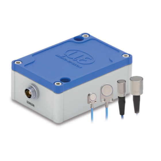
Functional Principle, Technical Data Structure The non-contact, single-channel measuring system of capaNCDT 6110 / 6120, installed in an aluminum hous- ing, consists of: - Controller - Sensor - Sensor cable - Power supply and signal cable The signal processing electronics with oscillator, demodulator, AD converter and integrated preamplifier is in... -
Page 10: Sensors
Sensors for electrical conducting targets (metals) Sensor model Measuring range Min. target diameter CS02 0.2 mm 5 mm CSH02 0.2 mm 7 mm CSH02FL 0.2 mm 7 mm CS05 0.5 mm 7 mm CSE05 0.5 mm 6 mm capaNCDT 6110 / 6120 Page 10... - Page 11 11 mm CSH2FL 2 mm 17 mm 2 mm 17 mm CSH2 2 mm 17 mm CSE2 2 mm 14 mm 3 mm 27 mm 5 mm 37 mm CS10 10 mm 57 mm capaNCDT 6110 / 6120 Page 11...
-
Page 12: Sensor Cable
The sensors of type CSH have integrated a 1.4 long sensor cable. Cable lengths of 2.8 m are available too if required. Other cable lengths are also available on request. The sensor model CSE-1 (measuring range 1 mm) has the connector type C. capaNCDT 6110 / 6120 Page 12... -
Page 13: Controller
Functional Principle, Technical Data 2.2.3 Controller The capaNCDT 6110 / 6120 contains a voltage processing, oscillator, integrated preamplifier, demodulator as well as an output level. The voltage processing produces all necessary internal voltages from the power supply. The oscillator sup- plies the sensor with frequency and amplitude-stabilized alternating voltage. -
Page 14: Technical Data
DIN EN 61326-1: 2006-10 and DIN EN 61326-2-3: 2007-5 Controller IP 40 Protection class Sensors when plugged in: IP 54 Weight 165 g RS485, 230400 Baud (adjustable), 24 bit measuring Interface values, max. 2kSamples (adjustable) FSO = Full Scale Output capaNCDT 6110 / 6120 Page 14... -
Page 15: Delivery
-50 ... +200 °C (-58 to +392 °F) ƒ Sensor cable: -50 ... +200 °C (-58 to +392 °F) ƒ Controller: -10 ... +75 °C (+14 to +167 °F) - Humidity: 5 - 95 % RH (non condensing) capaNCDT 6110 / 6120 Page 15... -
Page 16: Installation And Assembly
Grub screw Fig. 5 Radial point clamping with grub screw Do not use metal grub screws! > Danger of damaging the sensor capaNCDT 6110 / 6120 Page 16... -
Page 17: Circumferential Clamping, Cylindric Sensors
Flat sensors are mounted by means of a tap hole for M2 (in case of sensors 0.2 and 0.5 mm) or by a through hole for M2 screws. The sensors can be bolted on top or below. Screwing from above Screwing from bottom capaNCDT 6110 / 6120 Page 17... -
Page 18: Dimensional Drawings Sensors
ø20h7 (.79 dia.) ø8f7 (0.31 dia.) (inches) ø10f7 (.394 dia) ø7.7 (0.30 dia.) Circumferential clamp- ing possible from 2 mm behind the front face. Dimensional drawings of other sensors are ø10f7 (.394 dia.) available on request. capaNCDT 6110 / 6120 Page 18... - Page 19 ø30h7 (1.18 dia.) ø40h7 (1.58 dia.) (inches) Circumferential clamp- ing possible from 2 mm behind the front face. ø20h7 (.79 dia.) ø20h7 (.79 dia.) ø20h7 (.79 dia.) Dimensional drawings of other sensors are available on request. capaNCDT 6110 / 6120 Page 19...
- Page 20 ø12g6 (.473 dia.) ø8g6 (.315 dia.) ø7.5 ø11.5 (.30 dia.) (.45 dia.) ø2.2 (.09 dia.) ø2.2 (.09 dia.) Circumferential clamp- ing possible from 2 mm behind the front face. Dimensions in mm (inches), not to scale capaNCDT 6110 / 6120 Page 20...
- Page 21 Installation and Assembly CSH2-CAmx appr. 9.4 (.37) ø20g6 (.79) ø19.5 (.77) (.09) ø Dimensions in mm (inches), not to scale capaNCDT 6110 / 6120 Page 21...
- Page 22 9.4 (.37) CSH1FL-CRmx, ca. 9.4 (.37) (.16) CSH05FL-CRmx CSH1.2FL-CRmx (.003) (.16) (.24) (.003) (.16) ø3 (.22) ø3 (.29) (.12 dia.) (.12 dia.) ø2.2 ø2.2 (.09) (.09) Dimensions in mm (inches), not to scale capaNCDT 6110 / 6120 Page 22...
- Page 23 CSH2FL-CRmx (.79) ( 20) 15.5 ca. 9.4 (.61) ( 06) (appr. 37) ( 003) ø3 (.12) ø2.2 ( 09) Cable length 1.4 m visible (incl. crimp sleeve) Dimensions in mm (inches), not to scale capaNCDT 6110 / 6120 Page 23...
-
Page 24: Sensor Cable
Fig. 7 Dimensional drawings sensor cables Dimensions in mm (inches), not to scale Features of the sensor cable, see Chap. 2.2.2. 1) Sensor cable CCgxC/ CCgxB/ CCgxC/90 and CCgxB/90: Ø3.1 (.12 dia.) ±0.10 ±0.004 capaNCDT 6110 / 6120 Page 24... -
Page 25: Controller
Installation and Assembly Controller 5.5 (.22) Mounting holes for M4 screws 26.5 (1.04) 5.5 (.22) (2.09) Fig. 8 Dimensional drawing controller Dimensions in mm (inches), not to scale capaNCDT 6110 / 6120 Page 25... -
Page 26: Ground Connection, Earthing
Signal output 5-pin. female (load, min 10 kOhm) cable connector Shield Cable shield, housing SCAC3/5 is a 3 m long, pre-assembled power supply and output cable. Fig. 10 SCAC3/5 power supply and output cable capaNCDT 6110 / 6120 Page 26... -
Page 27: Power Supply, Display/Output Device Dt6120
RS485_B RS485 interface Shield Cable shield, housing SCAC3/6 is a 3 m long, pre-assembled power supply and output cable. Fig. 12 SCAC3/6 power supply and output cable Sensor Connection Fig. 13 Connection sensor cable capaNCDT 6110 / 6120 Page 27... -
Page 28: Rs485 Interface
The RS485 interface is only present with the DT6120. You can read the measuring values in digital form via the RS485 interface. MICRO-EPSILON supports you with the driver MEDAQLib, which contains all commands for the capaNCDT 6120. You can download the driver directly under the link http://www.micro-epsilon.de/link/soft-... -
Page 29: Reading Measuring Values
20 measuring values. The first measuring value in the data[] packet is the oldest value sampled, the last is the newest value sampled. capaNCDT 6110 / 6120 Page 29... -
Page 30: Scaling The Measuring Values
By default, 24-bit measuring values are transmitted. That is why: = 0 % of sensor measuring value 0xFFFFFF = 100 % of sensor measuring value If the sensor is out of measuring range, so correspondingly larger measuring values are output. capaNCDT 6110 / 6120 Page 30... -
Page 31: Example Of The Measuring Value Transmission
Data[5] 0x44 Measuring value 1 [15:8] (0x00FFFFFF = 100 %) -> 0x003244B1 = 19 % Data[6] 0x32 Measuring value 1 [23:16] e.g. 200 µm sensor -> 38,0 µm Data[7] 0x00 Measuring value 1 [31:24] capaNCDT 6110 / 6120 Page 31... -
Page 32: Setting The Rs485 Address
0xE5 No response: No response indicates that an error has occurred in the address alignment. The controller still has the old address. The new address is valid only after a reboot of the controller. capaNCDT 6110 / 6120 Page 32... -
Page 33: Commands And Settings
- RS485 address of controller: 1 … 126 - Firmware Update of controller Use for these settings either our MEDAQLib driver or the IF1032/ETH interface converter to Ethernet with the appropriate configuration option via web interface. capaNCDT 6110 / 6120 Page 33... -
Page 34: Operation
1 = Start of measuring range Sensor Target 2 = End of measuring range Fig. 14 Signal characteristic in the measuring range Disconnect the power supply before touching the sensor surface. > Static discharge > Danger of injury capaNCDT 6110 / 6120 Page 34... -
Page 35: Maintenance
94496 Ortenburg / Germany the whole measuring system back to Tel. +49 (0) 8542 / 168-0 Fax +49 (0) 8542 / 168-90 info@micro-epsilon.de www.micro-epsilon.com Sensors of the same type can be replaced without calibrating the controller. capaNCDT 6110 / 6120 Page 35... -
Page 36: Warranty
The warranty period lasts 12 months following the day of shipment. Defective parts, except wear parts, will be repaired or replaced free of charge within this period if you return the device free of cost to MICRO-EPSILON. This warranty does not apply to damage resulting from abuse of the equipment and devices, from forceful handling or installation of the devices or from repair or modifications performed by third parties. -
Page 37: Appendix
IF1032/ETH Interface module Ethernet/EtherCAT - at DT6120: RS485 to Ethernet/Ether- CAT (24-bit resolution) - at DT6110: Analog output to Ethernet/ EtherCAT (only 14-bit resolution) capaNCDT 6110 / 6120 Page 37... -
Page 38: Tilt Angle Influence On The Capacitive Sensor
Angle [°] Fig. 17 Example of measuring range deviation in the case of a sensor distance of 100 % of the measur- ing range capaNCDT 6110 / 6120 Page 38... -
Page 39: Measurement On Narrow Targets
Fig. 21 Signal change in the case of displacement of case of a sensor distance of 100 % of the measur- thin targets in the opposite direction to the measure- ing range ment direction capaNCDT 6110 / 6120 Page 39... -
Page 40: Measurements On Balls And Shafts
Figures give an influence example shown on the sensors CS05 and CS1 in the case of different sensor distances to the target as well as target diameters. As this results from internal simulations and calcula- tions, please request for detailed information. capaNCDT 6110 / 6120 Page 40... - Page 42 MICRO-EPSILON MESSTECHNIK GmbH & Co. KG X9751316-B011075HDR Königbacher Str. 15 · 94496 Ortenburg / Germany MICRO-EPSILON MESSTECHNIK Tel. +49 (0) 8542 / 168-0 · Fax +49 (0) 8542 / 168-90 *X9751316-B01* info@micro-epsilon.de · www.micro-epsilon.com...
Need help?
Do you have a question about the capaNCDT 6110 and is the answer not in the manual?
Questions and answers