Table of Contents
Advertisement
Quick Links
Advertisement
Table of Contents

Related Manuals for MICRO-EPSILON colorSENSOR CFO Series


Summary of Contents for MICRO-EPSILON colorSENSOR CFO Series
- Page 1 Instruction Manual colorSENSOR CFO100 CFO200...
- Page 2 Sensor system for testing opaque, transparent and self-luminous bodies MICRO-EPSILON Eltrotec GmbH Manfred-Wörner-Straße 101 73037 Göppingen / Germany Tel. +49 (0) 7161 / 98872-300 Fax +49 (0) 7161 / 98872-303 e-mail eltrotec@micro-epsilon.de www.micro-epsilon.com...
-
Page 3: Table Of Contents
Contents Safety ............................7 Symbols Used ..............................7 Warnings ................................7 Notes on CE Marking ............................8 Proper Use ............................... 8 Proper Environment ............................9 Functional Principle, Technical Data ..................9 Short Description ............................. 9 Measuring Principle ............................9 Functions ............................... 10 2.3.1 General ............................ - Page 4 Operation ..........................30 Commissioning .............................. 30 Membrane Keys ............................. 32 5.2.1 Keys and Key Assignments ......................33 Brief Instructions ............................34 Operation Using Foil Keyboard ........................36 5.4.1 Intensity ............................37 5.4.1.1 Automatic Level Adjustment ..................38 5.4.1.2 Manual Intensity Control ..................... 39 5.4.2 Color Management ........................
- Page 5 Instructions for Operation...................... 86 Cleaning ................................. 86 Warranty ..........................86 Service, Repair ........................87 Decommissioning, Disposal ....................87 Appendix Accessories ..........................88 Factory Settings ........................94 API Communication with Controller (Version 0.7.1) ............. 95 A 3.1 Overview ................................ 95 A 3.2 Examples of Manual Queries.........................
- Page 6 colorSENSOR CFO...
-
Page 7: Safety
Safety Safety The handling of the system assumes knowledge of the instruction manual. Symbols Used The following symbols are used in this instruction manual: Indicates a hazardous situation which results in minor or moderate injuries if not CAUTION avoided. NOTICE Indicates a situation which results in property damage if not avoided. -
Page 8: Notes On Ce Marking
(EN) listed therein. The EU declaration of conformity is kept available according to EU directive article 10 by the authorities responsible at MICRO-EPSILON Eltrotec GmbH Manfred-Wörner-Straße 101 73037 Göppingen / Germany The measuring system is designed for use in industry and satisfies the requirements. -
Page 9: Proper Environment
Functional Principle, Technical Data Proper Environment - Protection class: IP 65 - Operating temperature: -10 °C ... +55 °C - Storage temperature: -10 °C ... +85 °C - Humidity: 20 - 80 % relative humidity (non-condensing) - Ambient pressure: Atmospheric pressure The sensor is stable and can be used in a wide temperature range. -
Page 10: Functions
Functional Principle, Technical Data The transformed values (colors), are stored in the sensor and continuously compared to the current color. When the colors are all within the entered tolerance range, a recognition signal is sent to the digital switching outputs and the keyboard indicators. This process allows storage of multiple colors in various color spaces. In the same manner, the color values and the recognized color are output as data protocol via the available interfaces as required. -
Page 11: Technical Data
Functional Principle, Technical Data Technical Data Model CFO100 CFO200 Object distance Depending on optical fiber used as well as front lens attachment Reflex optical fiber typ. 2 mm - 25 mm with lens typ. 5 mm - 100 mm Light spot diameter Depending on optical fiber used as well as front lens attachment Reflex optical fiber typ. - Page 12 Functional Principle, Technical Data Model CFO100 CFO200 Power supply +18 - 28 V DC Power consumption Typ. 500 mA Max. switching current 100 mA TEACH key/inputs 5 keys and IN0 for externally teaching 5 keys and IN3 for externally teaching color reference, tolerance stage and color reference, tolerance stage and configuring sensor...
-
Page 13: Displays
Functional Principle, Technical Data Displays The sensor displays indicate the following information: - Operating mode (ON / OFF) - Current state of switching outputs - Key lock - Selected submenu The following settings are visible depending on the submenu selected: - LED intensity - Output coding - Tolerance... -
Page 14: Delivery
Delivery Delivery Unpacking/Included in Delivery colorSENSOR CFO Sensor instruction manual Carefully remove the testing system parts from the packaging and ensure furthermore that the goods are forwarded in such a way that no damage can occur. Check the delivery for completeness and shipping damage immediately after unpacking. In case of damage or missing parts, please contact the manufacturer or supplier immediately. - Page 15 Assembly 7.25 (.29) 60 (2.36) 13 (.51) 25 (.98) 15.1 (.94) (43) 19.7 (.78) NOTICE 10 (.39) Do not allow the end surfaces of the optical fiber to hit against edges or surfaces. Reduced 11 (.43) signal quality or fail- 25 (.98) ure of the measuring device.
-
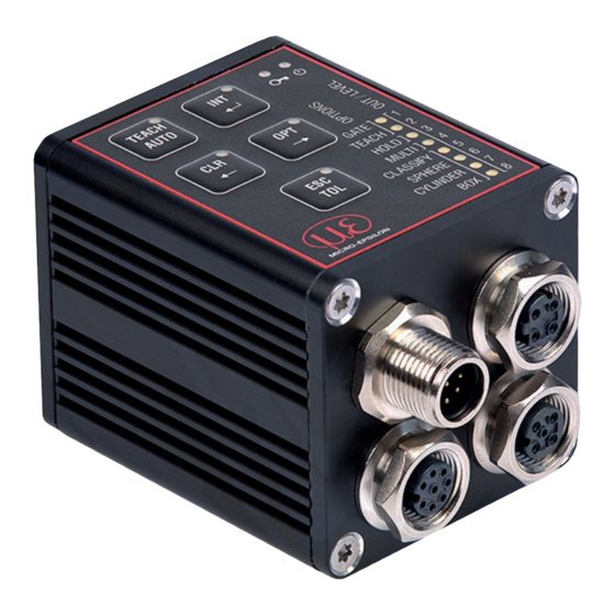
Page 16: Operating Elements
Assembly Operating Elements The operating concept, as well as the function of the foil keyboard, are described in the Chapter Foil Key- board, see Chap. 5.2. Meaning Location TEACH Teach / AUTO Automatic level adjustment Illumination intensity Enter / Save Delete Arrow pointing left Select options... -
Page 17: Sensor Leds
Assembly Sensor LEDs Eight LEDs (output indicators) are located at the bottom right edge of the keyboard. Moreover an additional LED (key indicator) is embedded in each key at the top left. The LEDs can assume the following states: - Switched off - Continuously illuminated - Various flashing rhythms Color... - Page 18 Assembly A list of increasing numbers (1 ... 8) is located to the right of the eight output LEDs, see Fig. 4. These are used to assign the eight output LEDs to the eight switching outputs available . The options are located to the left of the eight output indicators, see Fig.
-
Page 19: Electrical Connections
Assembly Electrical Connections The cable shields are connected to the connector housings. The connector housings are in contact with the controller housing. Perform all electrical connections only in the switched-off state. CAUTION > Injury hazard from high voltage Fig. 5 Connector location on Fig. -
Page 20: System, Power And Plc (Sys)
Assembly The frequently used and standardized M12 sockets allow use of standard commercial cables to match the specific, special requirements of the specific operating environment. For example, cables are available, which are oil-resistant or suitable for use with drag chains. The input and output signals from the sensor as well as the power supply and communication connections are accessible using standardized M12 connectors (male and female). -
Page 21: Ethernet (Eth)
The switching state zero is not used to ensure reliable test performance in the face of a discontinuity. The switching state all switched is recommended as the standard error output. Use shielded cable with a length < 30 m. Micro-Epsilon recommends use of CAB-M12-8P-Bu-ge cable, available as an option, see Chap. 4.4.2 Ethernet (ETH) -
Page 22: Digital I/O (I/O)
Connect the cable shield to the evaluation unit. All GND conductors are interconnected with one another and to operating voltage ground. Use shielded cable with a length < 30 m. Micro-Epsilon recommends use of the optionally available cable CAB-M12-8P-St-ge, see Chap. Color Function Description... -
Page 23: Usb
Assembly 4.4.4 It should be possible at a later time to incorporate additional communication modules via the USB interface for example, to establish a WiFi or Bluetooth connection to the sensor. Pin Color Function Description Brown USB-VDD USB (Host or Client) White USB Data- USB (Host or Client) -
Page 24: Switching Input Circuit
Assembly 4.4.5 Switching Input Circuit The switching input IN can be connected to the operating voltage potential +UB as follows. Transistor Switch Intern 47 kOhm Fig. 11 Switching input circuit (schematic) colorSENSOR CFO Page 24... - Page 25 Assembly Model CFO100 and CFO200 Color Function Description Remarks CAB-M12-8P-Bu-ge White Switchable trigger input, Not electrically separated, com- Teach reading trigger or parator input with threshold at UB/2 color +/-5 %, low level < UB/2 +/- 5 %, high level > UB/2 +/- 5 % (max. 30 V), internal pull-down resistor, open input is recognized as low.
-
Page 26: Switching Output Circuit
Assembly 4.4.6 Switching Output Circuit The switching outputs are connected as follows: Push-Pull Fig. 12 Switching output circuit (schematic) The switching behavior (NPN, PNP , Push-Pull) is programmable, see Chap. 5.7.5.4. The NPN output is, for example, suitable for adaptation to a local TTL logic circuit with auxiliary voltage of U = 5 V. - Page 27 Assembly Model CFO200 Color Function Description Remarks CAB-M12-8P-Bu-ge Yellow OUT3 Switching output switchable, Not electrically separated, 24V logic NPN, PNP , PP , outputs cor- (HTL), low level = GND, Gray OUT4 respondingly programmed, high level = +UB, I = 100 mA detected color or color group Pink OUT5...
-
Page 28: Optical Fiber, Sensor Cable
Assembly Optical Fiber, Sensor Cable Plug the optical fiber into the optical fiber connector on sensor. Fig. 13 Optical fiber connector on sensor Fig. 14 Installation of optical fiber cable The coding for the optical fiber connection (FA) is located on the illumination LED. Keep the end surfaces of the optical fiber cable free of dust, avoid any damage or soiling, e.g. - Page 29 Assembly Please observe the permissible minimum bending radius for the optical fiber used. Failure to observe the minimum bending radius (depending on the type of optical fiber used) leads to breakage of the optical fiber. Since the optical fiber cable consists of multiple fibers, breakage of any of the optical fibers leads to a reduc- tion in the illumination intensity and, in the case of signal cables, to a decrease in the measuring signal.
-
Page 30: Commissioning
Operation Operation Commissioning Connect the sensor to the optical fiber cable, see Chap. 4.5. Fig. 15 Overall view of colorSENSOR CFO with optical fiber Connect the sensor to a power supply, see Chap. 4.4.1. Switch on the power supply. After switching on the sensor, the green LED flashes and the red LED illuminates continuously as long as the sensor is booting, see Fig. - Page 31 Operation The sensor is in the operating mode when only the green Power LED is illuminated, see Fig. Fig. 17 Green LED illuminated continuously (operating mode reached) Then, depending on whether the key lock is active and colors are detected, the corresponding LEDs illumi- nate or the set output circuit for color is not detected.
-
Page 32: Membrane Keys
Operation Membrane Keys The colorSENSOR CFO can be configured using the network interface, the serial interface and the keyboard integrated into the housing. Due to the functional scope and the accessibility of the sensors, only the most important settings are accessible via the keyboard. For special applications it may therefore be necessary to use the network or serial interface to make initial settings. -
Page 33: Keys And Key Assignments
Operation 5.2.1 Keys and Key Assignments The keyboard comprises the following keys: Teach Automatic level adjustment Intensity setting Enter / save Select options Arrow pointing right Escape / Quit without saving Adapt standard tolerance Delete Arrow pointing left The inscription on the key indicates the operating function when the key is depressed for a longer period (e.g. -
Page 34: Brief Instructions
Operation Brief Instructions The instructions below do not describe any specific sequence of activity; they are simply a diverse compila- tion of typical key actuations in the operating mode, see Fig. 18 and in the menu mode, see Fig. 19. Detailed descriptions of all actions, see Chap. - Page 35 Operation Before After Action Menu mode Save all changes Depress (hold down) the ENTER key (INT) for longer than / return to 2 sec. to save the changes made previously and return to operating mode the operating mode. Menu mode Reject all Depress (hold down) the ESC key (TOL) for longer than 2 changes / return...
-
Page 36: Operation Using Foil Keyboard
Operation Operation Using Foil Keyboard Various key actions are shown below. The illustration of the LEDs reflects their state: - Continuously illuminated or off. - Flashing with various rhythms. For operation, a keyboard is depicted at the left showing the current status of all indicators as well as any key actuations. -
Page 37: Intensity
Operation 5.4.1 Intensity Adjustment of the sensor level is required after installing the sensor and, typically, following any change in the optical conditions, such as: - Distances - Alignment - Lenses Adjustment of the sensor level is required after installing the sensor and, typically, following any change in the optical conditions, such as: When adapting the intensity settings, always aim the sensor at the brightest specimen anticipated. -
Page 38: Automatic Level Adjustment
Operation 5.4.1.1 Automatic Level Adjustment The automatic level adjustment determines a suitable combination of internal sensor parameters for the cur- rent optical situation. The primary factor here is the level setting for the illumination LED: Press the AUTO key for less than 2 sec. This starts an automatic level setting process TEACH AUTO... -
Page 39: Manual Intensity Control
Operation After conclusion of the automatic level adjustment process the INT LED illumi- nates continuously. The output indicators provide for visualization of the level TEACH achieved. AUTO GATE TEACH HOLD MULTI CLASSIFY SPHERE CYLINDER 5.4.1.2 Manual Intensity Control Typically the automatic level adjustment determines a suitable combination of LED intensity, amplification and other internal settings. - Page 40 Operation After conclusion of the new level setting, the level reached is indicated by the output LEDs. TEACH AUTO GATE TEACH HOLD MULTI CLASSIFY SPHERE CYLINDER To save: Press the Enter key for longer than 2 sec. TEACH AUTO The results of the level setting are saved. The display returns to the operating mode.
-
Page 41: Color Management
Operation 5.4.2 Color Management After assembly and initial adjustment of the color sensor, see Chap. 5.4.1, the teaching process for colors or color groups can be accomplished for the recognition operation. Press the TEACH key for longer than 2 sec. The display then changes to the (color) TEACH menu. -
Page 42: Teaching Colors
Operation 5.4.2.1 Teaching Colors One or more colors can be learned for each recognition group, see Chap. 5.4.5.3. The recognition groups are differentiated according to their output coding. The 1-out-of-N codes are easily accessible via the key- board (only one of the output lines is active). Although the subsequent binary codes can be scrolled though individually, the large number of possible combinations (up to 256 for the CFO200) makes it more convenient to use an auxiliary program or the HTTP-API for this purpose. -
Page 43: Deleting Individual Color Groups
Operation 5.4.2.2 Deleting Individual Color Groups The selected recognition group is indicated by the LED flashing. Press one of the arrow keys for less than 2 sec to selected the TEACH AUTO recognition group to be deleted. Press the CLR key for longer than 2 sec. to delete the colors in the current recognition group. -
Page 44: Deleting Color Table
Operation 5.4.3 Deleting Color Table When changing to a new recognition assignment, it is recommendable to delete the color table completely. Press the CLR key for longer than 2 sec. to delete the color table completely. TEACH AUTO Output LEDs 1 - 8 flash. GATE TEACH HOLD... -
Page 45: Tolerance Setting
Operation 5.4.4 Tolerance Setting Changing the tolerance of a recognition group is an optional feature. The default tolerance is already suf- ficient for many applications. It corresponds approximately to the ability of the human eye to differentiate colors (Delta E = 4.0). The tolerance is subdivided into the following stages: Tolerance space Sphere... - Page 46 Operation Press the key as often as required, for less than 2 sec. to select the desired recognition group. TEACH AUTO GATE TEACH HOLD MULTI CLASSIFY SPHERE CYLINDER Press the TOL key for less than 2 sec. to enter the tolerance submenu. TEACH AUTO GATE...
-
Page 47: Options
Operation Press the key for less than 2 sec. to decrease the color tolerance. The changed color tolerance stage is displayed. TEACH AUTO Press the TEACH key for less than 2 sec. to return from the tolerance submenu to the color teach menu. GATE Conclusion of teach operation, see Chap. - Page 48 Operation The current sensor configuration is displayed. The currently selected GATE option (triggered color evaluation) and/or TEACH TEACH AUTO is indicated by flashing. The indicators for the selected option are visualized by flashing whereby (1900/100 ms) indicates ON and (100/1900 ms) OFF. The option menu is subdivided into four option groups: GATE TEACH...
-
Page 49: In0 Switching Input Function Assignment
Operation 5.4.5.1 IN0 Switching Input Function Assignment Using the keyboard it is possible to assign switching input IN0 to GATE for triggered color evaluation or to TEACH for triggered color teaching. If neither of the two functions is selected, the LEDs flash slowly (100/1900 ms). - Page 50 Operation Press the TEACH key for less than 2 sec. to switch the triggered color teach feature on and off via IN0. TEACH AUTO TEACH flashes slowly to signal that the triggered color teach feature is switched off. GATE flashes rapidly to signal that the triggered color teach feature is switched GATE TEACH on via IN0.
-
Page 51: Hold Time
Operation 5.4.5.2 Hold Time Extending the hold time for a recognition result beyond the actual duration of color matching is practical when the actuators controlled by the color sensor require a certain minimum hold time for the switching level. The hold time can be set to one of three different stages in the option menu. Stage Hold Time Description of LED display... -
Page 52: Multiple Teach Mode
Operation 5.4.5.3 Multiple Teach Mode The multiple teach mode allows keyboard selection of whether each recognition group may contain only the last color saved, or whether it can be assigned a number of colors. This setting has no influence on the behavior of the other user interfaces (HTTP-API or own software). -
Page 53: Tolerance Mode
Operation Press the TEACH key for less than 2 sec. to switch over to the multiple teach mode. TEACH AUTO The LED flashes rapidly (1900/100 ms) to signal that the multiple teach mode is activated. GATE TEACH HOLD MULTI CLASSIFY SPHERE CYLINDER 5.4.5.4... - Page 54 Operation Press the TEACH key for less than 2 sec. to switch to the next tolerance mode. TEACH AUTO The LED then flashes rapidly to signal the tolerance mode selected. Press the TEACH key for less than 2 sec. again to switch to the next toler- GATE ance mode.
-
Page 55: Color Tolerance Parameters
Operation 5.4.5.5 Color Tolerance Parameters The system can be set to the distance models Box (∆L; ∆a; ∆b), Cylinder (∆L; ∆ab), Sphere (∆E) and Classification. These models form a tolerance space around the learned colors. 2a*b* 2E 2a* Fig. 22 Tolerance space Fig. - Page 56 Operation A change in the color readings for one and the same specimen can have two causes: - Internal factors. Change in readings due to detector noise, changes in brightness of the light source or modulated ambient light. - External factors. Deviations in color or surface texture of specimens or in measuring conditions (distance, angle).
-
Page 57: Conclusion Of Option Settings: Save Or Quit
Operation 5.4.5.6 Conclusion of Option Settings: Save or Quit After completing the changes to the settings, they can all be stored or discarded. To save: Press the ENTER key for longer than 2 sec. to save all changed options and TEACH AUTO return to the operating mode. -
Page 58: Trigger Inputs
Operation Trigger Inputs The trigger inputs can be configured to teach new colors. Trigger inputs can be used for the following purposes: - Starting color evaluation - Teaching colors - Teaching colors as new group - Adding colors to current group - Teaching and grouping colors continuously - Deleting color table - Automatic level adjustment for sensor LED... -
Page 59: Operation Via Web Interface
Operation Operation Via Web Interface The CFO controller allows creation of dynamic web sites containing the current settings for the controller and peripheral devices. Control is possible only when an Ethernet link exists to the controller. 5.7.1 Prerequisites A current web browser is required (for example Mozilla Firefox 54, Google Chrome 60 or Microsoft Edge 14) on a PC with network connection. - Page 60 Operation Direct connection to PC, controller with static IP Network (factory setting) PC with static IP Controller with dynamic IP , PC with DHCP Connect the controller to the PC using a direct Ethernet con- Connect the controller to a switch using a direct Ethernet nection (LAN).
-
Page 61: Access Via Ethernet
Operation 5.7.2 Access via Ethernet Fig. 24 First interactive web site after calling IP address The function menus (Home, Settings, Color test and Help/Info) can now be accessed in the upper navigation bar. All settings on the web site are active immediately in the controller after pressing the Accept button. Parallel control via web browser and API commands is possible;... -
Page 62: Displaying Readings Via Web Interface
Operation 5.7.3 Displaying Readings Via Web Interface Start the reading display in the Color test menu on the horizontal navigation bar. The diagram control and display are loaded in the browser as HTML5 where they continue to run autono- mously, while the controller continues to operate independently. If you allow the diagram display to run in a separate browser tab or window, it is not necessary to restart the display each time. -
Page 63: Home Menu
Operation 5.7.4 Home Menu When the web site control is started, the Home page opens first, see Fig. The language can be set on the web sites at the top left. The language setting in your control system (PC) is taken over in the basic System settings. -
Page 64: Menu Settings
Operation 5.7.5 Menu Settings 5.7.5.1 Preliminary Remarks You can program the system using two different methods simultaneously: - Using the web browser via the control web interface - With the API commands and terminal program via RS232 or Ethernet (Telnet). After programming, save all settings permanently in a parameter set, so that they will be available again the next time you switch on the controller. -
Page 65: Recognition Profile
Operation 5.7.5.2 Recognition Profile Go to the menu Settings > Recognition Profile. In the recognition profile you can set and save the basic settings for the colorSENSOR CFO, such as color space, measuring frequency, automatic illumination setting and white reference. Fig. - Page 66 Operation Recognition Name Defines name of recognition profile. The Profile maximum name length is 64 characters and Accept may consist of only alphanumerical characters (a-z, A-Z, 0-9, no foreign character attributes), spaces and the special characters +-#,.(). Color space Selection of color space to be used for recog- CIE L*a*b*, CIE L*u‘v‘, nition.
- Page 67 Operation The measuring frequency indicates only the minimum output update. If the set measuring frequency is less than 1000 Hz, the digital outputs are still updated to a minimum of 1000 Hz. During automatic level adjustment, the lightest color to be detected should be positioned beneath the sensor.
-
Page 68: Color Table
Operation 5.7.5.3 Color Table Switch to the menu Settings > Color Table, see Fig. Depending on the version, the colorSENSOR CFO can save up to 4000 colors in up to 254 color groups in the internal color table and use them for color recognition. Model Colors Color groups... - Page 69 Operation Fig. 27 Screen shot, color table colorSENSOR CFO Page 69...
- Page 70 Operation Creating, Editing Colors Switch to the menu Settings > Color Table, see Fig. Click on the Edit button for a color group, see Fig. The Edit button allows you to make custom settings for each color group. These settings include a custom name, a tolerance model with custom tolerance values, the output circuit and the holding time for the switch- ing outputs.
- Page 71 Operation The maximum length is 64 characters and may consist of only alphanumerical characters (a-z, Color name Value A-Z, 0-9, no foreign character attributes), spaces and the special characters +-#,.(). 0 … 130 (150) Value Described by a*, b* -130 … + 130 Value Numerical value with four decimal places X, Y, Z...
- Page 72 Operation Distance Model and Tolerance Value Settings Distance model Classification / Sphere / Cylinder / Box Tolerance value ∆E* Value 0.00...50.00 ∆L* / ∆a*b* Value 0.00...50.00 ∆L* / ∆a* / ∆b* Value 0.00...50.00 Color, space, tolerances. Every color is described by the color space coordinates and the permissible toler- ance values.
- Page 73 Operation Deleting Colors, Color Table Fig. 29 Excerpt, color table click the Delete button, located on the right next To remove a complete color group from the color table to the tolerance parameters, see Fig. To remove an individual color from the color table click the Delete button, located immediately to the right of the corresponding color values.
-
Page 74: Outputs
Operation 5.7.5.4 Outputs Go to the menu Settings > Outputs. The switching characteristics of the outputs can be set in this menu point. Fig. 30 Screen shot, outputs Here it is possible to select between Off, NPN, PNP and PUSH-PULL. For details on the output circuit, see Chap. -
Page 75: Settings Ethernet
Operation 5.7.5.5 Settings Ethernet Go to the menu Settings > Ethernet settings. Fig. 31 Screen shot, Ethernet settings colorSENSOR CFO Page 75... - Page 76 Operation Ethernet set- IP settings Address type Static IP ad- When using a static IP address it is tings dress / DHCP necessary to enter the values for the IP address, Gateway and Subnet IP address Value mask; this is not required when Subnet mask Value DHCP is used.
-
Page 77: Managing Settings
Operation 5.7.5.6 Managing Settings Go to the menu Settings > Manage settings. Fig. 32 Screen shot, Manage settings colorSENSOR CFO Page 77... - Page 78 Operation All sensors settings, e.g. controller settings, colors. Ethernet settings, can be saved permanently in user programs, so-called parameters sets. Export set- Export set- Here you can ex- tings tings port all controller settings it one file Import set- Choose Controller settings Outputs, internal settings, ...
-
Page 79: Extras
Operation 5.7.5.7 Extras Go to the menu Settings > Extras. Fig. 33 Screen shot, Extras Reboot The sensor is switched off and then back on. After a firmware update, the computer restarts automatically. Factory defaults The sensor is reset to the factory default settings and the color table is deleted. For factory defaults, see Chap. -
Page 80: Color Test Menu
Operation 5.7.6 Color Test Menu Go to the Color Test menu, see Fig. The measuring data display appears. The link leads to the menu Settings > Recognition pro- Recognition Profile Link file The link leads to the menu Settings > Color table Color table Link Controls... - Page 81 Operation Fig. 34 Measuring data display colorSENSOR CFO Page 81...
- Page 82 Operation With the color test, you can record the color values for the last 10 min. and save them in a CSV file with the Save button (4), see Fig. 34 You can select and deselect the color values for depiction in the diagram (2), as well as increase the depic- tion of the measuring points from 100 % to 4000 % (5).
- Page 83 Operation The color values for the display colors in the diagram can be selected individually (3). The color test display is located on the left in the display on every menu page (1). Here the relative color of your monitor in relation to the color values for the color currently beneath the sensor (optical fiber) is displayed in a color circle.
-
Page 84: Help/Info Menu
Operation 5.7.7 Help/Info Menu Go to the Help/Info menu This page shows the version, serial number, firmware build, MAC address and web site version for the sensor used. Our contact data is also shown here if you require support or need help with the sensor or the GUI. Fig. -
Page 85: Factory Reset
Operation Factory Reset A factory reset can be accomplished as follows: Disconnect the sensor from the power supply. Hold the INT and ESC keys depressed. Avoid pressing any other keys during this procedure. Otherwise the process can become stuck in an unde- NOTICE fined state. -
Page 86: Instructions For Operation
The warranty period lasts 12 months following the day of shipment. Defective parts, except wear parts, will be repaired or replaced free of charge within this period if you return the device free of cost to MICRO-EPSILON Eltrotec. This warranty does not apply to damage resulting from abuse of the equipment and devices, from forceful handling or installation of the devices or from repair or modifications performed by third parties. -
Page 87: Service, Repair
Service, Repair Service, Repair In the event of a defect on the sensor or optical MICRO-EPSILON Eltrotec GmbH fiber, please send us the affected parts for repair or Manfred-Wörner-Straße 101 exchange. In the case of faults the cause of which 73037 Göppingen / Germany... -
Page 88: Appendix A 1 Accessories
Anhang | Accessories Appendix Accessories Designation Photo Description Part num- Mounting accessories CFO mounting For fastening 11234713 adapter colorSENSOR CFO100 or CFO200 or as replacement for colorSENSOR LT-1-LC-10 and LT-1-ST CFO DIN rail moun- Accessory for CFO mounting 11234762 ting kit adapter (Part No.: 11234713) for mounting on standard mounting rail (top hat rail TS35) - Page 89 Anhang | Accessories Designation Photo Description Part num- CFO DIN rail moun- For mounting colorSENSOR 11234763 ting adapter CFO100 or CFO200 on standard mounting rail (top hat rail TS35) Power supply cable CAB-M12-8P-Bu- Connection cable; 11234717 ge;2m-PUR;open 2 m long CAB-M12-8P-Bu- Connection cable;...
- Page 90 Anhang | Accessories Designation Photo Description Part num- CAB-M12-8P-St- Connection cable; 11234722 ge;2m-PUR;open 2 m long CAB-M12-8P-St- Connection cable; 11234723 ge;5m-PUR;open 5 m long CAB-M12-5P-St- Connection cable; 11234727 ge;2m-PUR;open 2 m long CAB-M12-5P-St- Connection cable; 11234728 ge;5m-PUR;open 5 m long CAB-M12-8P-Bu- Connection cable;...
- Page 91 Anhang | Accessories Designation Photo Description Part num- CAB-M12-8P-St- Connection cable; 11234724 ge;5m-PUR-D;open 5 m long, for use with drag chain CAB-M12-5P-St- Connection cable; 11234729 ge;5m-PUR-D;open 5 m long, for use with drag chain Power supply PS2030 Plug-in power pack 24V/24W/ 1A; 2420065 2m-PVC;...
- Page 92 Anhang | Accessories Designation Photo Description Part num- USB cable USB cable CAB- USB cable; 2 m long 11234732 M12-5P-St-ge;2m- PUR;USB USB cable CAB- USB cable; 5 m long 11234733 M12-5P-St-ge;5m- PUR;USB CAB-M12-5P-St- USB cable; 5 m long; 11234734 ge;5m-PUR-D;USB for use with drag cable Ethernet cable CAB-M12-4P-...
- Page 93 Anhang | Factory Designation Photo Description Part num- Protective caps Protective cap M12 Protective cap for covering open, 11234789 for cable box unused connection sockets to guar- antee IP 65 protection Protective cap M18 Protective cap for protection against 37930128 for FA adapter soiling illumination LED and receiver Optical fiber cable...
-
Page 94: A 2 Factory Settings
Anhang | Factory Settings Factory Settings Parameter name Value IP address 169.254.168.150 Light source LED on Exposure mode Measuring frequency 1000 Hz Triggering None, controller starts data transfer after configuration of output signals, as well as selection of interface or after diagram is called in browser. Primarily used interface Web Diagram, Color OUT (SYS, Digital I/O) Measuring program... -
Page 95: A 3 Api Communication With Controller (Version 0.7.1)
Anhang | API Communication with Controller (Version 0.7.1) API Communication with Controller (Version 0.7.1) A 3.1 Overview The HTTP-based API allows interrogation and modification of the sensor configuration and current states. All sensor details are available in this manner. For example, the integrated web application communicates with the sensor exclusively via the API. -
Page 96: A 3.4 Query Example
Anhang | API Communication with Controller (Version 0.7.1) A 3.4 Query Example Every web browser uses GET requests to fetch contents. Further request methods such as curl can be used. When used on colorS- ENSOR CFO, for example, the query curl -X GET http://169.254.168.150/api/sensor/ samples/current... -
Page 97: A 3.5 Api
Anhang | API Communication with Controller (Version 0.7.1) A 3.5 A 3.5.1 General - Collections (arrays and lists) can be queried with GET. ƒ Filtering operations using defined attributes as query parameters are possible. - Optional: Some collections allow POST requests to create additional collection elements. ƒ... - Page 98 Anhang | API Communication with Controller (Version 0.7.1) A 3.5.2 Response Format and Error Handling The API returns a data package in the following form for all requests: Data includes the actual information in reply to the specific request. Errors include errors which occurred when processing the requests.
- Page 99 Anhang | API Communication with Controller (Version 0.7.1) The attribute code describes the nature of the error using a unique string. This facilitates association of mul- tiple language error texts with error codes. The error codes are separated hierarchically by dots, for example LPLC.validation.missing_input or LCOL.autogain.invalid_target_level.
- Page 100 Text Unique identification for sensor model device id Text Serial number vendor Text Name of sensor manufacturer Example errors : data : model : “CFO100” model_key : “me_cfo_100” device_id : “7454229892” vendor : “Micro-Epsilon Eltrotec GmbH” colorSENSOR CFO Page 100...
- Page 101 Anhang | API Communication with Controller (Version 0.7.1) A 3.5.3.4 /api/firmware/images POST Creation of a firmware image with following attributes: The upload is accomplished in separate requests via /api/firmware/images/UUID/upload (see below). The approach shown above for creating an image followed by uploading individual blocks is designed for applications.
- Page 102 Anhang | API Communication with Controller (Version 0.7.1) In the event of an error, the Status Code 400 (Bad Request) is returned as early as possible after recognition of a permanent error status. Error codes: LPLC.format.malformed.upload A 3.5.3.6 api/firmware/images/UUID Requests for information on a partially or completely transferred firmware image The content of the status field is to be interpreted as follows: incomplete: Number of bytes uploaded does not yet equal number of bytes predicted.
- Page 103 Anhang | API Communication with Controller (Version 0.7.1) A 3.5.3.7 /api/firmware/images/UUID/apply POST Application of firmware image (permanent transfer to internal data storage medium) followed by sensor restart Error codes: LPLC.format.malformed.upload LPLC.internal_error A 3.5.3.8 /api/firmware/images/UUID/upload The firmware image is uploaded in data blocks (see max_chunk_size). The HTTP header Content Range is used by the client to notify the server of the range to be transferred with the current POST request.
- Page 104 Anhang | API Communication with Controller (Version 0.7.1) A 3.5.3.9 /api/firmware/recovery/upgrade-from-current Saving currently used firmware image as recovery image. This function is useful for updating an older recovery image to the latest (currently installed) status. The factory image contains only the firmware. Currently valid settings are not included. POST No attributes are expected Error codes:...
- Page 105 Anhang | API Communication with Controller (Version 0.7.1) A 3.5.3.13 /api/network/interfaces Status and collection of network interfaces available in system There are no filters. A list of dictionaries is supplied under the key network_interfaces. Each element in this list describes an interface.
- Page 106 Anhang | API Communication with Controller (Version 0.7.1) New contents can be set for the address configurations lists in the dictionary keys ipv4 and ipv6. All previous address configurations for this address family are replaced by the new list. Only the address families contained in the data configurations for the data sets are changed - all address families not men- tioned remain unchanged.
- Page 107 Anhang | API Communication with Controller (Version 0.7.1) A 3.5.3.16 /api/peripherals/emitters/HARDWARE_ID Light source query. The UUID for the light source is permissible as a selector. The following attributes are provided: Attribute Model Content hardware_id Number Unique number for light source (internal, hardware-specific) name of interface name Text...
- Page 108 Anhang | API Communication with Controller (Version 0.7.1) A 3.5.3.19 /api/peripherals/keypad/inputs Determination of keypad interface inputs present The following attributes are provided: Attribute Model Content name Text Key name capabilities Object Name of function and ULR A 3.5.3.20 /api/peripherals/keypad/inputs/NAME/up|down The URLs for each input can be queried via /api/peripherals/keypad/inputs. POST Triggering specified input action (key actuation) Error codes:...
- Page 109 Anhang | API Communication with Controller (Version 0.7.1) A 3.5.3.23 /api/sensor/capabilities The following attributes are provided: Attribute Model Content maximum_sam- Whole number Highest sample rate supported by sensor ple_rate Includes type of tolerance shape and tolerance value tolerances Object limits. output_drivers Array Includes a list of supported electrical output characteristics.
- Page 110 Anhang | API Communication with Controller (Version 0.7.1) A 3.5.3.25 /api/sensor/colorspaces/COLOR_SPACE The following attributes are provided: Attribute Model Content name Text Name of color space Axis labelling (minimum, label, maximum) axes Object space_id Text Color space ID A 3.5.3.26 /api/sensor/detectables Collection of learned color coordinates The profile_id filter allows selection of a recognition profile.
- Page 111 Anhang | API Communication with Controller (Version 0.7.1) A 3.5.3.27 /api/sensor/detectables/UUID Color coordinate query. The UUID for a color coordinate is permissible as selector. The following attributes are provided: Attribute Model Content representations Object Other representation form for color values, e.g. “RGB” for display on monitor uuid Text...
- Page 112 Anhang | API Communication with Controller (Version 0.7.1) A 3.5.3.29 /api/sensor/recognition-profiles/(UUID|current) Recognition profile query. The uuid for the profile or the magic string current is permissible as selector. Manual manipulation of the attribute sampling_settings is typically not recommendable. These are deter- mined automatically by an autogain operation.
- Page 113 Anhang | API Communication with Controller (Version 0.7.1) A 3.5.3.30 /api/sensor/recognition-profiles/(UUID|current)/autogain POST Triggering of automatic level adjustment with following (optional) parameters: Attribute Model Default value Content level Floating-point Target value for level adjustment number (between 0 and 1) minimum_sample_ Floating-point Current sample rate Desired sample rate number...
- Page 114 Anhang | API Communication with Controller (Version 0.7.1) A 3.5.3.32 /api/sensor/matchers Collection of learned recognition results The profile_id filter allows selection of a recognition profile. The standard value is current. POST All valid attributes for a PUT request are permissible for a matcher object. DELETE Deletion is permissible A 3.5.3.33 /api/sensor/matchers/UUID...
- Page 115 Anhang | API Communication with Controller (Version 0.7.1) A 3.5.3.35 Historical readings (stream=0) When further parameters are not specified, the last readings present in the buffer are returned without delay. The two optional and combinable filters min_age and max_age allow limitation of the returned entries to a defined time range (defined as seconds in comparison to time of query).
- Page 116 Anhang | API Communication with Controller (Version 0.7.1) A 3.5.3.37 /api/sensor/samples/current A query for the last recognition results is possible via this URL. If, in special situations (e.g. automatic level adjustment currently in progress or overmodulation), it is not pos- sible to capture new, valid samples, the last valid sample continues to be provided (with its old time stamp).
- Page 117 Anhang | API Communication with Controller (Version 0.7.1) A 3.5.3.38 /api/settings DELETE Sensor configuration reset Returns base64 based configuration data. POST Upload of a base64-coded configuration file (file is expected as settings_file attribute, typically as part of a multipart/form-data). Upload of a base64-coded configuration data set Error codes: LPLC.format.malformed.base64 LPLC.format.malformed.json.not_dict...
- Page 118 Anhang | API Communication with Controller (Version 0.7.1) A 3.5.3.40 /api/system/factory-reset Sensor reset to factory settings followed by reboot: Restoration of original firmware version All settings are reset It is possible to reset the settings without rebooting via /api/settings/. POST No attributes are expected Error codes: LPLC.system.action_failed...
- Page 119 Anhang | API Communication with Controller (Version 0.7.1) Error codes: LPLC.system.action_failed A 3.5.3.43 /api/system/time/zones Query for time zones available The key timezone_names provides a list of time zones (text) (e.g. Europe/Berlin). There are also time zones without slash-based grouping (e.g. UTC). A 3.5.4 Websockets A 3.5.4.1 Overview...
-
Page 120: A 3.6 Errata
Anhang | API Communication with Controller (Version 0.7.1) A 3.6 Errata The following API Endpoints are still open or not completely documented: Path Description /api/download-proxy API for provision of a payload as download /api/sensor/action-triggers End point for processing event strings colorSENSOR CFO Page 120... - Page 124 MICRO-EPSILON Eltrotec GmbH X9751375-A011079HDR Manfred-Wörner-Straße 101 · 73037 Göppingen / Germany MICRO-EPSILON Eltrotec Tel. +49 (0) 7161 / 98872-300 · Fax +49 (0) 7161 / 98872-303 *X9751375-A01* eltrotec@micro-epsilon.de · www.micro-epsilon.com...
Need help?
Do you have a question about the colorSENSOR CFO Series and is the answer not in the manual?
Questions and answers