Table of Contents
Advertisement
Quick Links
ILD2200-2
ILD2220-2
ILD2200-10
ILD2220-10
ILD2200-20
ILD2220-20
ILD2200-40
ILD2220-50
ILD2200-50
ILD2220-100
ILD2200-100
ILD2220-200
ILD2200-200
ILD2220-500
ILD2200-500
Instruction Manual
optoNCDT
22xx
ILD2210-10
ILD2200-2LL
ILD2210-20
ILD2200-10LL
ILD2212-10
ILD2200-20LL
ILD2212-50
ILD2200-50LL
ILD2220-2LL
ILD2220-10LL
ILD2220-20LL
ILD2220-50LL
Advertisement
Table of Contents

Related Manuals for MICRO-EPSILON ILD2200-2


Summary of Contents for MICRO-EPSILON ILD2200-2
- Page 1 Instruction Manual optoNCDT 22xx ILD2200-2 ILD2220-2 ILD2210-10 ILD2200-2LL ILD2220-2LL ILD2200-10 ILD2220-10 ILD2210-20 ILD2200-10LL ILD2220-10LL ILD2200-20 ILD2220-20 ILD2212-10 ILD2200-20LL ILD2220-20LL ILD2200-40 ILD2220-50 ILD2212-50 ILD2200-50LL ILD2220-50LL ILD2200-50 ILD2220-100 ILD2200-100 ILD2220-200 ILD2200-200 ILD2220-500 ILD2200-500...
-
Page 2: Ild2200
MICRO-EPSILON MESSTECHNIK GmbH & Co. KG Königbacher Strasse 15 94496 Ortenburg / Germany Tel. 08542/168-0 Fax 08542/168-90 e-mail info@micro-epsilon.de www.micro-epsilon.com Certified acc. to DIN EN ISO 9001: 2008... -
Page 3: Table Of Contents
Contents Safety ............................6 Symbols Used ..............................6 Warnings ................................6 CE Compliance ..............................7 Proper Use ................................. 8 Proper Environment ............................8 Laser Class ..........................9 Functional Principle, Technical Data ..................11 Short Description ............................. 11 Block Diagram ..............................12 Technical Data .............................. - Page 4 Measuring Setup and Commissioning ..................28 Getting Ready for Operation, Power Supply ....................28 Control and Display Elements on the Controller ..................... 29 Average Setting ..............................30 6.3.1 Averaging Number N ............................30 6.3.2 Moving Average (Default Setting) ........................31 6.3.3 Recursive Average ............................
- Page 5 Instructions for Operating ....................... 57 Reflection Factor of the Target Surface ......................57 Error Influences ..............................58 Cleaning the Protective Glasses ........................61 Value Output ..........................62 Analog Value Output ............................62 Digital Value Output, Conversion ........................62 Digital Error Codes ............................62 Software ............................
-
Page 6: Safety
Safety Safety The handling of the system assumes knowledge of the instruction manual. Symbols Used The following symbols are used in this instruction manual: Indicates a hazardous situation which, if not avoided, may result in minor or moderate injury. Indicates a situation which, if not avoided, may lead to property damage. Indicates a user action. -
Page 7: Ce Compliance
Products which carry the CE mark satisfy the requirements of the EMC regulation 2004/108/EC ‘Electromag- netic Compatibility’ and the European standards (EN) listed therein. The EC declaration of conformity is kept available according to EC regulation, article 10 by the authorities responsible at MICRO-EPSILON MESSTECHNIK GmbH & Co. KG Königbacher Straße 15... -
Page 8: Proper Use
Safety Proper Use The measuring system is designed for use in industrial areas. It is used for measuring displacement, distance, position and elongation ƒ for in-process quality control and dimensional testing ƒ The measuring system may only be operated within the limits specified in the technical data , see Chap. -
Page 9: Laser Class
Laser Class Laser Class The sensors operate with a semiconductor laser with a wavelength of 670 nm (visible/red). The laser is operated on a pulsed mode, the pulse frequency corresponding to the measuring frequency (for example f = 10 kHz). The duration of the pulse is regulated in dependency on the object to be measured and can form an almost permanent beam (for example t = 1 up to 80 μs). - Page 10 Laser Class FDA Norm The sensor complies with all applicable laws for the manufacturer of laser devices. This system is classified by the Center for Devices and Radiological Health (CDRH) asa Class II laser device. If both warning labels are covered over when the unit is installed the user must ensure that supplemen- tary labels are applied.
-
Page 11: Functional Principle, Technical Data
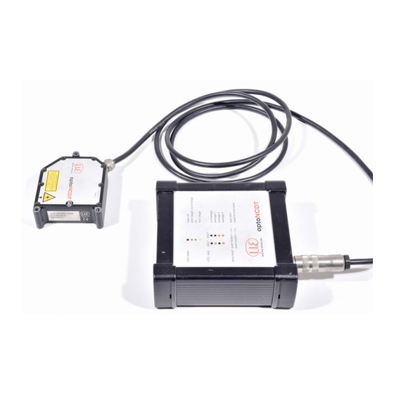
Functional Principle, Technical Data Functional Principle, Technical Data Short Description The system consists of an laser-optical sensor and a Sensor signal conditioning electronics. ILD 22xx The sensor uses the principle of optical triangulation, that is a visible, modulated point of light is projected onto the target surface. -
Page 12: Block Diagram
Functional Principle, Technical Data LEDs on the controller, see Chap. 3.4, see Chap. 6.1, LEDs on the sensor signal: signal: Out of Range (upper and lower range values) Out of Range (upper and lower range values), poor Poor Target (unfit or no object) Target (unfit or no object) Mid range In range... -
Page 13: Technical Data
Functional Principle, Technical Data Technical Data Model ILD 22xx - 2210-10 2210-20 Measuring principle Laseroptical triangulation Measuring range mm (“) (.08) (.39) (.79) (1.57) (1.97) (3.94) (7.87) (19.69) (0.39) (0.79) Start of measuring mm (“) range (.94) (1.18) (1.57) (6.89) (1.77) (2.76) (5.12) - Page 14 Functional Principle, Technical Data Model ILD22xx 2210-10 2210-20 Supply voltage 24 VAC (±15 %), max. 500 mA Standard: 2 m (6 ft) - integral Sensor cable Option: 5 m / 10 m (16 / 32 ft) Functions: Zero / Averaging Controller Dimensions: 143 x 145 x 52 mm Elektromagnetic compatibility...
-
Page 15: Operating State Of The Controller
Functional Principle, Technical Data Operating State of the Controller LED State Color LED Power green Power on Mid range yellow Poor target, out of range Laser off, see Chap. Electrical Diagram of Remote Switch for Laser On/Off The laser can be switched of with an external switch between the pins 4 and 17 for service jobs. Switching can be done with a transistor (for example open collector in an optocoupler) or a relay contact. -
Page 16: Delivery
Delivery Delivery Unpacking 1 Sensor ILD 22xx 1 Rubber feet kit for controller 1 Controller 1 25 pin Sub-D male connector with screened cable clamps 1 Instruction manual 1 CD with demo program Check for completeness and shipping damage immediately after unpacking. In case of damage or missing parts, please contact the manufacturer or supplier. -
Page 17: Installation
The ILD 22xx is an optical sensor for measurements with micrometer accuracy. Make sure it is handled care- fully when installing and operating. MICRO-EPSILON recommends the use of protective housings if the sen- sor operates in a dirty environment or higher ambient temperature, see Chap. 14.2. -
Page 18: Ild22Xx
Installation Mounting and Dimensions of 21.85 the Sensor (.86) 5.1.1 ILD22xx The sensor is mounted by means of 3 screws type M4. The laser beam must be directed per- pendicular onto the surface of the target. 24.2 36.13 Misalignment will create measuring er- (.95) (1.42) rors (indication of bigger distances). - Page 19 Installation (2.95) 3 x Mounting holes ø4.5 mm (.18 dia.) Laser spot 130 (5.12) (.59) 140 (5.51) 150 (5.91) Fig. 6 Sensor dimensions, measuring ranges: 40/200/500 mm, dimensions in mm (inches), not to scale optoNCDT 22xx Page 19...
-
Page 20: Ild2210
Installation 5.1.2 ILD2210 Center laserbeam Window Window laser objective ø4.5 (.18 dia.) 3x through 5 (.19) 81 (3.18) 140 (5.51) 145 (5.70) ILD 2210-10 ILD 2210-20 (.59) Fig. 7 Sensor dimensions ILD 2210, measuring ranges: 10/20 mm, dimensions in mm (inches), not to scale optoNCDT 22xx Page 20... -
Page 21: Free Space Of Optics
Installation Free Space of Optics 5.2.1 ILD22xx 97 (3.82) 89 (3.50) 80 (3.14) (1.18) ø4 (.16 dia.) 8 (.31) 13.4 15 (.59) (.53) 25.8 16.8 35.0 ° 40.0 ° 44.8 ° (.08) (.94) (1.02) (.66) 28.7 20.5 34.3 °... - Page 22 Installation 150 (5.91) 140 (5.51) 130 (5.12) 12 (.47) ø5 (.20 dia) 17.5 15 (.59) (.69) (1.38) Start of measuring range 22.1 ° 21.9 ° 21.8 ° (1.57) (6.89) (3.98) (3.39) 91.6 25.1 ° 16.7 ° 13.1 ° (7.87) (5.12) (3.61)
-
Page 23: Ild2212
Installation 5.2.2 ILD2210 145 (5.7) ø5 (0.20 dia.) (0.55) 15 (0.59) 16 (0.62) 32 (1.26) Start of measuring range End of measuring range Fig. 10 Free Space for the ILD2210, 10 and 20 mm, dimensions in mm (inches), not to scale 10 (0.39) 95 (6.89) 34.6 °... -
Page 24: Ild22Xxll
Installation 5.2.3 ILD22xxLL 97 (3.82) 89 (3.50) 3x Mounting holes 80 (3.15) ø4.5 mm (0.18 dia.) ø8 ø4 (0.31 dia.) 13.4 (0.16 dia.) (0.53) (0.59) Start of measuring range End of measuring range Fig. 11 Free Space for the LL, 2/10/20/50 mm, dimensions in mm (inches), not to scale 2 (0.08) 24 (0.94) -
Page 25: Sensor Cable
Installation Sensor Cable Never bend the sensor cable by more than the bending radius of 60 mm. Never lay signal leads next to or together with power cables or pulse-loaded cables (for example for drive units and solenoid valves) in a bundle or in cable ducts. Always use separate ducts. If you extend the sensor cable subsequently, this requires a re-calibration of the complete measuring system. -
Page 26: Mounting And Dimensions Of The Controller
Installation Mounting and Dimensions of the Controller 56 (2.20) 54 (2.13) ø 20 (.79 dia.) 28 (1.10) 21.2 (.83) 2 (.08) 1 (.04) 121.5 (4.78) 4 Mounting holes The controller is mounted by means of 4 screws type M4 DIN 84. When mounting the controller keep the LED displays free for watching. -
Page 27: Cable Requirement
Max. length 10 m (32 ft), the electromagnetic field may cause measurement uncertainty on the signal if you work with cables longer then 10 m (32 ft). MICRO-EPSILON recommends to terminate the end of the cable with 10 nF to avoid noise voltages. -
Page 28: Measuring Setup And Commissioning
Measuring Setup and Commissioning Measuring Setup and Commissioning Getting Ready for Operation, Power Supply Install sensor ILD 2200 and controller according to the mounting options, see Chap. Interconnect the sensor and the controller with the sensor cable. Interconnect the controller output with display or signal processing electronics. Connect the power cable to the controller. -
Page 29: Control And Display Elements On The Controller
Measuring Setup and Commissioning After switching-on of the supply voltage the sensor runs through an initialization sequence. This is indicated by the sensor state power avg 1 zero avg 3 reset momentary activation of all the LEDs and the two switching avg 2 in/out outputs. -
Page 30: Average Setting
Measuring Setup and Commissioning Average Setting The controller is supplied ex factory with the default setting „moving averaging, number of averaging N = 1“ (no averaging activated). Averaging has no effect on linearity. The controller is capable of the following different averaging methods: Moving average Recursive average Median... -
Page 31: Moving Average (Default Setting)
Measuring Setup and Commissioning After completion of the measuring cycle (every 0.1 ms for a measuring frequency of 10 kHz) the internal average is calculated again and outputted. For digital outputs, averaging has no effect on the measuring frequency/data frequency. Further numbers of averaging can be programmed using the digital interface, see Chap. -
Page 32: Recursive Average
Measuring Setup and Commissioning Example: N = 4 ... 0, 1, 2, 2, 1, 3 ... 1, 2, 2, 1, 3, 4 Measurement values 2+2+1+3 2+1+3+4 (n+1) Output value The first average value is output when N measurement values have been reached. The output frequency stays constant at 10 kHz. -
Page 33: Comparison And Impact Of Averaging
Measuring Setup and Commissioning 6.3.5 Comparison and Impact of Averaging The effect of internal averaging in the controller is to provide an improvement in the output signal for: Measurement objects with much less backscattering than the reference material Measurement objects with structured surfaces, that is sheet metal or scratched surfaces Although this does not offer any influence on linearity, it does improve the resolution and stability of the measurements on the aforementioned surfaces. - Page 34 Measuring Setup and Commissioning Example 2: Metal part with unbalance N = 1 N = 1 Recursive Moving N = 128 N = 128 Recursive Moving Recursive averaging Moving averaging Impact: Reduction in surface noise and vibration Impact: Reduction in surface noise but retention of amplitude the vibration amplitude Applications: Measurements on non-profiled belt-...
- Page 35 Measuring Setup and Commissioning Example 3: Averaging with median Measurement object: Rotating metal part with low unbalance and slight scratching No average Median MW3 Median MW9 Non-averaged output signal: Averaging: Averaging: In the adjacent diagram both the N = 3 (Number of averaging) N = 9 (Number of averaging background noise (speckles) and The measurement curve is...
-
Page 36: Setting The Average Mode
Measuring Setup and Commissioning 6.3.6 Setting the Average Mode Press and hold the AVG key on the controller. Switch on the controller. Averaging mode Status AVG 1 Moving AVG 2 AVG 1 Recursive AVG 2 AVG 1 Median Front view of the AVG 2 controller Fig. -
Page 37: Adjustment Of Zero-Point
Measuring Setup and Commissioning The averaging mode is then saved. For verification purposes the selected combination (avg1/avg2) will flash again for a moment. Following this the controller will start up (boot) as normal, indicated by the momentary illumination of the other LEDs. The controller is then ready in measuring mode with the selected averaging method. -
Page 38: Pin Assignment 25-Pin. Sub-D Connector
Measuring Setup and Commissioning Pin Assignment 25-pin. Sub-D Connector Assignment Comment Color PC1800- PC2200-x PC1800-3 3/10/RS485 +24 VDC Supply voltage is galvanically insu- Supply ground lated from the system blue Ground Analog signal green appr. 100 Ohm, R 1 MOhm, Signal ground ≤... -
Page 39: Error Output Circuit
Measuring Setup and Commissioning Error Output Circuit The error messages Error 1 and Error 2 are sent for example if there is low reflection or high penetration depth of the laser light into the target. It applies the following allocation: Pin on Sub-D 21 (+) POOR Target (unfit or no object) -
Page 40: Synchronization
Measuring Setup and Commissioning Synchronization For thickness measurement with two sensors it is essential that the two sensors measure at the same time. A time delay during the recording of the measurement corresponds to a displacement of the measurement ob- ject, that means the sensors measure at different positions. -
Page 41: Responses Of The Analog Output To Errors
Measuring Setup and Commissioning Controller 1 Controller 2 Controller 3 Controller n PC1800-3/10/RS485(05) PC1800-3/10/RS485(06) PC1800-3(05) PC1800-3(06) PC1800-3/10/RS485(05) PC1800-3/10/RS485(07) PC1800-3/10/RS485(06) PC1800-3(05) PC1800-3(10) PC1800-3(06) PC1800-3/10/RS485(05) PC1800-3/10/RS485(07) PC1800-3/10/RS485(07) PC1800-3/10/RS485(06) PC1800-3(05) PC1800-3(10) PC1800-3(10) PC1800-3(06) PC2200-x PC2200-x PC2200-x PC2200-x Master Slave Slave Slave Fig. 21 Required cables to synchronize two, three or more controllers. -
Page 42: Timing
Measuring Setup and Commissioning Release the Zero/Reset key when the required output response is shown. The output response is then saved. For verification purposes the selected combination (avg1/avg2) will flash again for a moment. Following this the controller will start up (boot) as normal, indicated by the momentary illumination of the other LEDs. -
Page 43: Pin Assignment For Rs422 Connection
Measuring Setup and Commissioning Cycle Time 100 µs (50 µs) 200 µs (100 µs) 300 µs (150 µs) 400 µs (200 µs) Exposure N Output N 1. Layer Reading N Computing N (Output N-3) (Exposure N + 3) Exposure N+1 2. -
Page 44: Serial Interface Rs422
Serial Interface RS422 Serial Interface RS422 PC2200-x/IF2008 The controller has a digital inter- face (RS485). The system can be operated with a PC through the interface unit IF2008 (avail- able as an option). IF2008 Fig. 24 System structure to operate the interface card IF2008 Pin Signal Required cables and program Signal... -
Page 45: Data Format
Result of the conversion: D14 D13 D12 D11 For the data transfer with a PC the MICRO-EPSILON IF2008 PCI BUS interface card is suitable. This can be connected to the controller via the PC2200-x/IF2008 interface cable, which is also available as an option. -
Page 46: Setup Of The Commands
Serial Interface RS422 Setup of the Commands The commands for the sensor are transmitted in full duplex mode. Each commando packet is made of inte- ger multiple 32 bit words. 4 consecutive bytes are combined to a 32 bit word as most of the serial interfaces use a data format of 8 bits. - Page 47 Serial Interface RS422 Format, Example: 24 23 16 15 Contents “+“ “+“ “+“ 0x0d (“CR“) 0x2B2B2B0D Start word “I“ “L“ “D“ “1“ 0x494C4431 Identifier ID (“ILD1“) Command (0x2075) 0x20 0x75 0x00 0x03 0x20750003 Package length = 3 2 top bits = 0 0x00 0x00 0x00...
-
Page 48: Command Reply, Communication Without Error
Serial Interface RS422 7.2.1 Command Reply, Communication without Error No start word is transmitted, if the sensor replies to a command. The 1st word then is the sensor identifier. The second word is the command with set MSB (Bit 31 = 1, corresponding an OR operation of the com- mand with 0x8000) and the new package length, if there was no error during communication. -
Page 49: Information Command
Serial Interface RS422 Example: Sensor operates in the average mode “Median“. The command AVGn is not possible in this opera- tion mode and leads to the following answer. 24 23 16 15 Contents “I“ “L“ “D“ “1“ 0x494C4431 Identifier ID (“ILD1“) 0x2075 OR 0xC000 0xE0 0x73... -
Page 50: Average Command 0..3
Serial Interface RS422 Format: Response: 24 23 16 15 24 23 16 15 “+“ “+“ “+“ 0x0D 0x2B2B2B0D “I“ “L“ “D“ “1“ 0x494C4431 “I“ “L“ “D“ “1“ 0x494c4431 0xA0 0x66 0x00 0x20 0xA0660002 0x20 0x66 0x00 0x02 0x20660002 0x20 0x20 0x0D 0x0A 0x20200D0A... -
Page 51: Average Command N
Serial Interface RS422 Average Command n Name AVG n Description: Averaging is set and the LED‘s are off. Format: Response: 24 23 16 15 24 23 16 15 “+“ “+“ “+“ 0x0D 0x2B2B2B0D “I“ “L“ “D“ “1“ 0x494C4431 “I“ “L“ “D“... -
Page 52: Reset Command
Serial Interface RS422 Format: Response: 24 23 16 15 24 23 16 15 “+“ “+“ “+“ 0x0D 0x2B2B2B0D “I“ “L“ “D“ “1“ 0x494C4431 “I“ “L“ “D“ “1“ 0x494C4431 0xA0 0x7d 0x00 0x02 0xA07D0002 0x20 0x7d 0x00 0x03 0x207D0003 0x20 0x20 0x0D 0x0A 0x20200D0A... -
Page 53: Stop Command
Serial Interface RS422 7.10 Stop Command Name STOP Description: Output of data via serial output is stopped Format: Response: 24 23 16 15 24 23 16 15 “+“ “+“ “+“ 0x0D 0x2B2B2B0D “I“ “L“ “D“ “1“ 0x494C4431 “I“ “L“ “D“ “1“... - Page 54 Serial Interface RS422 Format: Response: 24 23 16 15 24 23 16 15 “+“ “+“ “+“ 0x2B2B2B0D “I“ “L“ “D“ “1“ 0x494C4431 “I“ “L“ “D“ “1“ 0x494C4431 0xA0 0x4A 0x00 0x0C 0xA04A000C 0x20 0x4A 0x00 0x02 0x204A0002 Measuring frequency 0x00 0x00 0x00 0x0X...
-
Page 55: Laser Off
Serial Interface RS422 7.12 Laser off Name LASER_OFF Description: Switch off the laser Format: Response: 24 23 16 15 24 23 16 15 “+“ “+“ “+“ 0x0D 0x2B2B2B0D “I“ “L“ “D“ “1“ 0x494C4431 “I“ “L“ “D“ “1“ 0x494C4431 0xA0 0x86 0x00 0x02 0xA0860002... -
Page 56: Reaction Time
Serial Interface RS422 7.15 Reaction Time Data output Begin of answer is stopped Stop command Last byte of completely received answer sent by by sensor sensor 10 ... 20 ms 600 µs 10 ms 10 ms Send stop-command Delay inside of Output of answer sensor before output of answer... -
Page 57: Instructions For Operating
Instructions for Operating Instructions for Operating Reflection Factor of the Target Surface In principle the sensor evaluates the diffuse part of the reflected laser light, see Fig. 29. A statement concern- ing a minimum reflectance is difficult to make, because even a small diffuse fraction can be evaluated from highly reflecting surfaces. -
Page 58: Error Influences
Instructions for Operating Error Influences Color differences Because of intensity compensation, color difference of targets affect the measuring result only slightly. How- ever, such color differences are often combined with different penetration depths of the laser light into the material. Different penetration depths then result in apparent changes of the measuring spot size. Therefore color differences in combination with changes of penetration depth may lead to measuring errors. - Page 59 Instructions for Operating Angle influence laser on Tilt angles of the target both around the X and t te the Y axis of less than 5 ° only have a disturbing optoNCDT effect with surfaces which are highly reflecting. Tilt angles between 5 ° and 15 ° lead to an apparent distance change of approximately 0.12 ...
- Page 60 Instructions for Operating Optimising the measuring accuracy by Color strips Direction of movement means of special sensor arrangement In case of rolled or polished metals that are moved past the sensor the sensor plane must be arranged in the direction of the rolling or grinding marks.
-
Page 61: Cleaning The Protective Glasses
Instructions for Operating Cleaning the Protective Glasses A periodically cleaning of the protective housings is recommended. Dry cleaning This requires a suitable optical antistatic brush or blow off the panels with dehumidified, clean and oil free compressed air. Wet cleaning Use a clean, soft, lint-free cloth or lens cleaning paper and pure alcohol (isopropanol) for cleaning the protec- tive housing. -
Page 62: Value Output
Value Output Value Output Analog Value Output Calculation of a value: Max. range (with offset) -10.0 V ... +10.0 V 10.0 V = 100 % measuring Output amplification DU Measuring range [mm] range x [mm] = U 10.0 [V] Output voltage without offset -5.0 V ... -
Page 63: Software
Software Software 10.1 Demo Software The software transfers sensor parameter to the sensor and transmits measuring results and represent them in a diagram. All data are transmitted through a RS422 interface and can be saved on demand. Disconnect or connect the D-sub connection between RS422 and USB converter when the sensor is disconnected from power supply only. -
Page 64: Measurement
Software 10.1.3 Measurement Fig. 34 Start screen of the measurement program This sub program can be used to acquire, evaluate and store data. You will find the latest driver /program routine at: www.micro-epsilon.com/link/opto/2200 optoNCDT 22xx Page 64... -
Page 65: Software Support With Medaqlib
(commands), provides a consistant transmission format for all MICRO-EPSILON sensors. For C/C++ programmers MEDAQLib contains an additional header file and a library file, You will find the latest driver / program routine at: www.micro-epsilon.com/download... -
Page 66: Warranty
MICRO-EPSILON. The warranty period lasts 12 months following the day of shipment. Defective parts, except wear parts, will be repaired or replaced free of charge within this period if you return the device free of cost to MICRO-EPSILON. -
Page 67: Appendix
Appendix Appendix 14.1 Accessories, Service PS2020 Power supply 24 V for mounting on DIN-rail, input 230 VAC, output 24 VDC/2.5 IF2008 Interface card with RS422 interface for up to 4 sensors ILD22xx and two encoders SGH 1800 Protection housing with glass window for sensors ILD22xx-2 / 10 / 20 / 50 / 100 SGHF 1800 Protection housing with glass window and air cleaning of the glass window for sensors ILD22xx-2 / 10 / 20 / 50 / 100... -
Page 68: Protective Housing
Appendix 14.2 Protective Housing The SGH protective housing are designed to be used especially if the sensor operates in a dirty environment or higher ambient temperature. It is available as an accessory. If these protective housings are used, the lin- earity of the sensors in the complete system may deteriorate. - Page 69 Appendix Protective housing SGH1800 Dimensions in mm (inches), Laser not to scale spot 140 (5.51) 103 (4.06) For SGH2200 (.16) (.20) (Without air purging) Exhaust air connector 25.5 (1.00) Laser spot For SGHF2200 (Air purging) Closed with blind plug (.22) 4 Mounting holes ø4.5 (.18 dia.) Sensor cable Air inlet (Air supply can be pivoted, for...
- Page 70 Appendix Protective housing SGH2200 Dimensions in mm (inches), not to scale Laser spot 4 Mounting holes For SGHF2200 4 (.16) ø4.5 (.18 dia.) (Air purging) Closed with blind plug For SGH2200 Laser spot (Without air purging) 25.5 Exhaust air connector (1.00) Sensor cable with connector 6.5 (.26)
-
Page 71: Factory Setting
Appendix 14.3 Factory Setting Press the key “zero/reset“ for about 5 seconds to restore the factory settings. Name/Function Setting Chapter Moving average, averaging number Averaging Chap. N = 1, without averaging Responses of the analog Save the last valid measurement Chap. - Page 72 MICRO-EPSILON MESSTECHNIK GmbH & Co. KG X9751090-D061092HDR Königbacher Str. 15 · 94496 Ortenburg / Germany MICRO-EPSILON MESSTECHNIK Tel. +49 (0) 8542 / 168-0 · Fax +49 (0) 8542 / 168-90 *X9751090-D06* info@micro-epsilon.de · www.micro-epsilon.com...
Need help?
Do you have a question about the ILD2200-2 and is the answer not in the manual?
Questions and answers