Table of Contents
Advertisement
Quick Links
CT-SF
CTM-1
CTF
CTM-2
MICRO-EPSILON MESSTECHNIK GmbH & Co. KG
CTH
CTM-3
Koenigbacher Str. 15 · 94496 Ortenburg / Germany
Tel. +49 (0) 8542 / 168-0 · Fax +49 (0) 8542 / 168-90
info@micro-epsilon.com · www.micro-epsilon.com
Your local contact:
Operating Instructions
thermoMETER
CTP-3
CTP-7
www.micro-epsilon.com/contact/worldwide/
CT
Advertisement
Table of Contents

Related Manuals for MICRO-EPSILON thermoMETER CT Series


Summary of Contents for MICRO-EPSILON thermoMETER CT Series
- Page 1 CT-SF CTM-1 CTP-3 CTM-2 CTP-7 MICRO-EPSILON MESSTECHNIK GmbH & Co. KG CTM-3 Koenigbacher Str. 15 · 94496 Ortenburg / Germany Tel. +49 (0) 8542 / 168-0 · Fax +49 (0) 8542 / 168-90 info@micro-epsilon.com · www.micro-epsilon.com Your local contact:...
- Page 2 Infrared sensor MICRO-EPSILON MESSTECHNIK GmbH & Co. KG Koenigbacher Str. 15 94496 Ortenburg / Germany Tel. +49 (0) 8542 / 168-0 Fax +49 (0) 8542 / 168-90 info@micro-epsilon.com www.micro-epsilon.com...
-
Page 3: Table Of Contents
Contents Safety ............................7 Symbols Used ..............................7 Warnings ................................7 Notes on CE Marking ............................8 Intended Use ..............................9 Proper Environment ............................9 Laser Safety ..........................10 Technical Data ........................11 Functional Principle ............................11 Sensor Models ............................... 12 General Specifications ........................... - Page 4 Ground Connection ............................36 7.4.1 CTM Models ..........................36 7.4.2 CT-SF, CT-CF, CTF, CTH, CTP Models ..................37 Exchange of the Sensor ..........................38 7.5.1 Entering of the Calibration Code ....................38 7.5.2 Sensor Cable ..........................39 Outputs and Inputs ......................... 40 Analog Outputs ..............................
- Page 5 Relays Outputs .............................. 66 Functional Inputs ............................67 Alarms ................................68 8.5.1 Output Channel 1 and 2 (Channel 2 on CT-SF / CTP-7 and CTP-3) ..........68 8.5.2 Visual Alarms ..........................68 8.5.3 Open Collector Output / AL2 ......................69 Operating ..........................
- Page 6 Service, Repair ........................86 Decommissioning, Disposal ....................86 Appendix Accessories ..........................87 A 1.1 Mounting Accessories ........................... 87 A 1.2 Air Purge Collars ............................89 A 1.2.1 Standard Air Purge Collar ......................89 A 1.2.2 Laminar Air Purge Collar ......................90 A 1.3 CF Lens and Protective Window ........................
-
Page 7: Safety
Safety Safety System operation assumes knowledge of the operating instructions. Symbols Used The following symbols are used in these operating instructions. Indicates a hazardous situation which, if not avoided, may result in minor or moder- ate injury. Indicates a situation that may result in property damage if not avoided. Indicates a user action. -
Page 8: Notes On Ce Marking
Safety Protect the sensor cable against damage. > Destruction of the sensor, failure of the measuring device Do not kink the sensor cable and bend the sensor cable in tight radius. The minimum bending radius is 14 mm (static). A dynamic movement is not allowed. >... -
Page 9: Intended Use
Safety Intended Use - The thermoMETER CT is designed for use in industrial and laboratory areas. It is used for non-contact temperature measurement. - The system must only be operated within the limits specified in the technical data, see 3. - The sensor must be used in such a way that no persons are endangered or machines and other material goods are damaged in the event of malfunction or total failure of the controller. -
Page 10: Laser Safety
Laser Safety Laser Safety The optional available laser-sighting tools (TM-LST-CT and TM-LSTOEM-CT) for thermoMETER CT, see A 1.4.4, operate with a semiconductor laser with a wavelength of 500 ... 650 nm (visible/red). The laser fall within laser class 2 (II). The maximum optical power is ≤ 1 mW. Observe the laser protection regulations. -
Page 11: Technical Data
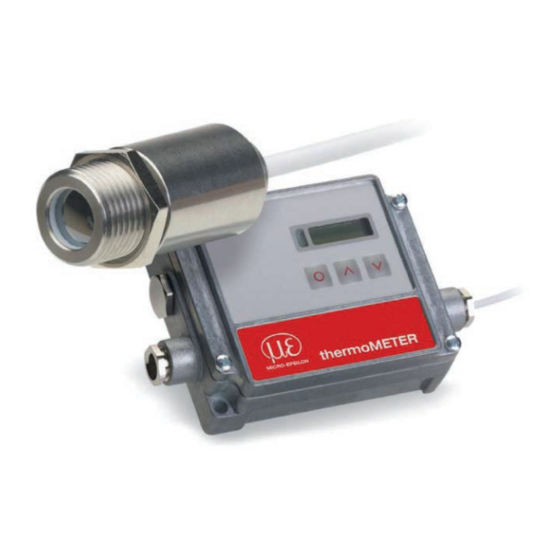
Technical Data Technical Data Functional Principle The sensors of the thermoMETER CT series are non-contact measuring infrared temperature sensors. They calculate the surface temperature based on the emitted infrared energy of objects, see 13 The sensor housing of the thermoMETER CT is made from stainless steel (protection class. IP 65/ NEMA 4), the controller is placed in a separate box made of die casting zinc. -
Page 12: Sensor Models
Technical Data Sensor Models Model Model codes Measuring range Spectral response Typical applications CT-SF02 / CT-SF15 -50 to 600 °C 8 - 14 μm Non-metallic surfaces CT-SF22 -50 to 975 °C CTF-SF15 / -50 to 975 °C 8 - 14 μm Fast processes CTF-SF25 CTH-SF02 /... -
Page 13: General Specifications
Technical Data General Specifications Sensor Controller Protection class IP 65 Ambient temperature See also Chapter Measurement 0 ... 85 °C (+32 ... +185 °F) Specification, see 3.5 Only CTP-3: 0 ... 75 °C (+32 ... +167 °F) Storage temperature See also Chapter Measurement -40 ... -
Page 14: Electrical Specifications
Technical Data Electrical Specifications Power supply 8 - 36 VDC Current draw max. 100 mA Outputs/ analog selectable: 0/4 - 20 mA, 0 - 5/10 V, thermocouple (J or K) or Channel 1 alarm output (Signal source: object temperature) Channel 2 Sensor temperature [-20 ... -
Page 15: Measurement Specifications
Technical Data Measurement Specifications 3.5.1 CT Model Model CT-SF02 CT-SF15 CT-SF22 Temperature range (scalable) -50 ... 600 °C -50 ... 600 °C -50 ... 975 °C Ambient temperature (sensor) -20 ... 130 °C -20 ...180 °C -20 ...180 °C Storage temperature (sensor) -40 ... -
Page 16: Ctf / Cth Models
Technical Data 3.5.2 CTF / CTH Models Model CTF-SF15 CTF-SF25 CTH-SF02 CTH-SF10 Temperature range (scalable) -50 ... 975 °C -50 ... 975 °C -40 ... 975 °C -40 ... 975 °C Ambient temperature (sensor) -20 ... 120 °C -20 ... 120 °C -20 ... -
Page 17: Ctm Models
Technical Data 3.5.3 CTM Models Model CTM-1SF40 CTM-1SF75 CTM-1SF75H1 CTM-2SF40 Temperature range 485 ... 1050 °C 650 ... 1800 °C 800 ... 2200 °C 250 ... 800 °C (scalable) Ambient temperature -20 ... 100 °C -20 ... 100 °C -20 ... 100 °C -20 ... - Page 18 Technical Data Model CTM-2SF75 CTM-2SF75H1 CTM-3SF22 CTM-3SF33 Temperature range (scalable) 385 ... 1600 °C 490 ... 2000 °C 50 ... 400 °C 100 ... 600 °C Ambient temperature Sensor -20 ... 125 °C -20 ... 85 °C Controller 0 ... 85 °C Storage temperature Sensor -40 ...
- Page 19 Technical Data Model CTM-3SF75H1 CTM-3SF75H2 CTM-3SF75H3 Temperature range (scalable) 150 ... 1000 °C 200 ... 1500 °C 250 ... 1800 °C Ambient temperature Sensor -20 ... 85 °C Controller 0 ... 85 °C Storage temperature Sensor -40 ... 85 °C Controller -40 ...
-
Page 20: Ctp Models
Technical Data 3.5.4 CTP Models Model CTP-7 CTP-3 Temperature range (scalable) 0 ... 710 °C 50 ... 400 °C Ambient temperature Sensor -20 ... 85 °C -0 ... 75 °C Controller 0 ... 85 °C -0 ... 75 °C Storage temperature Sensor -40 ... -
Page 21: Delivery
Delivery Delivery Unpacking 1 thermoMETER CT sensor 1 Controller 1 Connection cable 1 Mounting nut 1 Instruction manual Check the delivery for completeness and shipping damage immediately after unpacking. In case of damage or missing parts, please contact the manufacturer or supplier. Optional accessories you will find in the Chapters - Mounting Accessories, see A 1.1... -
Page 22: Optical Charts
Optical Charts Optical Charts The following optical charts show the diameter of the measuring spot in dependence on the distance between measuring object and sensor. The spot size refers to 90 % of the radiation energy. The distance is always measured from the front edge of the sensor. The size of the measuring object and the optical resolution of the infrared thermometer determine the maximum distance between sensor and measuring object. - Page 23 Optical Charts CT-CF22 Optics: CF integrated D:S: 22:1 2.3mm@ 50mm D:S (far field) = 6:1 CT-SF15 CTF-SF15 CTP-3 Optics: SF D:S: 15:1 CT-CF15 Optics: CF integrated D:S: 15:1 3.0mm@ 50mm D:S (far field) = 5:1 thermoMETER CT Page 23...
- Page 24 Optical Charts CTH-SF10 CTP-7 Optics: SF D:S: 10:1 CTH-CF10 Optics: CF1 integrated D:S: 10:1 3.0mm@ 30mm D:S (far field) = 3:1 thermoMETER CT Page 24...
- Page 25 Optical Charts CT-SF02 CTH-SF02 Optics: SF D:S: CTM-1CF40 CTM-2CF40 Optics: CF integrated D:S: 40:1 2.7mm@ 110mm D:S (far field) = 12:1 thermoMETER CT Page 25...
- Page 26 Optical Charts CTM-1SF40 CTM-2SF40 Optics: SF D:S: 40:1 CTM-1CF75 CTM-1CF75H1 CTM-2CF75 CTM-2CF75H1 CTM-3CF75H1 CTM-3CF75H2 CTM-3CF75H3 Optics: CF integrated D:S: 75:1 1.5mm@ 110mm D:S (far field) = 14:1 thermoMETER CT Page 26...
- Page 27 Optical Charts CTM-1SF75 CTM-1SF75H1 CTM-2SF75 CTM-2SF75H1 CTM-3SF75H1 CTM-3SF75H2 CTM-3SF75H3 Optics: SF D:S: 75:1 CTM-3SF22 Optics: SF D:S: 22:1 CTM-3CF1-22 Optics: CF1 integrated D:S: 22:1 1.5mm@ 30mm D:S (far field) = 3.5:1 thermoMETER CT Page 27...
- Page 28 Optical Charts CTM-3SF22 Optics: CF D:S: 22:1 5mm@ 110mm D:S (far field) = 9:1 CTM-3SF33 Optics: SF D:S: 33:1 CTM-3CF1-33 Optics: CF1 D:S: 33:1 1.0mm@ 30mm D:S (far field) = 4:1 thermoMETER CT Page 28...
- Page 29 Optical Charts CTM-3CF33 Optics: CF D:S: 33:1 3.4mm@ 110mm D:S (far field) = 11:1 thermoMETER CT Page 29...
-
Page 30: Mechanical Installation
Mechanical Installation Mechanical Installation The thermoMETER CT sensors are equipped with a metrical M12x1-thread and can be installed either directly via the sen- sor thread or by means of the hex nut (included in scope of supply) to the mounting bracket available. Various mounting brackets which make the adjustment of the sensor easier can be ordered additionally as accessories. - Page 31 Mechanical Installation 45 (1.77) 40 (1.57) (.16) Make sure to keep the optical path clear of any objects. 39 (1.54) (.39) Fig. 4 Dimensional drawing massive housing (standard on CTH and CTP), dimensions in mm (inches), not to scale thermoMETER CT Page 31...
- Page 32 Mechanical Installation 30 (1.18) 110 (4.33) 92 (3.6) 22 (.87) 4 (.16) 13 (.51) M12x1.5 4 (.16) 89 (3.5) max. 120 (4.72) Fig. 5 Controller, dimensions in mm (inches), not to scale Fig. 6 Controller with closed cover [TM-COV-CT] The controller is also available with closed cover (no access to display and programming keys from outside) [TM-COV-CT], see Fig.
-
Page 33: Electrical Installation
Electrical Installation Electrical Installation Cable Connections For the electrical installation of the thermoMETER CT, please open at first the cover of the controller (4 screws). Below the display are screw terminals for the cable connection. 7.1.1 Pin Assignment 7.1.1.1 CT-SF02, CT-SF15, CT-SF22, CTF-SF15, CTF-SF25, CTH-SF02, CTH-SF10, CTP-7 and CTP-3 Models Designation +8 ... -
Page 34: Models
Electrical Installation 7.1.1.2 CTM-1, CTM-2, CTM-3 Models Designation +8 ... 36 VDC Power supply Ground (0 V) of power supply Ground (0 V) of internal in- and outputs Alarm 2 (Open collector output) OUT-TC Analog output thermocouple (J or K) OUT-mV/mA Analog output object temperature (mV or mA) F1-F3... -
Page 35: Cable Assembling
Electrical Installation Cable Assembling The cable gland M12x1.5 of the controller allows the use of cables with an outer diameter of 3 to 5 mm. Remove the isolation from the cable (40 mm power supply, 50 mm signal outputs, 60 mm functional inputs). -
Page 36: Ground Connection
Electrical Installation Ground Connection 7.4.1 CTM Models At the bottom side of the main board PCB you will find a connector (jumper), which has been placed from factory side as shown in the picture (lower and middle pin connected), see Fig. 10. -
Page 37: Ct-Sf, Ct-Cf, Ctf, Cth, Ctp Models
Electrical Installation 7.4.2 CT-SF, CT-CF, CTF, CTH, CTP Models At the bottom side of the main board PCB you will find a connector (jumper), which has been placed from factory side as shown in the picture (lower and middle pin connected), see Fig. -
Page 38: Exchange Of The Sensor
Electrical Installation Exchange of the Sensor From factory side the sensor has already been connected to the controllers and the calibration code has been entered. Inside the model group CT-SF22, CT-SF15, CT-SF02, CTH-SF10, CTH-SF02 any exchange of sensors and controllers is possible. The sensors and controllers of the models CTF-SF15 and CTF-SF25 can- not be exchanged. -
Page 39: Sensor Cable
Electrical Installation For entering the code, please press the key (keep them pressed) and then the key, see Fig. The display shows HCODE and then the 4 signs of the first block. With each sign can be changed. Please type in your specific calibration code of the sensor. You can switch to the next sign or next block with . -
Page 40: Outputs And Inputs
Outputs and Inputs Outputs and Inputs Analog Outputs The thermoMETER CT has one or two analog output channels. Please do never connect a supply voltage to the analog outputs. The thermoMETER CT is not a 2-wire sen- sor! > Destruction of output 8.1.1 Output Channel 1 This output is used for the object temperature. -
Page 41: Digital Interfaces
Outputs and Inputs Digital Interfaces All CT sensors can be optionally equipped with an USB-, RS232-, RS485-, Profibus DP-, CAN-Bus-, Modbus RTU- or Ethernet interface. In the case that you want to use the delivered cable gland M12x1.5 for the interface cable, please disassem- ble the terminal block and assemble them again. -
Page 42: Usb Interface
Outputs and Inputs 8.2.1 USB Interface 8.2.1.1 Installation Mount the USB adapter, see 8.2. Make sure the wiring is correct according to the wire colors printed on the interface board. For industrial installations it is recommended to connect the shield of the USB adapter cable with the control- ler housing (inside the cable gland). -
Page 43: Rs232 Interface
Outputs and Inputs 8.2.2 RS232 Interface 8.2.2.1 Installation Mount the RS232 adapter, see 8.2. Make sure the wiring is correct according to the drawing and designation printed on the interface board, see 13. The CT always needs an external power supply for operation. 8.2.2.2 Software Installation Please install the CompactConnect software, see 11. -
Page 44: Rs485 Interface
Outputs and Inputs 8.2.3 RS485 Interface 8.2.3.1 Installation Mount the RS485 adapter, see 8.2. The RS485-USB adapter is providing a 2-wire half-duplex mode. Please connect terminal A of the interface with terminal A of the next RS485 interface and so on, see Fig. -
Page 45: Sensor Installation
Outputs and Inputs 8.2.3.2 Sensor Installation Each CT unit connected to the RS485 needs a different multidrop address (1 ... 32). button until M xx appears in the display. Please adjust the address by pressing the Using the Up and Down keys you can change the shown address (xx) The address can also be changed with the CompactConnect software. -
Page 46: Profibus Interface
Outputs and Inputs 8.2.4 Profibus Interface 8.2.4.1 Installation Mount the Profibus adapter, see Chap. 7.2. Make sure the wiring is correct, see Fig. We recommend for industrial installations to connect the shield of the Profibus cable with the controller housing (inside the cable gland). The thermoMETER CT always needs an external power supply. -
Page 47: Commissioning Profibus
Outputs and Inputs 8.2.4.2 Commissioning Profibus Read in the „IT010A90.gsd“ GSD file, contained on the delivered CompactConnect software CD, into the PLC configuration tool and configure the controller. At least one module must be selected. You will find more information about the Profibus interface on the enclosed CompactConnect software CD, page 18. -
Page 48: Can Bus Interface
Outputs and Inputs 8.2.5 CAN BUS Interface Mount the CAN BUS adapter, see 8.2. Make sure the wiring is correct, see Fig. 18. We recommend for industrial installations to connect the shield of the CAN BUS cable with the control- ler housing (inside the cable gland). - Page 49 B4: DA B5: 07 T = 20.10 °C Before delivery, MICRO-EPSILON can set parameters, desired by the customer, for an extra charge. For the subsequent conversion a CAN master is required. Diagnosis If the power supply is on, the LED displays one of the following conditions:...
-
Page 50: Modbus Rtu
Outputs and Inputs 8.2.6 Modbus RTU 8.2.6.1 Serial Interface Parameters Baud rate: 9600 or 19200, set by user (factory default: 9600) Data bits: Parity: even Stop bits: Flow control: off 8.2.6.2 Protocol The protocol is a Modbus RTU protocol. 8.2.6.3 Installation Overview Insert the Modbus RTU interface on the CT electronic board and power it with 8 - 36 V. - Page 51 Outputs and Inputs Modbus RTU interface on CT electronic board 8 - 36 V Fig. 21 Installation Modbus RTU interface on thermoMETER CT electronic board thermoMETER CT Page 51...
- Page 52 Outputs and Inputs Use a Modbus RTU program to read out the data, see Fig. This is done via the Read Holding Registers and Read Input Registers, see Fig. Fig. 22 View Modbus RTU program Fig. 23 View dropdown menu Modbus RTU program thermoMETER CT Page 52...
-
Page 53: Connection Of More Than One Device (Synchronisation)
In order to communicate, each device needs its own ID. The numbers 1 to 247 can be selected. 8.2.6.5 Overview of Digital Commands for Modbus RTU Digital Interfaces for CT and CTLaser Sensors The command overview is available online on the product side of the sensor at: https://www.micro-epsilon.de/download/manuals/man--thermoMETER-ct-ctlaser-modbus-rtu-commands--en. thermoMETER CT Page 53... -
Page 54: Ethernet Interface
Outputs and Inputs 8.2.7 Ethernet Interface 8.2.7.1 Installation Mount the Ethernet adapter, see 8.2. In case you want to run the pre-mounted cable of the Ethernet box through the delivered cable gland, the terminal block has to be disassembled/assembled. The thermoMETER CT always requires an external power supply of at least 12 V. Make sure the wiring is correct according to the colors printed on the interface board. - Page 55 Outputs and Inputs Fig. 24 View CompactConnect CD-ROM Now install the device driver by selecting Install Ethernet Driver. thermoMETER CT Page 55...
- Page 56 Outputs and Inputs Select Add New Device and press Weiter. The IP and MAC address of the Ethernet adapter will appear in the list. You will find the MAC address also printed on the Ethernet adapter. Please mark the adapter in the list and press Weiter.
- Page 57 Outputs and Inputs The following screen shows all settings. The device will be installed inside the network. Please press Fertig stellen. thermoMETER CT Page 57...
-
Page 58: Uninstalling The Ethernet Adapter In A Network
Outputs and Inputs 8.2.7.3 Uninstalling the Ethernet Adapter in a Network In the upper overview all on the PC installed To deinstall an adapter please follow the steps de- Ethernet adapter are shown. scribed under Network Installation, see 8.2.7.2. Select Remove an Existing Device and Select the adapter(s) which should be dein- stalled and press Weiter. -
Page 59: Direct Connection To A Pc
Outputs and Inputs 8.2.7.4 Direct Connection to a PC If a direct connection between Ethernet adapter and PC is required both have to be connected via a cross- over cable. In addition the adapter and the PC need to get a fixed IP address. Please open the Windows device manager after the network installation (Start/Control panel/ System/Hardware/Device manager). - Page 60 Outputs and Inputs In the input mask Use the following IP address below you can now enter a fixed IP address. thermoMETER CT Page 60...
- Page 61 Outputs and Inputs Confirm your settings with Apply. For a communication with the adapter you now have to configure the network settings on your PC. Please open the LAN settings (Start/Control panel/Network settings/Settings). thermoMETER CT Page 61...
- Page 62 Outputs and Inputs Mark the LAN connection and open the properties window using the right mouse button. thermoMETER CT Page 62...
- Page 63 Outputs and Inputs Double click on Internetprotokoll/In- Please enter here a fixed IP address for the ternet protocol (TCP/IP). Please note that the first three blocks (ex- ample: 192.168.049) have to match with the IP address of the adapter device. Press OK.
-
Page 64: Settings Inside The Compactconnect Software
Outputs and Inputs 8.2.7.5 Settings inside the CompactConnect Software Furthermore you should set the Communication After a successful network installation of the mode Standard (menu: Measurement/ Ethernet adapter you can start the CompactConnect software. Settings). To make sure that an available device can be found This activates the so called polling mode (bi- you should first activate the function Scan non-... -
Page 65: Resetting The Ethernet Adapter
Outputs and Inputs 8.2.7.7 Resetting the Ethernet Adapter The Ethernet adapter can be reset to the factory setting. Please use a ballpoint pen to press the Reset button (hole at the top of the housing). Switch on the power supply while pressing the Reset button. After a few seconds you will see a flashing green LED (network connection). -
Page 66: Relays Outputs
Outputs and Inputs Relays Outputs The thermoMETER CT can optionally be equipped with a relay output. The relay board is installed the same way as the digital interfaces, see 8.2. Connect the external electrical circuit with the terminal blocks. A simultaneous installation of a digital interface and the relay outputs is not possible. The switching thresholds correspondent with the values for alarm 1 and 2, see 8.5, see 3.5.2, and are factory-... -
Page 67: Functional Inputs
Outputs and Inputs Functional Inputs The three functional inputs F1 - F3 can be programmed with the CompactConnect software, only. F1 (digital) Trigger (a 0 V - level on F1 resets the hold functions) F2 (analog) e = 0.1; 9 V e = 1;... -
Page 68: Alarms
Outputs and Inputs Alarms The thermoMETER CT has following alarm features: All alarms (alarm 1, alarm 2, output channel 1 and 2 if used as alarm output) have a fixed hysteresis of 2 K (CThot: 1 K). 8.5.1 Output Channel 1 and 2 (Channel 2 on CT-SF / CTP-7 and CTP-3) The respective output channel has to be switched into digital mode for activation. -
Page 69: Open Collector Output / Al2
Outputs and Inputs 8.5.3 Open Collector Output / AL2 +24 V +24 V CT / CTlaser Relais +24 V AL 2 Fig. 26 Open collector output / AL2 Fig. 27 Open collector output / AL2 circuit diagram The transistor acts as a switch. In case of alarm, the contact is closed. A load/consumer (relay, LED or a resistor) must always be connected. -
Page 70: Operating
Operating Operating After powering up the supply voltage the sensor starts an initializing routine for some seconds. During this time the display will show INIT. After this procedure the object temperature is shown in the display. The display backlight color changes according to the alarm settings, see 8.5, see 8.5.2. - Page 71 Operating Display Mode [Sample] Adjustment range P---- Signal output peak hold [inactive] P---- = inactive / 0.1 ... 999.9 s / P ∞ ∞ ∞ ∞ = infinite V---- Signal output valley hold [inactive] V---- = inactive / 0.1 ... 999.9 s / V ∞ ∞ ∞ ∞ = infinite u 0.0 Lower limit temperature range [0 °C]...
-
Page 72: Sensor Setup
Operating Sensor Setup The programming keys enable the user to set the sensor on-site. The current measuring value or the chosen feature is displayed. With the operator obtains the chosen feature, with the functional parameters can be selected – a change of parameters will have immediate effect. If no key is pressed for more than 10 seconds the display automatically shows the calculated object temperature (ac- cording to the signal processing). -
Page 73: Explanation To The Menu Items
Operating Explanation to the Menu Items Display Description Selection of the output signal. By pressing the different output signals can be selected, see 9.1. EO.970 Setup of emissivity. Pressing increases the value; decreases the value (also valid for all further functions). The emissivity (e - Epsilon) is a material constant factor to describe the ability of the body to emit infrared energy, see 14. - Page 74 Operating Fig. 29 Signal graphs with P--- Red graph TProcess with peak hold (hold time = 1 s) Blue graph TActual without post processing Display Description u 0.0 Setup of the lower limit of temperature range. The minimum difference between lower and upper limit is 20 K.
- Page 75 Operating Display Description ] 5.00 Setup of the upper limit of the signal output. This setting allows an assignment of a certain sig- nal output level to the lower limit of the temperature range. The adjustment range corresponds to the selected output mode (e.g. 0 - 5 V). U °C Setup of the temperature unit [°C or °F] / 30.0...
-
Page 76: Error Messages
Operating Error Messages The display of the thermoMETER CT can show the following error messages: 9.4.1 CT-SF02, CT-SF15, CT-SF22, CTH and CTP Models OVER Object temperature too high UNDER Object temperature too low ^^^CH Sensor temperature to high vvvCH Sensor temperature to low 9.4.2 CTM-1, CTM-2, CTM-3 Models 1. -
Page 77: Instructions For Operation
Instructions for Operation Instructions for Operation 10.1 Cleaning Lens cleaning: Blow off loose particles using clean compressed air. The lens surface can be cleaned with a soft, humid tissue moistened with water or a lens cleaner (e.g. Purosol or B+W Lens Cleaner). Never use cleaning compounds which contain solvents (neither for the lens nor for the housing). -
Page 78: Compactconnect Software
CompactConnect Software CompactConnect Software Insert the CompactConnect installation CD into the according drive on your computer. If the auto run option is activated the installation wizard will start automatically. Otherwise, please start CDsetup.exe from the CD-ROM. Follow the instructions of the wizard until the installation is finished. The installation wizard will place a launch icon on the desktop and in the start menu. -
Page 79: Communication Settings
Communication Settings Communication Settings 12.1 Serial Interface Baud rate: 9.6 ... 115.2 kBaud (adjustable on the unit or via CompactConnect software) Data bits: Parity: none Stop bits: Flow control: 12.2 Protocol All sensors of the CT series are using a binary protocol. They can be switched alternatively to an ASCII proto- col. -
Page 80: Ascii Protocol
Communication Settings 12.3 ASCII Protocol The models CT-SF02, CT-SF15, CT-SF22, CTH-SF02, CTH-SF10 can be switched to ASCII by changing the first figure of block 3 of the sensor calibration code. This figure has to be changed from 0 to 4 (old sensor) respectively 8 to C (new sensor) (always +4;... -
Page 81: Saving Of Parameter Settings
Communication Settings 12.4 Saving of Parameter Settings After switching on the CT sensor, the flash mode is active. This means that changed parameter settings will be saved in the CT-internal Flash-EEPROM and will also be kept after the sensor is switched off. In case values should be changed quite often or continuously the flash mode can be switched off by using the following command: Decimal:... -
Page 82: Basics Of Infrared Thermometry
Basics of Infrared Thermometry Basics of Infrared Thermometry Depending on the temperature each object emits a certain amount of infrared radiation. A change in the temperature of the object is accompanied by a change in the intensity of the radiation. For the measurement of “thermal radiation”... -
Page 83: Emissivity
Emissivity Emissivity 14.1 Definition The intensity of infrared radiation, which is emitted by each body, depends on the temperature as well as on the radiation features of the surface material of the measuring object. The emissivity (e – Epsilon) is used as a material constant factor to describe the ability of the body to emit infrared energy. -
Page 84: Characteristic Emissivity
Emissivity 14.3 Characteristic Emissivity In the case that none of the methods mentioned above help to determine the emissivity you may use the emissivity tables, see A 3, see A 4. These are only average values. The actual emissivity of a material de- pends on the following factors: - Temperature - Measuring angle... -
Page 85: Liability For Material Defects
Within this period, defective parts, except for wearing parts, will be repaired or replaced free of charge, if the device is returned to MICRO-EPSILON with shipping costs prepaid. Any damage that is caused by improper handling, the use of force or by repairs or modifications by third parties is not covered by the liability for mate- rial defects. -
Page 86: Service, Repair
Service, Repair Service, Repair If the sensor, controller or the sensor cable is defec- MICRO-EPSILON MESSTECHNIK tive, please send us the affected parts for repair or GmbH & Co. KG exchange. Koenigbacher Str. 15 94496 Ortenburg / Germany If the cause of a fault cannot be clearly identified, please send the entire measuring system to: Tel. -
Page 87: Appendix A 1 Accessories
Appendix | Accessories Appendix Accessories A 1.1 Mounting Accessories The mounting bracket [TM-FB-CT] is adjustable in The mounting bold [TM-MB-CT] with M12x1 thread one axis. is adjustable in one axis. Fig. 31 Mounting bracket [TM-FB-CT] Fig. 32 Mounting bold [TM-MB-CT] The mounting fork [TM-MG-CT], adjustable in two The mounting bracket, adjustable in two axes axes, can be combined with the mounting bracket... - Page 88 Appendix | Accessories KF40 flange (TM-KF40GE-CT) with Ge window or TM-KF40B270-CT for CTM-1, CTM2, CTM3 with B270 win- Fig. 35 KF40 flange (TM-KF40GE-CT); explosion graphics When changing the screws during assembly, tighten the screws to 1 Nm tightening torque. thermoMETER CT Page 88...
-
Page 89: A 1.2 Air Purge Collars
Appendix | Accessories A 1.2 Air Purge Collars Avoid disposals (dust, particles) on the lens as well as smoke, haze and high humidity (condensation). > Error measurements These effects can be reduced by using an air purge collar. Make sure to use oil-free technically clean air, only. A 1.2.1 Standard Air Purge Collar Standard air purge collar [TM-AP-CT] for CT-SF22,... -
Page 90: Laminar Air Purge Collar
Appendix | Accessories A 1.2.2 Laminar Air Purge Collar The sideward air outlet TM-APL-CT prevents a cool- A combination of the laminar air purge collar with ing down of the object in short distances. the bottom section of the mounting fork TM-MG-CT allows an adjustment in two axes. -
Page 91: A 1.3 Cf Lens And Protective Window
Appendix | Accessories A 1.3 CF Lens and Protective Window The optional CF lens allows the measurement of very small objects and can be used in combination with the CT-SF02, CT-SF15, CT-SF22, CTM-1, CTM-2, CTM-3 models. The minimum spot size depends on the used sensor. - Page 92 Appendix | Accessories If the protective window is used, the transmission has to be set as follows (average values): 0.83 [CT-SF02/CT-SF15/CT-SF22] or 0.93 [CTM-1, CTM-2, CTM-3]. Fig. 40 CF lens [TM-CF-CT] Fig. 41 Laminar air purge with Fig. 42 CF lens [TM-CFAG-CT] respectively protective window integrated CF lens respectively protective window...
- Page 93 Appendix | Accessories CTF-SF25 + CF lens 0.5 mm @ 8 mm 0.5 mm @ 6 mm [TM-APLCF-CT] D:S (far field) = 1.6:1 CT-SF22 + CF lens 0.6 mm @ 10 mm 0.6 mm @ 8 mm [TM-APLCF-CT] D:S (far field CF) = 1.5:1 CT-SF15/ CTF-SF15 + CF lens 0.8 mm @ 10 mm 0.8 mm @ 8 mm [TM-APLCF-CT]...
- Page 94 Appendix | Accessories CTH-SF10 + CF lens 1.2 mm @ 10 mm 1.2 mm @ 8 mm [TM-APLCF-CT] D:S (far field) = 1.2:1 CT-SF02 / CTH-SF02 + CF lens 2.5 mm @ 23 mm 2.5 mm @ 21 mm [TM-APLCF-CT] D:S (far field) = 5:1 thermoMETER CT Page 94...
-
Page 95: A 1.4 Further Accessories
Appendix | Accessories A 1.4 Further Accessories A 1.4.1 Right Angle Mirror The right angle mirror [TM-RAM-CT] for optics with D:S ≥ 10:1 enables measurements with 90 ° angle to sen- sor axis. Fig. 43 Right angle mirror [TM-RAM-CT] The mirror has a reflection of 96 % in combination with a CT-SF22 and CT-SF15 and 88 % with a CTF-SF15. If the mirror is used this value has to be multiplied by the emissivity value of the measurement object. -
Page 96: Rail Mount Adapter For Controller
Appendix | Accessories A 1.4.2 Rail Mount Adapter for Controller With rail mount adapter the CT controller can be mounted easily on a DIN rail (TS35) according to EN50022. Fig. 44 Rail mount adapter for controller [TM-RAIL-CT] A 1.4.3 Tilt Assembly for CT Sensors With this mounting accessory a fine adjustment of the CT sensor with an off-axis angle ±6,5 °... -
Page 97: Laser Sighting Tool
Appendix | Accessories A 1.4.4 Laser Sighting Tool The laser sighting tool [TM-LST-CT], battery powered (2x Alkaline AA), for alignment of CT sensors. The laser head has similar mechanical dimensions as the CT sensor. Laser radiation. Irritation or injury of the eyes possible. -
Page 98: Oem Laser Sighting Tool
Appendix | Accessories A 1.4.5 OEM Laser Sighting Tool The OEM laser sighting tool is available with 3.5 m [TM-LSTOEM-CT] and 8 m connection cable [TM-LSTO- EM-CT (008)]. The laser can be connected to the pins 3V SW and GND, see Chap. and switched on and off via the programming keys or via the CompactConnect software. -
Page 99: Massive Housing
Appendix | Accessories A 1.4.6 Massive Housing The massive housing [TM-MHS-CT] is available in aluminum (anodized) or brass. Fig. 50 Massive housing, stainless steel [TM-MHS-CT] Fig. 51 Dimensional drawing massive housing, stainless steel Dimensions in mm (inches), not to scale The massive housing allows reproducible and stable measurements on applications with significant and short-term variation in ambient temperatures. -
Page 100: A 1.4.7 Accessories For Massive Housing
Appendix | Accessories A 1.4.7 Accessories for Massive Housing Fig. 53 Air purge collar for massive housing Fig. 54 Mounting bracket for massive housing, ad- (thread M18x1) [TM-APMH-CT] justable in one axis [TM-FBMH-CT] The needed amount of air (approx. 2 ... 10 l/ min.) depends on the application and the installation conditions on-site. -
Page 101: A 1.4.9 Pipe Adapter And Sighting Tubes
Appendix | Accessories A 1.4.8 A 1.4.9 Pipe Adapter and Sighting Tubes The pipe adapter [TM-PA-CT] allows an assembling of sighting tubes directly on the CT sensor. The sighting tubes are available in 3 different lengths: TM-ST20-CT Length: 20 mm TM-ST40-CT Length: 40 mm TM-ST88-CT... -
Page 102: A 2 Factory Settings
Appendix | Factory Settings Factory Settings The devices have following presettings at time of delivery: Signal output object temperature 0 - 5 V Emissivity 0.970 (CTP-3, CTP-7)/1.000 (CTM-1, CTM-2, CTM-3) Transmissivity 1.000 Averaging (AVG) 0.2 s (CTF: 0.1 s)/(CTM-1, CTM-2, CTM-3: 0.001 s) Smart Averaging inactive/(CTF, CTM-1, CTM-2, CTM-3: active) Peak hold (MAX) - Page 103 Appendix | Factory Settings Model CT-SF02/15/22/ CTM-1SF40 CTM- CTM-1SF75H1 CTM- CTM- CTF/CTH 1SF75 2SF40 2SF75 Lower limit temperature range [°C] Upper limit temperature range [°C] 1050 1800 2200 1600 Lower alarm limit [°C] 1200 (normally closed) Upper alarm limit [°C] 1400 1600 1200...
-
Page 104: Emissivity Table Metals
Appendix | Emissivity Table Metals Emissivity Table Metals Please note that these are only approximate values, which were taken from various sources. Material Typical Emissivity Spectral response 1.0 μm 1.6 μm 5.1 μm 8 - 14 μm Aluminum Non oxidized 0.1 - 0.2 0.02 - 0.2 0.02 - 0.2... - Page 105 Appendix | Factory Settings Material Typical Emissivity Spectral response 1.0 μm 1.6 μm 5.1 μm 8 - 14 μm Iron Non oxidized 0.35 0.1 - 0.3 0.05 - 0.25 0.05 - 0.2 Rusted 0.6 - 0.9 0.5 - 0.8 0.5 - 0.7 Oxidized 0.7 - 0.9 0.5 - 0.9...
- Page 106 Appendix | Emissivity Table Non Metals Material Typical Emissivity Spectral response 1.0 μm 1.6 μm 5.1 μm 8 - 14 μm Steel Polished plate 0.35 0.25 Rustless 0.35 0.2 - 0.9 0.15 - 0.8 0.1 - 0.8 Heavy plate 0.5 - 0.7 0.4 - 0.6 Cold-rolled 0.8 - 0.9...
-
Page 107: A 4 Emissivity Table Non Metals
Appendix | Emissivity Table Non Metals Emissivity Table Non Metals Please note that these are only approximate values which were taken from various sources. Material Typical Emissivity Spectral response 1.0 μm 2.2 μm 5.1 μm 8 - 14 μm Asbest 0.95 Aphalt 0.95... - Page 108 Appendix | Smart Averaging Material Typical Emissivity Spectral response 1.0 μm 2.2 μm 5.1 μm 8 - 14 μm Snow Soil 0.9 - 0.98 Textiles 0.95 0.95 Water 0.93 Wood Natural 0.9 - 0.95 0.9 - 0.95 thermoMETER CT Page 108...
-
Page 109: A 5 Smart Averaging
Appendix | Smart Averaging Smart Averaging The average function is generally used to smoothen the signal curves. With the adjustable parameter time this function can be optimal adjusted to the respective application. One disadvantage of the average function is that fast temperature peaks which are caused by dynamic events are subjected to the same averaging time. - Page 110 MICRO-EPSILON MESSTECHNIK GmbH & Co. KG X9751190-B082050HDR Koenigbacher Str. 15 · 94496 Ortenburg / Germany Tel. +49 (0) 8542 / 168-0 · Fax +49 (0) 8542 / 168-90 MICRO-EPSILON MESSTECHNIK info@micro-epsilon.com · www.micro-epsilon.com *X9751190-B08* Your local contact: www.micro-epsilon.com/contact/worldwide/...
Need help?
Do you have a question about the thermoMETER CT Series and is the answer not in the manual?
Questions and answers