Table of Contents
Advertisement
Quick Links
Advertisement
Table of Contents

Related Manuals for MICRO-EPSILON optoNCDT ILR 1191


Summary of Contents for MICRO-EPSILON optoNCDT ILR 1191
- Page 1 Instruction Manual optoNCDT ILR 1191 ILR 1191-300...
- Page 2 Laser-based distance sensor MICRO-EPSILON MESSTECHNIK GmbH & Co. KG Königbacher Strasse 15 94496 Ortenburg / Germany Tel. +49 (0) 8542 / 168-0 Fax +49 (0) 8542 / 168-90 e-mail info@micro-epsilon.de www.micro-epsilon.com Certified acc. to DIN EN ISO 9001: 2008...
-
Page 3: Table Of Contents
Trigger In/Out ..........................26 SSI Interface ..............................27 Profibus ................................28 RS232 and RS422 Interface ....................29 Properties ............................... 29 Commands ..............................29 Data Decoding Binary Format ........................31 6.3.1 Displacement Measurement ......................31 6.3.2 Speed Measurement ........................33 optoNCDT ILR 1191... - Page 4 QA – Analog Output ........................50 10.3.15 BR – Baud Rate ..........................50 10.3.16 SD – Serial Interface Termination Character ................51 10.3.17 TE – Serial Interface Termination Character ................. 52 10.3.18 SC – Format SSI ........................... 53 optoNCDT ILR 1191...
- Page 5 Malfunctions, Error Messages ....................58 12.1 Malfunctions ..............................58 12.2 Operating Advice ............................58 12.3 Error Messages .............................. 58 Decommissioning, Disposal ....................58 Warranty ..........................59 Optional Accessory ........................ 60 Factory Settings ........................61 Maintenance ........................... 62 optoNCDT ILR 1191...
- Page 6 ILR 1191 Page 6...
-
Page 7: Safety
Cable connectors must not be plugged or unplugged, as long as voltage is supplied. Remember to turn volt- age supply off before you begin working on cable connections. > Damage to or destruction of the sensor optoNCDT ILR 1191 Page 7... -
Page 8: Notes On Ce Identification
> Failure of the measuring device Information and warning signs must not be removed. Notes on CE Identification The following applies to optoNCDT ILR 1191: - EU directive 2004/108/EC - EU directive 2011/65/EU, “RoHS“ category 9 Products which carry the CE mark satisfy the requirements of the quoted EU directives and the European standards (EN) listed therein. -
Page 9: Proper Use
- Operating temperature: -40 up to +60 °C (-40 to +140 °F) - Storage temperature: -40 up to +70 °C (-40 to +158 °F) - Humidity: < 65 % (no condensation) - Ambient pressure: atmospheric pressure optoNCDT ILR 1191 Page 9... -
Page 10: Laser Class
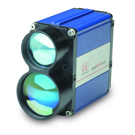
Laser Class Laser Class The optoNCDT ILR 1191 sensor operates with semiconductor lasers for measurement and adjustment of the sensor. Laser class Laser type, wavelength Measuring laser 1 (I) infrared, 905 nm, invisible EN60825-1:2003-10 beam divergence: 1.7 mrad Pilot laser for... - Page 11 CLASS 2 LASER PRODUCT EN 60825-1: 2007 =635 nm P=1 mW CW =905 nm Q=210 nJ t=10 ns f=2 kHz Fig. 1 True reproduction of the sensor with its actual location of the warning label optoNCDT ILR 1191 Page 11...
-
Page 12: Functional Principle, Technical Data
Commissioning of the sensor is straightforward due to a variety of interfaces and easy mounting options. The optoNCDT ILR 1191 is fitted with an integrated heater for outdoor use. A pilot laser is also integrated for mounting and adjustment. -
Page 13: Status Display
Profibus inactive green supply voltage on; Profibus works Fig. 3 Status display - functions 1) In the DM operation mode (single distance measurement) the target characteristics are not displayed, see Chap. 10.3.16. optoNCDT ILR 1191 Page 13... -
Page 14: Technical Data
LOW < 1 V, with R < 100 kOhm, residual current about 5 µA HIGH = supply voltage - 1 V Trigger input trigger edge and – delay programmable, trigger pulse max. 30 V optoNCDT ILR 1191 Page 14... - Page 15 EN 61326-1: 2006 and EN 61010-1: 2001 1) Depending on target reflectivity, stray light effects and atmospheric conditions 2) Statistical spread of 95 % 3) Distance range to the target being measured: 0.5 m up to 700 m to the sensor optoNCDT ILR 1191 Page 15...
-
Page 16: Models, Equipment Features
[4] Profibus- OUT, M12 female [3] M12 male, dummy [5] Profibus- IN, M12 male Fig. 4 Rear panel of the various sensor models Notice: For reasons of sealing, plug [3] is also installed for ILR 1191-300(03) (SSI). optoNCDT ILR 1191 Page 16... -
Page 17: Delivery
Delivery Delivery Supplied Items, Unpacking 1 Sensor optoNCDT ILR 1191-300 1 Instruction manual 1 CD-ROM with GSD file and instruction manual Optional accessories, separately packed: 1 Power supply-/output cable PC11xx with 2 m up to 30 m length (subject to order) -
Page 18: Installation And Mounting
Installation and Mounting Installation and Mounting The sensor optoNCDT ILR 1191-300 is an optical sensor for measurements with millimeter accuracy. Make sure it is handled carefully when installing and operating. Sensor Mounting 90.4 (3 56) 123.4 (4.86) 17.5 thread M4 (0 69) 90.4... -
Page 19: Reflector Mounting
2, reference 6, supports the sensor alignment to a given target during commission- ing. It qualifies as a class 2 (II) laser device and operates at 635 nm (red) in the visible range. The pilot laser optoNCDT ILR 1191 Page 19... - Page 20 Move the sensor at a very short distance to the reflector (for example < 1 m). The light spot is located in the lower left corner of the reflector. Move the sensor with the longest range to the reflector. Check the position of the light spot at the reflec- tor and set it if necessary. optoNCDT ILR 1191 Page 20...
-
Page 21: Electrical Connections
Different cable sets with open ends are optionally available. Bending radius of the supply and output cable PC11x (available as an optional accessory): - 47 mm (once) - 116 mm (permanent) optoNCDT ILR 1191 Page 21... -
Page 22: Analog Output
The analog output allows standardized analog data transfers from or to a remote location over greater dis- tances using a two-wire transmission line. The current which is injected into this line at levels from 4 mA to optoNCDT ILR 1191 Page 22... - Page 23 - The distance of a moving target is to be measured in a range of 20 m up to 250 m. At a distance of 20 m the sensor is to output 20 mA. Command to the sensor: QA250 20 optoNCDT ILR 1191 Page 23...
-
Page 24: Rs232/Rs422 Interface
The purpose of Q1 and Q2 is to represent distance readings as logic operation data. They report events of positive or negative deviation of a preset switching range with a certain amount of hysteresis. Accordingly, they are perfectly suited for direct reprocessing of monitored quantities such as filling level or for detection of optoNCDT ILR 1191 Page 24... - Page 25 - z = 0, decreasing distance ƒ Output switches from HIGH to LOW , if w + x -y/2 is fallen below. ƒ Output switches from LOW to HIGH, if w - y/2 is fallen below. optoNCDT ILR 1191 Page 25...
-
Page 26: Trigger In/Out
Parameter settings for trigger input can be made via the serial interface. The command to achieve this is TDx_y (where “_” is equivalent to space, 0x20 hex), see Chap. 10.3.11. green max. 30 V Target Status Link red/blue Fig. 16 Wiring trigger input optoNCDT ILR 1191 Page 26... -
Page 27: Ssi Interface
Read this chapter, if you work with a ILR 1191-300(03) sensor. Connection to the SSI interface is accomplished via a 5-pole, B-encoded M12 male connector. Use shielded cables for connection. Assignment SSI SSI D+ SSI D- SSI C+ SSI C- Screen optoNCDT ILR 1191 Page 27... -
Page 28: Profibus
Profibus. Supply voltage for the bus termina- tor is available at Profibus-OUT. The 5 V are electrically isolated from the supply voltage (VCC) and rated for loads up to 100 mA. The termination impedance is available as an optional accessory. optoNCDT ILR 1191 Page 28... -
Page 29: Rs232 And Rs422 Interface
Continuous distance measurement - Single distance measurement with external triggering Single speed measurement Continuous speed measurement Status Internal sensor temperature in °C Display all parameter Hardware diagnosis Setup parameter Reset to factory settings Triggers a cold start optoNCDT ILR 1191 Page 29... - Page 30 Switching output Q2 with 0.000 ± float 32 threshold, range, 0.000 ± float 32 hysteresis and 0.000 ± float 32 switching state 0 oder 1 Baud rate 115200 9600, 19200, 38400, 57600, 115200, 230400 oder 460800 optoNCDT ILR 1191 Page 30...
-
Page 31: Data Decoding Binary Format
Byte 0 is always 0 Byte 1 and 0 are always 0 Coding Two’s complement Scaling factor Binary value in decimal Binary value in decimal Binary value in decimal value: 1/1000 value: 128 value: 1/10 optoNCDT ILR 1191 Page 31... - Page 32 The unit depends on the set scaling factor, see Chap. 10.3.5. Example signal: x 128 = 1536 The signal range is 0 ... 6000 (table, see Chap. 10.3.16). Example temperature: : 10 = 33.1 Unit: °C optoNCDT ILR 1191 Page 32...
-
Page 33: Speed Measurement
1 0 0 0 0 1 0 1 0 0 0 1 1 1 0 0 0 0 1 1 1 1 1 1 The unit depends on the set scaling factor, see Chap. 10.3.5. optoNCDT ILR 1191 Page 33... -
Page 34: Ssi Interface
- For parameter settings via the serial interface, the SCx command is available x=0...binary, 25 bit, 1 validity bit x=1...gray, 25 bit, 1 validity bit Bit sequence: ........Bits 1 – 24 distance depending on preset scale factor Error bit optoNCDT ILR 1191 Page 34... -
Page 35: Profibus Interface
The slave address is permanently maintained in the EEPROM. It will also be preserved in the event of a volt- age failure. Where more than one slave (ILR 1191) are to share a common Profibus, the various slaves must be connect- ed one after the other and be assigned different addresses. optoNCDT ILR 1191 Page 35... -
Page 36: Bus Termination
To comply with these segment rules, use of cable type A is strongly recommended. Distinguishing features of cable type A are: - Wave resistance 135 to 165 Ohm - Capacitance per unit length ≤ 30 pf/m - Loop resistance ≤ 110 Ohm/km - Cable wire diameter > 0.64 mm - Cable wire cross-section > 0.34 mm² optoNCDT ILR 1191 Page 36... -
Page 37: Operation
R e f l e c t o r R e f l e c t o r R e f l e c t o r Fig. 17 Measurement against a reflector optoNCDT ILR 1191 Page 37... -
Page 38: Control Commands
In response to an ID command, the sensor outputs its manufacturing data in this order: product type, firm- ware version, firmware data, firmware time, fabrication number, date of manufacture and time of manufacture. Example: ILR1191 1.1.16(R) 27.03.2007 11:31 060001 11.04.2007 08:56 optoNCDT ILR 1191 Page 38... -
Page 39: Operation Modes
- Measuring frequency: 50 measurements per second, MF50 - Output rate of measured values = 10 measuring values per second In the mode DT the analog output will be actualized with every new measuring value. In between the old value is kept. optoNCDT ILR 1191 Page 39... -
Page 40: Df - Single Distance Measurement With External Triggering
- the number of averaged measuring values, see parameter SA, - the preset measuring frequency, see parameter MF. Example: - Averaging of 1 measuring value, SA1 - Measuring frequency: 50 measurements per second, MF50 - Continuity of measurement = about 0.5 seconds optoNCDT ILR 1191 Page 40... -
Page 41: Vt - Continuous Speed Measurement
Request Parameter value ID, ID?, DM, DT, DF, VM, VT, TP , HW, PA, MF, TD, SA, SF, MW, OF, SE, Q1, Q2, QA, BR, range x: SD, TE, BB, AB, SC, PL, AS Standard optoNCDT ILR 1191 Page 41... -
Page 42: Pl - Pilot Laser
PL – Pilot Laser Format: PLx [Enter] PLx defines parameter settings for pilot laser behavior. Request Parameter value range x: Flashing (2 Hz) Flashing (5 Hz) Standard During the measurement the PL-sight laser is automatically disabled. optoNCDT ILR 1191 Page 42... -
Page 43: Pr - Reset To Factory Settings
10.3.4 DR - Trigger Cold Start Format: DR [Enter] Performs a cold start of the sensor, simulating an actual operating voltage break situation. This command may prove useful after changes in the autostart command. optoNCDT ILR 1191 Page 43... -
Page 44: Sf - Scale Factor
The command parameterizes a user-adapted offset x, which is added to the measured value. Request Parameter value float32; resolution: 0.001 range x: Standard 0.000 The sensor performs no plausibility check on a preset offset value. optoNCDT ILR 1191 Page 44... -
Page 45: So - Set Offset
Use the command OF0 for finishing the relative measurement. 20 mA Signal QA0 210 after Offset QA60 210 after Offset 15 mA 10 mA 4 mA 30 m 69 m 150 m Distance Fig. 18 Analog output with offset displacement at 69 m optoNCDT ILR 1191 Page 45... -
Page 46: Mw - Measurement Window
Parameterizes the number of single measured values to be averaged for a result of measurement. SA is directly dependent on MF, see Chap. 10.3.10. Request Parameter value 1 … 30000; resolution: 1 range x: Standard optoNCDT ILR 1191 Page 46... -
Page 47: Mf - Measurement Frequency [Hz]
MF1000, SA1000: Data rate = 1 (1 measured value per second at the serial interface) MF2000, SA1000: Data rate = 2 (2 measured values per second at the serial interface) MF2000, SA20000: Data rate = 0.1 (1 measured value at the serial interface every 10 s)) optoNCDT ILR 1191 Page 47... -
Page 48: Td - Trigger Delay, Trigger Level
Value range Parameter x Q1, Q2 (z=0) Q1, Q2 (z=1) Latest value Latest value Latest value High 3 mA High 21 mA Standard The sensor performs no check for plausibility of a selected error mode. optoNCDT ILR 1191 Page 48... -
Page 49: Q1, Q2 - Switching Output
0.001 range x: Parameter value float32; resolution: 0.001 HIGH z = 0 range y: Parameter value 0 oder 1 range z: Standard 1.000 300.000 The sensor performs no check for plausibility of QA settings. optoNCDT ILR 1191 Page 49... -
Page 50: Qa - Analog Output
The command facilitates conversion to other serial baud rate x. Following a change in the baud rate, a cold start is not necessarily required. Request Parameter value 9600, 19200, 38400, 57600, 115200, 230400 oder 460800 range x: Standard 115200 optoNCDT ILR 1191 Page 50... -
Page 51: Sd - Serial Interface Termination Character
Measuring value, signal strength Measuring value, sensor temperature Measuring value, signal strength, sensor temperature Standard Example: The sensor shall transmit the measuring value and the signal strength decimally. Command to the sensor: SD0 1. optoNCDT ILR 1191 Page 51... -
Page 52: Te - Serial Interface Termination Character
As a necessary requirement, output format SD0 y must be set, see Chap. 10.3.16. Request Parameter value Hex code Description range x: 0x0D0A CR LF 0x0D 0x0A 0x02 0x03 0x09 Tabulator 0x20 Space 0x2C Comma 0x3A Colon 0x3B Semicolon Standard 0x0D0A optoNCDT ILR 1191 Page 52... -
Page 53: Sc - Format Ssi
Format: TP [Enter] TP queries the value of the inner sensor temperature in °C. The sensor outputs the inner appliance temperature via the serial interface and also the profibus. Temperature values are output in degrees Celsius (°C). optoNCDT ILR 1191 Page 53... -
Page 54: Pa - All Parameter Display
(0), value (0) RS232/422 output terminator[TE] 0Dh 0Ah (0) SSI output format[SC] bin (0) visier pointer[PL] autostart command[AS] 10.3.21 HW – Hardware Diagnosis Format HW [Enter] Outputs a specific sensor list of characteristics and measured quantities. optoNCDT ILR 1191 Page 54... -
Page 55: Hyperterminal
Start the program HyperTerminal® (Menu Start > Programs > Accessory > Communication > Hyper- Terminal) Type in the name of the connection and click on the “OK“ button. Fig. 19 Connection establishment with the program HyperTerminal® Select the interface and click on the “OK“ button. optoNCDT ILR 1191 Page 55... - Page 56 The sensor reads out the parameters via the serial interface, see Fig. 20. With pressing the “ESC“- button the data output will be finished and the sensor waits for further instructions. Fig. 21 Definition of the serial interface optoNCDT ILR 1191 Page 56...
- Page 57 File > Properties > “Settings“ tag > ASCII Setup. Save finally, unless performed earlier, the current hyperterminal configuration. For more convenience you don’t have to reconfigure the interface for each new hyperterminal session. optoNCDT ILR 1191 Page 57...
-
Page 58: Malfunctions, Error Messages
Reship sensor for repair, contact technical display lights or RS422 interface support Decommissioning, Disposal Disconnect the power supply- and output cable and the serial interface cables on the sensor. Do the disposal according to the legal regulations (see directive 2002/96/EC). optoNCDT ILR 1191 Page 58... -
Page 59: Warranty
MICRO-EPSILON. The warranty period lasts 12 months following the day of shipment. Defective parts, except wear parts, will be repaired or replaced free of charge within this period if you return the device free of cost to MICRO-EPSILON. -
Page 60: Optional Accessory
Profibus female connector PBMC1100 Profibus male connector PBLR1100 Profibus load resistance ILR-M-PB/USB Profibus/USB-module + service software ILR-MP1191 Mounting plate for ILR 1191 ILR-AA1191 Aligning aid for ILR 1191 ILR-PT1191 Protection tube, 100 mm, for ILR 1191 optoNCDT ILR 1191 Page 60... -
Page 61: Factory Settings
0.0 0.0 0.0 1 Analog output [QA] 1.0 300.0 Transmission rate RS232/422 [BR] 115200 Output format RS232/422 [SD] 0 0 Termination character RS232/422 [TE] 0 Format SSI [SC] 0 Pilot laser [PL] 2 Autostart [AS] DT optoNCDT ILR 1191 Page 61... -
Page 62: Maintenance
- You are prohibited from opening the sensor. - You are prohibited from loosening any screws at the sensor. For necessary repair work, you should carefully pack the sensor and reship it to MICRO-EPSILON stating the conditions in which it has operated (applications, connections and environmental conditions): MICRO-EPSILON MESSTECHNIK GmbH &... - Page 64 MICRO-EPSILON MESSTECHNIK GmbH & Co. KG X9751187-A041075HDR Königbacher Str. 15 · 94496 Ortenburg / Germany MICRO-EPSILON MESSTECHNIK Tel. +49 (0) 8542 / 168-0 · Fax +49 (0) 8542 / 168-90 *X9751187-A04* info@micro-epsilon.de · www.micro-epsilon.com...
Need help?
Do you have a question about the optoNCDT ILR 1191 and is the answer not in the manual?
Questions and answers