Table of Contents
Advertisement
CLS-K-10
CLS-K-50
CLS-K-11
CLS-K-51
MICRO-EPSILON Eltrotec GmbH
CLS-K-20
CLS-K-60
Manfred-Wörner-Straße 101 · 73037 Göppingen / Germany
CLS-K-30
CLS-K-61
Tel. +49 (0) 7161 / 98872-300 · Fax +49 (0) 7161 / 98872-303
CLS-K-31
CLS-K-63
CLS-K-40
CLS-K-65
eltrotec@micro-epsilon.de · www.micro-epsilon.com
Instruction Manual
optoCONTROL
CLS-K
Advertisement
Table of Contents

Related Manuals for MICRO-EPSILON optoCONTROL CLS-K-10


Summary of Contents for MICRO-EPSILON optoCONTROL CLS-K-10
- Page 1 Instruction Manual optoCONTROL CLS-K CLS-K-10 CLS-K-50 CLS-K-11 CLS-K-51 MICRO-EPSILON Eltrotec GmbH CLS-K-20 CLS-K-60 Manfred-Wörner-Straße 101 · 73037 Göppingen / Germany CLS-K-30 CLS-K-61 Tel. +49 (0) 7161 / 98872-300 · Fax +49 (0) 7161 / 98872-303 CLS-K-31 CLS-K-63 CLS-K-40 CLS-K-65 eltrotec@micro-epsilon.de · www.micro-epsilon.com...
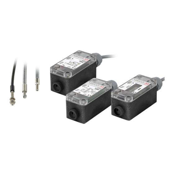
- Page 2 Fiber optics sensors for gap, diameter, edge and presence monitoring MICRO-EPSILON Eltrotec GmbH Manfred-Wörner-Straße 101 73037 Göppingen / Germany Tel. +49 (0) 7161 / 98872-300 Fax +49 (0) 7161 / 98872-303 e-mail eltrotec@micro-epsilon.de www.micro-epsilon.com Certified acc. to DIN EN ISO 9001: 2008...
-
Page 3: Table Of Contents
Contents Safety ............................5 Symbols Used ..............................5 Warnings ................................5 Notes on CE Identification ..........................6 Proper Use ............................... 7 Proper Environment ............................8 Functional Principle, Technical Data ..................9 Short Description ............................. 9 Measuring Principle ............................9 Range / Scanning Range ..........................10 Functions ............................... - Page 4 Operation and Setting ......................23 Operation and Display Elements ........................23 6.1.1 Models CLS-K-10 up to -51 ......................23 6.1.2 Model CLS-K-61..........................24 6.1.3 Models CLS-K-60 /-63 /-65 ......................25 Commissioning .............................. 26 6.2.1 Range Switching S1 ........................26 6.2.2 Adjustment of the Sensibility ......................
-
Page 5: Safety
Safety Safety The handling of the system assumes knowledge of the instruction manual. Symbols Used The following symbols are used in the instruction manual. Indicates a hazardous situation which, if not avoided, may result in minor or moderate injuries. NOTICE Indicates a situation which, if not avoided, may lead to property damage. -
Page 6: Notes On Ce Identification
Products which carry the CE mark satisfy the requirements of the EMC regulation 2004/108/EC ‘Electromag- netic Compatibility’ and the European standards (EN) listed therein. The EC declaration of conformity is kept available according to EC regulation, article 10 by the authorities responsible at MICRO-EPSILON Eltrotec GmbH Manfred-Wörner-Straße 101 73037 Göppingen / Germany... -
Page 7: Proper Use
Safety Proper Use The optical fiber amplifier series CLS-K are optical sensors. These are used with the additional use of fiber optics for optical and non-contact recording of a diameter, edge, gap and the presence of a part during - measuring and inspection tasks - position detection of small parts - position and mounting control on assembly machines and feeding systems - presence monitoring... -
Page 8: Proper Environment
Safety Proper Environment - Protection class: IP 65 - Operating temperature: 0 ... 50 °C (+32 ... +122 °F) - Storage temperature: -25 ... 70 °C (-13 ... +158 °F) - Humidity: 5 - 95 % (non-condensing) - Ambient pressure: Atmospheric pressure - EMC: Acc. -
Page 9: Functional Principle, Technical Data
Functional Principle, Technical Data Functional Principle, Technical Data Short Description The optoCONTROL series CLS-K offers a sensor solution, with which the sensor and the probes are coupled by fiber optics and thus arranged separately. Therefore these optical micrometers are applicable with adverse surrounding conditions like high tempera- tures, small mounting dimensions and bad accessibility in the plants. -
Page 10: Range / Scanning Range
Functional Principle, Technical Data Range / Scanning Range One Way Sensor Fiber strand Range Minimum target size Fiber strand Scanning range ø mm mm (type) (type) ø mm mm (type) ≤ 0.05 ≤ 10 ≤ 0.1 ≤ 30 ≤ 0.1 ≤... - Page 11 Functional Principle, Technical Data 10 V/20 mA 5 V/10 mA α Offset α = Pitch α' 0 V/0 mA 0 V/mA Analog output Analog output »1« »2« Switch S2 in position Switch S2 in position Fig. 2 Functions optoCONTROL CLS-K-61 /-63 optoCONTROL CLS-K Page 11...
-
Page 12: Technical Data
Functional Principle, Technical Data Technical Data 2.5.1 Models CLS-K-10 up to -51 Model CLS-K- Operating voltage VDC 10 - 30 10 - 30 10 - 30 10 - 30 10 - 30 10 - 30 Residual ripple ≤ 10 % Current consumption ~ 50 mA Switching delay... -
Page 13: Models Cls-K-60 Up To -65
Functional Principle, Technical Data Model CLS-K- 50 μA - 50 μA - Switching current 100 mA 100 mA 100 mA 100 mA 100 mA 5 μW - 5 μW - Switching power 60 W 60 W 125 VA 125 VA Switching frequency 4 kHz 4 kHz... - Page 14 Functional Principle, Technical Data Model CLS-K- Switching voltage 30 VDC Switching current 5 - 100 mA Sensitivity Adjustable via 10-level potentiometer P1 Range switching S1 1:100 (Short range : Long range) Switching state LED display red/green Operating mode Light/dark switching output Protection class IP 65 (with fiber optics) Transient-protection polarity,...
-
Page 15: Delivery
Delivery Delivery Unpacking Sensor (amplifier) optoCONTROL CLS-K Power supply cable Instruction manual Optional accessories, e.g. fiber optics, see Chap. Check the delivery for completeness and shipping damage immediately after unpacking. In case of damage or missing parts, please contact the supplier. Storage Storage temperature: -25 up to +70 °C Humidity:... -
Page 16: Mounting
Mounting Mounting No sharped edged or heavy articles may affect on the cables. In any case, avoid definitely kinking of the NOTICE cables. > Damage or destruction of the cable, failure of the sensor 7 (.28) 88 (3.46) 31 (1.22) 60 (2.36) (.55) Connection... -
Page 17: Fiber Optics
Mounting Fiber Optics Various fiber optics are available for the optoCONTROL CLS-K, siehe Kap. 1. It is possible to use an optimal probe even in confined conditions. The fiber optics is inserted into the provided adapter and locked with the cap nut, see Chap. 4.2. The male connector of fiber optics is coded on the amplifier side and must not be plugged in by force! Treat the fiber optics carefully. -
Page 18: Mounting Fiber Optics And Power Supply
Mounting Mounting Fiber Optics and Power Supply Fig. 4 Connection Fig. 5 Model optoCONTROL CLS-K-10 with removed Fig. 6 Connection power fiber optics cover supply Remove the cover of the amplifier, see Fig. 5 and install the amplifier in accordance with the provided mounting holes on the housing. - Page 19 Mounting Power supply cable Amplifier Fiber optics Cap nut Fig. 7 Assembly of the fiber optics on the amplifier Switch on the power supply. After switching on the power supply, the green LED or the red LED lights. optoCONTROL CLS-K Page 19...
-
Page 20: Electrical Connections
Electrical Connections Electrical Connections Pin Assignment Model CLS-K-10 up to -51 5.1.1 CLS-K-10 Pin assignment brown pink +24 VDC green Analog output + yellow Analog output GND gray NPN switching output Fig. 8 Power supply cable, open ends white NPN switching output Fig. -
Page 21: Cls-K-10 /-11
Electrical Connections 5.1.3 CLS-K-10 /-11 Connection type Pink + 24 VDC NPN O.C active dark switching Gray → active light switching → White 5.1.5 CLS-K-20 /-40 Connection type Close relays Open 5.1.7 CLS-K-30 /-50 Connection type Optocoupler output voltage to be switched e.g. 24 VDC Example: PNP for control/consumer load to ground or PIN 5 5.1.9... -
Page 22: Pin Assignment Models Cls-K-60 Up To -65
Electrical Connections Pin Assignment Models CLS-K-60 up to -65 CLS-K-60/-63/-65 CLS-K-61 brown pink 12 - 30 VDC 12 - 30 VDC green Analog output + Current output yellow Analog output GND gray NPN output O.C. NPN output O.C. white NPN output O.C. NPN output O.C. -
Page 23: Operation And Setting
Operation and Setting Operation and Setting Operation and Display Elements 6.1.1 Models CLS-K-10 up to -51 Fig. 12 View on operating and display elements models CLS-K-10 up to -51 S2 Switch for light/dark changeover P2 Potentiometer for timer LED green LED red S1 Range switching P1 Potentiometer sensitivity Fig. -
Page 24: Model Cls-K-61
Operation and Setting 6.1.2 Model CLS-K-61 Fig. 14 View on operating and display elements model CLS-K-61 P3 OFFSET P2 Additional amplification zero offset (Signal spreading) Selector switch analog output Display 1 Basic function 0.1 - 5 VDC 2 Output 0 - 10 VDC LED green P1 Potentiometer sensitivity LED red... -
Page 25: Models Cls-K-60 /-63 /-65
Operation and Setting 6.1.3 Models CLS-K-60 /-63 /-65 Measuring point GND Measuring point U Fig. 16 View on operating and display elements models CLS-K-60 /-63/ -65 P2 Additional amplification P3 OFFSET (signal spreading) zero offset Measuring point GND Measuring point U Selecting switch analog output 1 = Basic function 0 - 10 mA (63) -
Page 26: Commissioning
Operation and Setting P1 potentiometer S1 range switch Near Fig. 18 Settings of the potentiometer P1 and range switch S1 Commissioning After the assembly, set the range switch S1 on Near, see Fig. The warm-up time of the amplifier is approximately 10 min. 6.2.1 Range Switching S1 Near... -
Page 27: Adjustment Of The Sensibility
Operation and Setting 6.2.2 Adjustment of the Sensibility 6.2.2.1 Settings for Reflex Operation Turn the potentiometer P1 (sensitivity) clockwise, until the LED changes from green to red (max. 15 turns), see Fig. Add one turn for the function reserve. In the case of a large scanning range set S1 switch to Far. -
Page 28: Additional Settings With Options
Operation and Setting 6.2.3 Additional Settings with Options - Light or dark switching is selectable with switch S2, see Fig. - Pulse stretching is selectable with the potentiometer P2 by turning clockwise, see Fig. Switch S2 Potentiometer P2 = light = dark Fig. -
Page 29: Special Function For Cls-K-61
Operation and Setting 6.2.4 Special Function for CLS-K-61 The amplifier CLS-K-61 has the following additional special functions: - Zero offset - Signal spreading / Signal amplification The amplifier offers the possibility to spread the signal range which is of special interest for the application to the analog range. - Page 30 Operation and Setting Turn the potentiometer P1 (sensitivity) clockwise, until the LED changes from green to red (max. 15 turns), see Fig. Add one turn for the function reserve. In the case of a large scanning range set S1 switch to Far.
-
Page 31: Special Function For Cls-K-63
Operation and Setting 6.2.5 Special Function for CLS-K-63 6.2.5.1 Setting Reflex Operation / Transmitted Light Mode You will find the description in detail, see Chap. 6.2.2.1, see Chap. 6.2.2.2. Turn potentiometer P1 (sensitivity) clockwise until the LED changes from green to red (Max. 15 turns). -
Page 32: Linearization
Operation and Setting 6.2.5.2 Linearization Based on the basic function the linear part of the function is prepared with P3 “zero point“ and P2 “steepness“. This adjustment requires repetitions as the settings of the potentiometer interfere each other. A multimeter 0 – 10 VDC is connected to the measuring points “GND” and “U”, see Fig. -
Page 33: Instructions For Operation
The warranty period lasts 12 months following the day of shipment. Defective parts, except wear parts, will be repaired or replaced free of charge within this period if you return the device free of cost to MICRO-EPSILON Eltrotec. This warranty does not apply to damage resulting from abuse of the equipment and devices, from forceful handling or installation of the devices or from repair or modifications performed by third parties. -
Page 34: Service, Repair
Service, Repair Service, Repair In the event of a defect on the amplifier or fiber MICRO-EPSILON Eltrotec GmbH optics please send us the effected parts for repair Manfred-Wörner-Straße 101 or exchange. 73037 Göppingen / Germany In the case of faults the cause of which is not clear-... -
Page 35: Appendix
Appendix | Optional Accessories Appendix Optional Accessories Designation Foto Description Article number Different fiber optics see catalog optoCONTROL CLS-K. Example: Reflex fiber optics 10810351 FAR- T-A2.0-2.5-1200-67° FAD- Transmitted fiber 10810490 M-A2.0-2.5-1200-67° optics optoCONTROL CLS-K Seite 35... -
Page 36: A 2 Dimensions Of The Fiber Optics Adapter
Appendix | Dimensions of the Fiber Optics Adapter Dimensions of the Fiber Optics Adapter 34 (1.34) (.31) Cap nut M18x1 (.59) optoCONTROL CLS-K Seite 36... - Page 40 MICRO-EPSILON Eltrotec GmbH X9751308-A011059SWE Manfred-Wörner-Straße 101 · 73037 Göppingen / Germany Tel. +49 (0) 7161 / 98872-300 · Fax +49 (0) 7161 / 98872-303 *X9751308-A01* eltrotec@micro-epsilon.de · www.micro-epsilon.com...
Need help?
Do you have a question about the optoCONTROL CLS-K-10 and is the answer not in the manual?
Questions and answers