
Related Manuals for MICRO-EPSILON capaNCDT 6500


Summary of Contents for MICRO-EPSILON capaNCDT 6500
- Page 1 Instruction Manual capaNCDT 6500 CS005 CSH05FL CSH1.2 CSH3FL CS02 CS08 CSH1.2FL CSH02 CS10 CSH02FL CSE1 CSE2 CSG0.50-CAm2.0 CS05 CSH1 CSH2 CSG1.00-CAm2.0 CSE05 CSH1FL CSH2FL CSH05 CS1HP...
- Page 2 MICRO-EPSILON MESSTECHNIK GmbH & Co. KG Königbacher Straße 15 94496 Ortenburg / Germany Tel. +49/8542/168-0 Fax +49/8542/168-90 e-mail info@micro-epsilon.de www.micro-epsilon.com EtherCAT® is registered trademark and patented technology, licensed by Beckhoff Automation GmbH, Germany.
-
Page 3: Table Of Contents
Averaging Type (AVT) ........................37 6.4.5 Dynamic Noise Rejection ......................... 38 6.4.6 Averaging Number (AVN) ........................ 38 6.4.7 Channel Status (CHS)........................38 6.4.8 Channel Transmit (CHT) ........................38 6.4.9 Mode of Linearization (LIN)......................39 6.4.10 Set Linearization Point (SLP) ......................39 capaNCDT 6500... - Page 4 General ............................63 A 6.2 Define Sensor Measuring Ranges ....................63 A 6.3 Data Format, Word Length ......................64 A 6.4 Set Math Functions ......................... 64 A 6.5 Interpretation of the Measuring Values ..................65 A 6.6 Example ............................65 capaNCDT 6500...
-
Page 5: Safety
EU Directive, article 10, at: MICRO-EPSILON MESSTECHNIK GmbH & Co. KG Königbacher Straße 15 94496 Ortenburg / Germany The measuring system is designed for use in industrial environments and meets the requirements. capaNCDT 6500 Page 5... -
Page 6: Intended Use
- Humidity: 5 - 95 % (non-condensing) - Ambient pressure: atmospheric pressure - Storage temperature: ƒ Sensor cable: -50 ... +200 °C (-58 to +392 °F) (CCmx and CCmx/90) -50 ... +80 °C (-58 to +176 °F) (CCgx and CCgx/90) capaNCDT 6500 Page 6... -
Page 7: Functional Principle, Technical Data
- DL6530: Signal conditioning electronics with integrated preamplifier, distance sensor and controller: 1.4 m (4.6 ft) / 2 m (6 ft) - DL6510: Signal conditioning electronics with external preamplifier, distance sensor and controller: up to 40 m capaNCDT 6500 Page 7... -
Page 8: Sensors
11 mm CSH2 2 mm 17 mm CSH02FL 0.2 mm 7 mm CSH05FL 0.5 mm 7 mm CSH1FL 1 mm 11 mm CSH1,2FL 1.2 mm 11 mm CSH2FL 2 mm 17 mm CSH3FL 3 mm 24 mm capaNCDT 6500 Page 8... -
Page 9: Sensor Cable
It bridges distances of up to 40 m between the preamplifier and the controller. Do not shorten or lengthen these special cables. Model Cable Length Min. bending radius, permanent CA10 10 m CA20 20 m 33 mm CA25 25 m CA30 30 m CA40 40 m capaNCDT 6500 Page 9... -
Page 10: Controller Housing
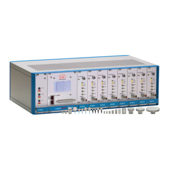
Functional Principle, Technical Data 2.2.5 Controller Housing The capaNCDT 6500 multichannel rack is constructed for up to eight channels, the capaNCDT 6500C multichannel rack is constructed for up to two channels which are all synchronized. Power supply Display board Demodulator Fig. -
Page 11: Dd6500 Display Board With Ethernet Interface
Demodulation, linearization and amplifying of the distance-dependent measuring signal are tasks of the demodulation-unit. The three trim-pots allow a - Linearity - Gain - Zero adjustment of measuring system, see Chap. 5.3, see Chap. 5.4. Fig. 9 Demodulator board DL 6510 capaNCDT 6500 Page 11... -
Page 12: Technical Data
Humidity 5 ... 95 % (non-condensing) Protection class IP 40 (controller and sensors) FSO = Full Scale Output 1) at constant ambient temperature (including temperature and air humidity) 2) Possible to further Controller DT6530 resp. DT6530C capaNCDT 6500 Page 12... -
Page 13: Delivery
Check for completeness and shipping damages immediately after unpacking. In case of damage or missing parts, please contact the manufacturer or supplier. Storage Storage temperature: -10 ° to +75 °C (+14 to 167 °F) Humidity: 5 - 95 % (non-condensing) capaNCDT 6500 Page 13... -
Page 14: Installation And Assembly
Flat sensors are mounted by means of a tap hole for M2 (in case of sensors 0.2 and 0.5 mm) or by a through hole for M2 screws. The sensors can be bolted on top or below. Screwing from above Screwing from bottom capaNCDT 6500 Page 14... -
Page 15: Dimensional Drawing Sensors
(.45 dia.) Dimensions in mm (inches) x = cable length in m ø2.2 (.09 dia.) ø2.2 (.09 dia.) Circumferential clamping possible beginning 3 mm behind the sensor surface. Drawings of other sen- sors are available upon request. capaNCDT 6500 Page 15... - Page 16 ø3 (.22) (.29) (.12 dia.) (.12 dia.) ø2.2 ø2.2 (.09) (.09) Connector side Dimensions in mm (inches) Circumferential clamping possible beginning 3 mm behind the sensor surface. Drawings of other sen- sors are available upon request. capaNCDT 6500 Page 16...
- Page 17 (.09) CSG0.50-CAm2.0 and CSG1.00-CAm2.0 Thickness 0.9 -0.05 (0.04 -0.002 Sensor structures 9.9 (0.39) 1 (0.04) 200 (7.87) 216 (8.5) Sensor structures 4.2 (0.17) (0.11) 3.85 (0.15) (0.18) CSG0.50-CAm2.0 CSG1.00-CAm2.0 Dimensions in mm (inches), not to scale capaNCDT 6500 Page 17...
-
Page 18: Sensor Cable
CCmxC/90 1.4/2.8 or 4.2 m 2.1 mm 0.05 - 0.8 mm 7 mm 15 mm • CCmxB 1.4/2.8 or 4.2 m 2.1 mm 1 ... 10 mm • CCmxB/90 1.4/2.8 or 4.2 m 2.1 mm 1 ... 10 mm capaNCDT 6500 Page 18... -
Page 19: Preamplifier Cp6001 And Cpm6011
Fix the both mounting devices at the preamplifier. Use the screws contained in the delivery. 2.5 x 45° (.1 x 45°) 61.4 (2.40) (.60) (2.90) 84.6 (3.30) Ø4.2 (Ø.16) (.23) (.39) 78.8 (3.10) Fig. 14 Mounting device for preamplifier Dimensions in mm (inches), not to scale. capaNCDT 6500 Page 19... -
Page 20: Preamplifier Cable Cax
6530c (maximum 2 channels) 214 (8) 236 (9) 6530 (maximum 8 channels) 427 (17) 449 (18) Dimensions in mm (inches), not to scale R5.2 8.8 (0.35) 58.6 (2.31) 25,3 (0.99) Fig. 15 Clamping angle Fig. 16 Mounting of clamping angle capaNCDT 6500 Page 20... -
Page 21: Power Supply
Fig. 14 shows two synchronized capaNCDT sensors, measuring against a mill. Due to the unique synchronizing technique of Micro-Epsilon is in most cases a special target earthing not needed. Sensor Controller sync. -
Page 22: Pin Assignment
Use a separate screened cable for the trigger signal. Maximum cable length amounts to 3 m. Recommended conductor cross-section 0.14 mm The EMC regulations, see Chap. 1.3, are only satisfied if these basic conditions have been observed. capaNCDT 6500 Page 22... -
Page 23: Synchronization
Installation and Assembly 4.10 Synchronization Several measuring systems capaNCDT 6500 can simultaneously be used as multi-chan- nel system. With the synchronization of the systems, a mutual influence to the sensors is avoided Plug the synchronize cable SC6000-x (accessory) into the female connector SYNC OUT (synchronization output) at the controller 1. -
Page 24: Operation
If the switch is in position Ethernet, always the Ethernet interface is active independent of the software setting. If the switch is in position ECAT/Auto, then the active interface depends on the software setting. To change the interface it is necessary to restart the controller. capaNCDT 6500 Page 24... -
Page 25: Do6510
+/- 5 V 0-10 V 4-20 mA Out2 +/- 5 V 0-10 V 4-20 mA Out1 +/- 5 V 0-10 V Fig. 25 DO6510 with analog output connectors and rotary switch for voltage and current selection capaNCDT 6500 Page 25... -
Page 26: Dl6530/6510
The potentiometer are ex factory set at the right stop (maximum level). Trimmer Gain: Turn the trim-pot clockwise to increase the slope of the characteristic line. Gain Displacement Trimmer Lin: Turn the trim-pot clockwise to increase the quadratic component. Displacement capaNCDT 6500 Page 26... - Page 27 The limit frequency of the analog output signal can be set with a rotary switch on the board, see Fig. Three positions are possible: Limit frequency fg0 = 8.5 kHz Limit frequency fg1 = 1 kHz Limit frequency fg2 = 20 Hz capaNCDT 6500 Page 27...
-
Page 28: Calibration With Metal Targets
- Potentiometer “Zero“ (Zero-point): right stop - Potentiometer “Lin“ (Linearity): right stop - Potentiometer “Gain“ (Amplification) left stop Carry out the complete calibration up to step 4. Ex factory doubling of measuring range possible by internal matching. capaNCDT 6500 Page 28... -
Page 29: Linearity Adjustment And Calibration With Insulator Targets
Adjustment takes place at defined distances which are prescribed by a reference. A special micrometer calibration device with a non-rotating micrometer spindle (for example MC25 from MICRO-EPSILON) has proved to be particu- larly suitable. Spacer discs are not suitable. - Page 30 Zero point shifting, option of digital linearization, possible by software. Please take details, see Chap. If the measuring values were selected digitally, the analog and digital measuring values disagree after a zero point shifting with the zero-poti. capaNCDT 6500 Page 30...
-
Page 31: Triggering
37-pin Sub-D female connector. To do this, connect all SYNC_OUT outputs to the corresponding Sync_in inputs of the subsequent controller. Use twisted pair for the matching signals. Fig. 31 Synchronization wiring for two controllers capaNCDT 6500 Page 31... -
Page 32: Ethernet Interface
For that purpose, use the web interface or the enclosed runtime version on CD-ROM, see Chap. 6.5, or use your own program. Micro-Epsilon supports the MEDAQLib driver that includes all commands for the capaNCDT 6500. You will find more details on the enclosed CD or on the Internet: www.micro-epsilon.com/en/software “Standard applica- tions >... - Page 33 The controller supports UPnP . If you use an operational system with activated UPnP client e. g. standard with Windows 7, the controller is listed in the explorer as a device automatically. This is helpful, if you do not know the IP address of the controller. capaNCDT 6500 Page 33...
-
Page 34: Data Format Of Measuring Values
Only the measurement value at 10 % of the measurement range is used for the correc- tion of the start of the measurement range. The correction curve for the 2-point-linearization uses data points at 10 % and 90 % of the measurement range. capaNCDT 6500 Page 34... -
Page 35: Commands
Channel numbers are separated by a comma, channel number and a parameter belong- ing to the channel by a colon. Several successive different parameters (for the command STS and VER) are separated by a semicolon. Commands always have to end with <CR> or <CRLF>. capaNCDT 6500 Page 35... -
Page 36: Data Rate (Sra = Set Sample Rate)
6.4.2 Trigger Mode (TRG) If the trigger mode is turned off, the capaNCDT 6500 will send the measurement values without interruption and with the adjusted data rate. There are three possible settings regarding the trigger input, see Chap. 5.5. Irrespective of the trigger mode set, a single measured value per channel can be called up by means of a software command, see Chap. -
Page 37: Get Measured Data (Gmd)
The average value M is derived and output via the selectable number N of successive measuring values. Method Measured values are collected and averaged. The method reduces the data volume because an average value is output only after each n measuring value. capaNCDT 6500 Page 37... -
Page 38: Dynamic Noise Rejection
For example $CHT1,1,0,0,1,0,0,0<CR> Response $CHT1,1,0,0,1,0,0,0OK<CRLF>(Example: Channel 1,2 und 5 are trans- mitted) Request channel transmit Command $CHT?<CR> Response $CHT?1,1,0,0,1,0,0,0 OK<CRLF> Added zeros can be omitted for simplification. For example $CHT1 ,0,0,1,0,0,0,0 can be replaced by $CHT1,0,0,1. capaNCDT 6500 Page 38... -
Page 39: Mode Of Linearization (Lin)
7 = linearization point at 70 % of the measuring range 8 = linearization point at 80 % of the measuring range 9 = linearization point at 90 % of the measuring range 10 = linearization point at 100 % of the measuring range capaNCDT 6500 Page 39... -
Page 40: Get Linearization Point (Glp)
2 = Only the channels to be transmitted are updated 0 = No channels are updated b (Display values): 0 = Non-linearized measuring values are displayed (Default setting) 1 = Linearized measuring values are indicated Request display settings Command $DIS?<CR> Response $DIS?a,bOK<CRLF> capaNCDT 6500 Page 40... -
Page 41: Load Factory Setting (Fde)
If a math function is set on a channel, the channel status changes onto 2. The result of the math function only is output via an Ethernet interface, it is neither shown on the display of the DD6530 nor output as an analog signal. capaNCDT 6500 Page 41... -
Page 42: Get Mathematic Function (Gmf)
Ethernet/EtherCAT is in the position ECAT/Auto. Otherwise always the Ether- net interface is active. The new interface is activated after a restart of the controller. Command $IFCm<CRLF> Example: $IFC1<CRLF> Response $IFCmOK<CRLF> Index m = 0: Ethernet m = 1: EtherCAT Request Command $IFC? Response $IFC?mOK<CRLF> capaNCDT 6500 Page 42... -
Page 43: Query Data Port (Gdp = Get Dataport)
Password = Password of the device. When delivered, no password is assigned. The field can remain empty. 6.4.26 Logout for Web Interface (LGO = Logout) Changes the user level for the web interface on user. Command $LGO<CR> Response $LGOOK<CRLF> capaNCDT 6500 Page 43... -
Page 44: Change Password (Pwd = Password)
- Wrong parameter after command: (ECHO) + $WRONG PARAMETER<CRLF> - Timeout (approximately 15 s after last input) (ECHO) + $TIMEOUT<CRLF> - No channel 1: $ERROR NO CH1<CRLF> - Data rate to high: $ERROR DATARATE TO HIGH<CRLF> - Wrong password: $WRONG PASSWORD<CRLF> capaNCDT 6500 Page 44... -
Page 45: Operation Using Ethernet
IP address: 169.254.168.1. achieve a controller with the serial num- ber “01234567”, type in the address bar on your browser “DT6530_01234567”. Interactive web pages for setting the controller and peripherals are now shown in the web browser. capaNCDT 6500 Page 45... -
Page 46: Access Via Web Interface
Process Data Objects PDO: A PDO telegram is used for real-time transmission of mea- sured values. Individual objects are not addressed. The content of the previously select- ed data is transmitted. The displacement values are transmitted as 32 bit signed integer. capaNCDT 6500 Page 46... -
Page 47: Change Interface
In the case of faults the cause of which is not clearly identifiable, the whole measuring system must be sent back for repair or replacement to MICRO-EPSILON MESSTECHNIK GmbH & Co. KG Königbacher Straße 15 94496 Ortenburg / Germany capaNCDT 6500 Page 47... -
Page 48: Liability For Material Defects
Within this period, defective parts, except for wearing parts, will be repaired or replaced free of charge, if the device is returned to MICRO-EPSILON with shipping costs prepaid. Any damage that is caused by improper handling, the use of force or by repairs or mod- ifications by third parties is not covered by the liability for material defects. -
Page 49: A 1 Optional Accessory
DO6510 Analog output card, 3 channels with 0 ... 10 V, ±5 V or 4 ... 20 mA, digital resolution 16 bit Pre-amplifier cable CA5 5-pin, x = Kabellänge 5 ... 25 m (Standard 5 m) capaNCDT 6500 Page 49... - Page 50 Max. leak rate 1x10e-9 mbar · l s- (.24) Compatible with connector type B Knit line Vacuum feed through triax screw- able Max. leak rate 1x10e-9 mbar · l s- 25 (.98) Compatible with connector type B ø13.50h6 SW11 capaNCDT 6500 Page 50...
-
Page 51: A 2 Services
Fig. 41 Example of measuring range deviation Fig. 42 Example of measuring range deviation in the case of a sensor distance of 10 % of the in the case of a sensor distance of 50 % of the measuring range measuring range capaNCDT 6500 Page 51... -
Page 52: A 4.2 Measurements On Balls And Shafts
Figures give an influence example shown on the sensors CS02 and CS1 in the case of different sensor distanc- es to the target as well as target diameters. As this results from internal simulations and calculations, please request for detailed information. capaNCDT 6500 Page 52... -
Page 53: Ethercat Documentation
- LWR (Logical write, Writing of a logical storage area) - LRW (Logical read write, Reading and writing of a logical storage area) - ARMW (Auto increment physical read multiple write, Reading of a physical area with auto-increment addressing, multiple writing) capaNCDT 6500 Page 53... -
Page 54: A 5.1.3 Addressing And Fmmus
- Sync-Manager-Channel 2: Sync Manager 2 is usually used for process output data. Not used in the sensor. - Sync-Manager-Channel 3: Sync Manager 3 is used for process input data. It contains the Tx PDOs that are specified by the PDO assignment object 0x1C13 (hex.). capaNCDT 6500 Page 54... -
Page 55: A 5.1.5 Ethercat State Machine
The EtherCAT® state machine is implemented in each EtherCAT®. Directly after switch- ing on the capaNCDT 6500, the state machine is in the “Initialization“ state. In this state, the master has access to the DLL information register of the slave hardware. The mail- box is not yet initialized, i.e. -
Page 56: A 5.1.8 Service Data Sdo Service
Number of entries Unsigned8 Vendor ID 0x0000065E Unsigned32 Product code 0x003EDE73 Unsigned32 Revision 0x00010000 Unsigned32 Serial number 0x009A4435 Unsigned32 The article number is deposit in the product code, the serial number of the sensor in serial number. capaNCDT 6500 Page 56... -
Page 57: A 5.2.2 Manufacturer Specific Objects
Measuring values Object 2010h: Controller information 2010 RECORD Controller info Subindices Number of entries Unsigned8 Name DT6530 Visible String ro Serial No xxxxxxxx Unsigned32 Article No xxxxxxx Unsigned32 Option No Unsigned32 Firmware version Visible String ro capaNCDT 6500 Page 57... - Page 58 AVT1 Visible String rw Command Response AVT1OK Visible String ro Any commands can be sent to the controller with the object 2200h, for example, the math functions as these are not defined in the COE objects. capaNCDT 6500 Page 58...
- Page 59 Unsigned8 Counter xxxx Signed32 Channel 1 xxxx Signed32 Channel 2 xxxx Signed32 Channel 3 xxxx Signed32 Channel 4 xxxx Signed32 Channel 5 xxxx Signed32 Channel 6 xxxx Signed32 Channel 7 xxxx Signed32 Channel 8 xxxx Signed32 capaNCDT 6500 Page 59...
-
Page 60: A 5.3 Measurement Data Format
EtherCAT Configuration with the Beckhoff TwinCAT©-Manager For example the Beckhoff TwinCAT Manager can be used as EtherCAT Master. Copy the device description file (EtherCAT®-Slave Information) Micro-Epsilon. xml from the included CD in the directory \\TwinCAT\IO\EtherCAT before the measu- ring device can be configured via EtherCAT®. - Page 61 Appendix | EtherCAT Documentation The current status should be at least PREOP, SAFEOP or OP on the Online side. Example for a complete object directory (subject to change without prior notice). capaNCDT 6500 Page 61...
- Page 62 Appendix | EtherCAT Documentation On the Process data side the PDO allocations can be read from the device. The selected measuring values are transmitted as process data in the status SAFEOP and OP. capaNCDT 6500 Page 62...
-
Page 63: A 6 Thickness Measurement
If no module is on the output channel, the individually set value is overwritten again with 10.000 when the system restarts. If the word length of the data channel is optimally uti- lized and therefore a smaller measuring range is adjusted, this setting must be reset after the restart. capaNCDT 6500 Page 63... -
Page 64: A 6.3 Data Format, Word Length
Enter the offset (distance between the two sensors to one another). In this example here, the offset is 4.000 µm. Give the value 1 as a factor for the measuring channel 1/2. Confirm the input(s) with Submit. capaNCDT 6500 Page 64... -
Page 65: A 6.5 Interpretation Of The Measuring Values
The position tolerance of the target is determined from the offset and measuring range (MR) of sensors. capaNCDT 6500 Page 65... -
Page 66: Capancdt
Sensor 2 Offset 5,200 µm 4,000 µm 4,000 µm 4,000 µm Measuring range 2,000 µm 2,000 µm 2,000 µm 2,000 µm sensors wrong, 0 µm Target thickness 1,600 µm 2,400 µm distance to large (no target) capaNCDT 6500 Page 66... - Page 68 MICRO-EPSILON MESSTECHNIK GmbH & Co. KG X9751294-A111078HDR Königbacher Str. 15 · 94496 Ortenburg / Germany MICRO-EPSILON MESSTECHNIK Tel. +49 (0) 8542 / 168-0 · Fax +49 (0) 8542 / 168-90 *X9751294-A11* info@micro-epsilon.de · www.micro-epsilon.com...
Need help?
Do you have a question about the capaNCDT 6500 and is the answer not in the manual?
Questions and answers