
Subscribe to Our Youtube Channel
Related Manuals for Rockwell Automation VICPAS PanelView Plus Compact 400


Summary of Contents for Rockwell Automation VICPAS PanelView Plus Compact 400
- Page 1 PanelView Plus Compact Terminals User Manual 2711PC-K4M20D, Catalog Numbers 2711PC-B4C20D, 2711PC-T6M20D, 2711PC- T6C20D, 2711PC-T10C4D1...
- Page 2 BURN HAZARD surfaces may reach dangerous temperatures. Allen-Bradley, PanelView Plus, PanelView Plus Compact, FactoryTalk View, FactoryTalk View ME, FactoryTalk View Studio, FactoryTalk ViewPoint, RSLinx Enterprise, Rockwell Automation, and TechConnect are trademarks of Rockwell Automation, Inc. Trademarks not belonging to Rockwell Automation are property of their respective companies.
-
Page 3: Table Of Contents
Table of Contents Preface Intended Audience ....... . 7 Parts List ........7 Additional Resources. - Page 4 Table of Contents Configuring the Touch Screen ..... . . 56 Configuring Print Options ......58 Configuring Startup Options .
- Page 5 Table of Contents Chapter 8 Troubleshooting Chapter Objectives ......105 Status Indicators ....... . 105 Isolating the Problem .
- Page 6 Table of Contents Publication 2711PC-UM001A-EN-P - March 2009...
-
Page 7: Intended Audience
PanelView Plus Devices Technical Data, for PanelView Plus terminals. publication 2711P-TD001 You can view or download publications at http://literature.rockwellautomation.com. To order paper copies of technical documentation, contact your local Rockwell Automation distributor or sales representative. 7Publication 2711PC-UM001A-EN-P - March 2009... - Page 8 Preface Publication 2711PC-UM001A-EN-P - March 2009...
-
Page 9: Chapter 1 Chapter Objectives
Chapter Overview Chapter Objectives This chapter covers these topics: • Product description • Catalog number explanation • Software support • Terminal configurations • Display modules • Accessories Product Overview The PanelView Plus Compact terminals are similar to some PanelView Plus terminal configurations but with limited hardware and software functions. -
Page 10: Software Support
Chapter 1 Overview Software Support Each terminal is preloaded with FactoryTalk View Machine Edition runtime and configuration software that does not require activation. Applications for the compact terminals are created using FactoryTalk View Studio software. Software Requirements Version FactoryTalk View Studio 5.1 or later 5.20 or later RSLinx Enterprise... -
Page 11: Displays
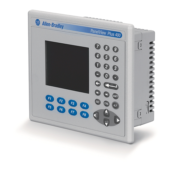
Overview Chapter 1 Displays The terminal configurations provide monochrome or color displays with keypad, touch, or keypad/touch input. Keypad Description of 400 Terminals Keys Description F1 through F8 Programmable keys that initiate functions on terminal display. Numeric Keypad 0…9, ., -, Backspace, Enter, Left and Right Tab keys, Shift keys Navigation Keys Use the arrow keys for navigation. - Page 12 Chapter 1 Overview Replacement Bezels Cat. No. Description 2711P-RBT10 Replacement bezel for 1000 touch terminal Protective Antiglare Overlays Cat. No. Description 2711P-RGK4 Antiglare overlay (3) for PanelView Plus 400 keypad terminal 2711P-RGB4 Antiglare overlay (3) for PanelView Plus 400 color keypad/touch terminal 2711P-RGT6 Antiglare overlay (3) for PanelView Plus 600 touch terminal 2711P-RGT6...
-
Page 13: Chapter 2 Chapter Objectives
Chapter Installing the Terminal Chapter Objectives This chapter provides pre-installation information and procedures on how to install the terminals. • Hazardous locations • Environment and enclosure • Required tools • Clearances • Panel cutout dimensions • Mount the 400 or 600 terminal in a panel •... - Page 14 Chapter 2 Installing the Terminal USB Ports The PanelView Plus Compact terminals contain universal serial bus (USB) ports that comply with hazardous location environments. This section details the field-wiring compliance requirements and is provided in accordance with the National Electrical Code, article 500. PanelView Plus Compact Terminals Control Drawing Associated Nonincendive Field Wiring Apparatus Nonincendive Field...
- Page 15 Installing the Terminal Chapter 2 Application Information Per the National Electrical Code the circuit parameters of nonincendive field wiring apparatus for use in hazardous locations shall be coordinated with the associated nonincendive field wiring apparatus such that their combination remains nonincendive. The PanelView Plus terminal and the USB peripheral device shall be treated in this manner.
-
Page 16: Environment And Enclosure
Chapter 2 Installing the Terminal Environment and Enclosure This equipment is intended for use in a Pollution Degree 2 ATTENTION industrial environment, in overvoltage Category II applications (as defined in IEC 60664-1), at altitudes up to 2000 m (6561 ft) without derating. -
Page 17: Required Tools
Installing the Terminal Chapter 2 Required Tools These tools are required for panel installation: • Panel cutout tools • Small, slotted screwdriver • Torque wrench (lb•in) for tightening the mounting clips on the 1000 terminal Clearances Allow adequate clearance around the terminal, inside the enclosure, for adequate ventilation. -
Page 18: Mount The 400 Or 600 Terminal In A Panel
Chapter 2 Installing the Terminal Mount the 400 or 600 Mounting levers secure the terminal to the panel. The number of levers you use (4 or 6) varies by terminal type. Terminal in a Panel Disconnect all electrical power from the panel before making ATTENTION the panel cutout. - Page 19 Installing the Terminal Chapter 2 Slide each lever until the flat side of the lever touches the surface of the panel. Mounting Levers Mounting Slots Flat Side of Lever 5. When all levers are in place, slide each lever an additional notch or two until you hear a click.
-
Page 20: Mount The 1000 Terminal In A Panel
Chapter 2 Installing the Terminal Mount the 1000 Terminal in Mounting clips secure the terminal to the panel. a Panel Disconnect all electrical power from the panel before making ATTENTION the panel cutout. Make sure the area around the panel cutout is clear. Take precautions so metal cuttings do not enter any components already installed in the panel. - Page 21 Installing the Terminal Chapter 2 4. Slide the ends of the mounting clips into the slots on terminal. Mounting Clip Mounting Clip Slot 5. Tighten the mounting clip screws by hand until the gasket seal contacts the mounting surface uniformly. 6.
-
Page 22: Product Dimensions
Chapter 2 Installing the Terminal Product Dimensions Product dimensions for each terminal are in mm (in.). PanelView Plus 400 Keypad or Keypad/Touch Dimensions (2.35) (3.54) (6.0) 71 (2.81) 154 (6.08) 185 (7.28) PanelView Plus Compact 600 Touch Dimensions 68 (2.68) 152 (6.0) 98 (3.86) 71 (2.81) -
Page 23: Chapter 3 Chapter Objectives
Chapter Connecting Power Chapter Objectives This chapter covers wiring and safety guidelines, and provides procedures to: • remove and install the power terminal block. • connect DC power. • reset the terminal. Wiring and Safety Use publication NFPA 70E Electrical Safety Requirements for Employee Workplaces, IEC 60364 Electrical Installations in Buildings, Guidelines or other applicable wiring safety requirements for the country of... -
Page 24: Removing And Installing The Power Terminal Block
Chapter 3 Connecting Power Removing and Installing the The terminals are shipped with the power terminal block installed. You can remove the terminal block for ease of installation, wiring, and Power Terminal Block maintenance. Explosion Hazard WARNING Substitution of components may impair suitability for hazardous locations. - Page 25 Connecting Power Chapter 3 Follow these steps to replace the terminal block. 1. Press the terminal block base in first with block leaning outward. 2. Gently push the top of the terminal block back to the vertical position to snap in locking tab. PanelView Plus Compact 1000 Terminals Follow these steps to remove the terminal block.
-
Page 26: Connecting Power
Chapter 3 Connecting Power Connecting Power The PanelView Plus Compact terminals have an integrated, 24V DC power supply. See Appendix Specifications for power ratings. The power supply is internally protected against reverse polarity of the DC+ and DC- connections. Connecting DC+ or DC- to the earth terminal may damage the device. - Page 27 Connecting Power Chapter 3 Earth/Ground Connection You must connect the earth/ground terminal to a low-impedance earth/ground. • The 1000 terminals have the earth/ground connection on the rear of the display module. • The 400 and 600 terminals have the functional earth/ground connection on the power input terminal block.
- Page 28 Chapter 3 Connecting Power Connect DC Power Explosion Hazard - Do not disconnect equipment unless power WARNING has been switched off and area is known to be nonhazardous. Disconnect all power before installing or replacing components. Failure to disconnect power may result in electrical shock or damage to the terminal.
-
Page 29: Resetting The Terminals
Connecting Power Chapter 3 Resetting the Terminals Use the reset switch to restart a terminal without having to disconnect and reapply power. After a reset, the terminal performs a series of startup tests and then either: • runs the .MER application loaded in the terminal. •... - Page 30 Chapter 3 Connecting Power Publication 2711PC-UM001A-EN-P - March 2009...
-
Page 31: Chapter 4 Chapter Objectives
Chapter Configuring the Terminal Chapter Objectives This chapter shows how to use the Configuration mode of your terminal to: • perform data entry and navigation. • load an application. • run an application. • modify application settings. • modify terminal settings. Accessing Configuration Your terminal has onboard software, FactoryTalk View ME Station, to perform and configure terminal operations. - Page 32 Chapter 4 Configuring the Terminal Configuration Mode Name of application that is currently loaded. Only appears if application is loaded. Terminal Operation Description Load Application (F1) Opens another screen where you can select an application to load. Once loaded, the application name will appear under Current Application.
- Page 33 Configuring the Terminal Chapter 4 Navigation Buttons Screen buttons are used for data entry and navigation. • On touch-screen terminals, tap the button with your finger or stylus. • On keypad terminals, select the function key listed on the button, or in some cases, the corresponding key on the keypad. •...
- Page 34 Chapter 4 Configuring the Terminal Enter or Edit Data Many screens have buttons that access fields where you must enter or edit data. When you press the button or function key, the input panel opens ready for you to enter data. If a field is restricted to a numeric value, only the 0…9 keys will be enabled.
-
Page 35: Loading An Application
Configuring the Terminal Chapter 4 Loading an Application You can load a FactoryTalk View ME .MER application from internal CompactFlash in the terminal or an external CompactFlash card. List of .MER applications stored in the CompactFlash of Moves the terminal. highlight up Moves highlight down... -
Page 36: Running An Application
Chapter 4 Configuring the Terminal Running an Application After loading an .MER application, you can run the application. To load an application, select the Run Application button on the main screen. Log files are generated by the application. To delete the log files before running an application, select the Delete Log Files Before Running button on the main screen. -
Page 37: Configuring Communication
Configuring the Terminal Chapter 4 Follow these steps to access terminal settings and select a function. 1. Select Terminal Settings from the main screen. Diagnostics Setup Display File Management Moves highlight up. Font Linking Input Devices Networks and Communications Print Setup Startup Options System Event Log Moves highlight... - Page 38 Chapter 4 Configuring the Terminal Configure Communication Properties Follow these steps to configure driver settings for the communication protocol used by your application. 1. Select Terminal Settings>Networks and Communications>RSLinx Enterprise Communications. You see a tree view of installed communication cards and network configurations.
- Page 39 Configuring the Terminal Chapter 4 Serial Properties Field Description Valid Values Device The serial device your terminal is connected PLC_CH0 SLC_CH0 KFC15 AC_CH0 Error Check Type of error checking used. Error checking is BCC, CRC automatically configured if Use Auto Config is set to Yes.
- Page 40 Chapter 4 Configuring the Terminal Configure the Controller Address Follow these steps to edit the device address of the logic controller. 1. From the RSLinx Configuration screen, select a device node. 2. Press the Edit Device button to view the device name and current address of the logic controller.
-
Page 41: Configuring Network Information
Configuring the Terminal Chapter 4 Configuring Network You can configure network information for your terminal. • Device name to identify terminal on network Information • IP address of terminal on network • Username and password to access network resources Define a Device Name for the Terminal You can configure a device name and description to identify your your terminal on the network. - Page 42 Chapter 4 Configuring the Terminal Define an Ethernet IP Address Some networks automatically assign IP addresses to Ethernet devices if DHCP is enabled. If DHCP is not enabled, you can manually enter an IP address for the terminal. Follow these steps to view or enter an IP address for your terminal. 1.
- Page 43 Configuring the Terminal Chapter 4 Field Description Valid Values Use DHCP Enables or disables Dynamic Host Yes (default) Configuration Protocol (DHCP) settings. DHCP automatically allocates network devices and configurations to newly attached devices on the network. If DHCP is set to Yes, the terminal is automatically assigned an IP address, Subnet Mask, and Gateway.
- Page 44 Chapter 4 Configuring the Terminal Define Name Server Addresses You can define name server addresses for the EtherNet/IP network adapter. These addresses are automatically assigned if DHCP is enabled for the network adapter. Follow these steps to define name server address. 1.
-
Page 45: Configuring Diagnostics
Configuring the Terminal Chapter 4 Authorize Terminal to Access Network Resources The terminal can access network resources with proper identification. A user name, password, and domain must be provided by your network administrator. 1. Select Terminal Settings>Networks and Communications>Network Connections>Network Identification. 2. - Page 46 Chapter 4 Configuring the Terminal Remote Log Destination The Remote Log Destination forwards messages that it receives to a Windows 2000/XP computer running diagnostics. The location is determined by the IP address and port number. Field Description Valid Values Address Address of the remote Windows xxx.xxx.xxx.xxx 2000/XP computer.
-
Page 47: Managing Files On The Terminal
Configuring the Terminal Chapter 4 Managing Files on the The terminal provides operations for managing files that are stored on the terminal. Terminal • Delete application .MER files, font files, or log files that reside in a storage location on the terminal. •... - Page 48 Chapter 4 Configuring the Terminal Delete Log Files from Terminal You can delete log files, alarm history files, and alarm status files from the System Default location on the terminal. 1. Select Terminal Settings>File Management>Delete Files>Delete Log Files. You are asked to confirm the deletion of the files. 2.
- Page 49 Configuring the Terminal Chapter 4 5. Press the Destination button to choose the storage location where you want to copy the application or font file. The destination must be different than the source location. • Internal Storage - the internal CompactFlash in the terminal. •...
-
Page 50: Modifying Display Settings
Chapter 4 Configuring the Terminal Modifying Display Settings You can access and modify these display settings for your terminal: • View display temperature • Adjust display contrast • Adjust display intensity • Configure the screen saver • Enable or disable the screen cursor View the Display Temperature To view the current temperature of the display, select Terminal Settings>Display>Display Temperature. - Page 51 Configuring the Terminal Chapter 4 Adjust the Display Contrast You can view or modify the display contrast for 400 and 600 grayscale terminals. Displays are shipped with the contrast level set at 50%, which is the optimum setting. 1. Select Terminal Settings>Display>Display Contrast. 2.
- Page 52 Chapter 4 Configuring the Terminal Configure the Screen Saver The terminal screen saver activates after an idle period using a specific intensity. You can adjust the idle timeout and intensity, disable the screen saver, and enable or disable the screen saver bitmap. 1.
-
Page 53: Font Linking
Configuring the Terminal Chapter 4 Enable or Disable the Screen Cursor The terminal has a screen cursor that you can enable or disable. 1. Select Terminal Settings>Display>Cursor. 2. Press the Enable Cursor button to enable or disable the cursor. 3. Press OK to exit and return to Terminal Settings. Font Linking Font linking lets you run a translated application on the terminal by linking a font file to the base font, for example, linking a Chinese font... -
Page 54: Configuring The Keypad, Keyboard, Or Mouse
Chapter 4 Configuring the Terminal Configuring the Keypad, You can configure input devices used with your terminal, including the keyboard, keypad, mouse, and attached keyboard. Keyboard, or Mouse Configure Keyboard Settings You can adjust settings for the keys on the terminal keypad or for keys on an attached keyboard. - Page 55 Configuring the Terminal Chapter 4 Configure Keypad Settings for the Terminal You can restrict multiple or simultaneous key presses on the keypad of your terminal. 1. Select Terminal Settings>Input Devices>Keypad. 2. Press the Single Key Mode button to select a key option. •...
-
Page 56: Configuring The Touch Screen
Chapter 4 Configuring the Terminal Configuring the Touch You can configure these operations for terminals with a touch screen: • Calibrate the touch screen Screen • Enable or disable Cursor • Set the double-tap sensitivity Calibrate the Touch-screen Use a plastic stylus device with a minimum tip radius of 1.3 mm IMPORTANT (0.051 in.) to prevent damage to the touch screen. - Page 57 Configuring the Terminal Chapter 4 Enable or Disable the Cursor on Touch Screens You can enable or disable the cursor on terminals with a touch screen. Disabling the cursor will not disable the mouse. 1. Select Terminal Settings>Input Devices>Touch Screen>Cursor. 2.
-
Page 58: Configuring Print Options
Chapter 4 Configuring the Terminal Configuring Print Options You can configure settings for printing displays, alarm messages, or diagnostic messages from FactoryTalk View ME .MER applications. The general setup for printing displays and messages is the same, however, the advanced settings are different. 1. - Page 59 Configuring the Terminal Chapter 4 • The advanced settings for printing diagnostic and alarm messages determines when to print messages that are sent to the network or USB port. Print Messages After Default Value Example Specified number of messages 60 messages When the queue has 60 messages, the messages are printed regardless of how long they have been in the queue.
-
Page 60: Configuring Startup Options
Chapter 4 Configuring the Terminal Configuring Startup Options The action the terminal takes on startup depends on how you configure the startup options. You can: • disable FactoryTalk View ME Station software. • go to FactoryTalk View Configure mode. • run the current application. Disable FactoryTalk View ME Station Software on Startup Follow these steps to disable FactoryTalk View Station software on startup. - Page 61 Configuring the Terminal Chapter 4 Enter Configuration Mode on Startup Follow these steps to enter Configuration mode on startup. 1. Select Terminal Settings>Startup Options>FactoryTalk View ME Station Startup. 2. Press the On Startup button to select Go to Configuration Mode. 3.
- Page 62 Chapter 4 Configuring the Terminal Run the Loaded Application on Startup Follow these steps to run the loaded application on startup. 1. Select Terminal Settings>Startup Options>FactoryTalk View ME Station Startup. 2. Press the On Startup button to select Run Current Application. If an application is not loaded, the options are disabled.
-
Page 63: Configuring Startup Tests
Configuring the Terminal Chapter 4 Configuring Startup Tests The terminal can run extended tests on startup. You can select which test to run and also specify test settings on startup. Select Tests to Run on Startup Follows these steps to select tests to run on startup. 1. - Page 64 Chapter 4 Configuring the Terminal Configure Startup Test Settings Follow these steps to specify how many times to run the selected tests on startup and to enable extended diagnostics. Enabling extended diagnostics and setting a high repeat count IMPORTANT will increase the time it takes the terminal to reboot. The tests will run each time you reset or cycle power to the terminal until you disable extended diagnostics.
-
Page 65: Clearing The System Event Log
Configuring the Terminal Chapter 4 Clearing the System Event The System Event Log screen displays a list of system events logged by the terminal. Follow these steps to clear all or some of the events from the system event log. 1. -
Page 66: Displaying Terminal Information
Chapter 4 Configuring the Terminal Displaying Terminal You can view these details for your terminal: • Total power on time Information • Processor temperature • Battery voltage and battery state • Amount of memory on terminal Follow these steps to display terminal information. 1. - Page 67 Configuring the Terminal Chapter 4 2. Press the Memory Allocation button to view or adjust the: • amount of allocated storage or program memory. • amount of storage or program memory in use. 3. Press the Up or Down button to increase or decrease the allocation of storage or program memory.
-
Page 68: Displaying
Chapter 4 Configuring the Terminal Displaying You can display the firmware number of FactoryTalk View ME Station software and the Rockwell Automation technical support number. FactoryTalk View ME Station Information 1. Select Terminal Settings>System>Information>About FactoryTalk View ME Station. x.xx.xx.x 2. Press the Technical Support button, if desired. -
Page 69: Modifying The Date, Time, Or Time Zone
Configuring the Terminal Chapter 4 Modifying the Date, Time, You can adjust the date and time for terminal operations, or change the time zone. or Time Zone Change the Date Follow these steps to change the date on the terminal. 1. - Page 70 Chapter 4 Configuring the Terminal Change the Time Zone You can modify the current time zone on the terminal. Time zones are installed as a part of the operating system. When changing the time zone, the current time and date are adjusted to match the time zone. Follow these steps to change the time zone.
-
Page 71: Modifying Regional Settings
Configuring the Terminal Chapter 4 Modifying Regional You can adjust regional settings for a specific language installed on the terminal, including the date, time and numeric formats. Settings To access regional settings for a language, select Terminal Settings>Time/Date/Regional Settings>Regional Settings. The current language appears at the bottom of the Regional Settings screen. - Page 72 Chapter 4 Configuring the Terminal Change the Time Format You can change the time format for the selected language. 1. Select Terminal Settings>Time/Date/Regional Settings>Regional Settings>Time Format. The current time is shown in the currently selected format. 2. Press the appropriate buttons to adjust the formats. Field Description Example...
- Page 73 Configuring the Terminal Chapter 4 Change the Short Date Format You can change the short date format for the selected language. 1. Select Terminal Settings>Time/Date/Regional Settings>Regional Settings>Short Date Format. The current date is shown in the selected, short date format. Field Short Date Formats Example...
- Page 74 Chapter 4 Configuring the Terminal Change the Long Date Format You can change the long date format used by the selected language. 1. Select Terminal Settings>Time/Date/Regional Settings>Regional Settings>Long Date Format. The current date is shown in the selected long date format. 2.
-
Page 75: Chapter 5 Chapter Objectives
Chapter Installing and Replacing Components Chapter Objectives This chapter shows how to install or replace specific components of the terminals. • Battery • Backlight • External CompactFlash card • Product ID label • Display module bezel Required Tools These tools are required to install and replace components: •... -
Page 76: Replacing The Battery
Chapter 5 Installing and Replacing Components Replacing the Battery The lithium battery in the terminals is used by the real-time clock and static RAM; it is not used for application backup or retention. The clock module has a life expectancy of two years without power. The replacement battery is catalog number 2711P-RY2032. - Page 77 Installing and Replacing Components Chapter 5 4. Carefully lift the logic module away from the terminal and flip over to expose the circuit board. Wear a properly grounded ESD wristband before ATTENTION touching any of the electronic components in the logic module.
- Page 78 Chapter 5 Installing and Replacing Components Battery Removal for the 400 and 600 Terminals The lithium battery in the 400 and 600 is non-replaceable and should be removed only at the end of product life. This product contains a hermetically sealed lithium battery which is permanently connected and should be removed only by trained professionals.
-
Page 79: Replacing The Backlight
Installing and Replacing Components Chapter 5 Replacing the Backlight This section shows how to replace the backlight in the 1000 terminal. The replacement backlight is catalog number 2711P-RL10C2. The backlight contains mercury. At the end of its life, the IMPORTANT backlight should be collected separately from unsorted municipal waste. - Page 80 Chapter 5 Installing and Replacing Components 6. Press the retaining tab that secures the backlight and then pull out the backlight. Backlight Retaining Tab 7. Insert the new backlight. Backlight 8. Attach the LCD display connector to the circuit board. Refer to step 4.
-
Page 81: Using An External Compactflash Card
Installing and Replacing Components Chapter 5 Using an External All of the terminals have a CompactFlash card slot that supports Type 1 CompactFlash cards. These cards are available in different CompactFlash Card memory sizes. CompactFlash Card Slot Insert a CompactFlash Card Insert the card in the CompactFlash card slot of the terminal until firmly seated. -
Page 82: Removing The Product Id Label
Chapter 5 Installing and Replacing Components Remove a CompactFlash Card Press the Eject button on the logic module. When the button pops out, press it again to release the card. The location of the button varies depending on the series of the logic module. The 400 and 600 terminals do not have an eject button. -
Page 83: Replacing The Bezel
Installing and Replacing Components Chapter 5 Replacing the Bezel The 1000 terminal has a touch screen that can only be replaced with the same touch screen. You do not have to remove the logic module before removing the display module bezel. Follow these steps to remove the display module bezel on the 1000 terminal. - Page 84 Chapter 5 Installing and Replacing Components 6. Remove the sealing gasket. 7. Lift the back of the display module away from the bezel. Work on a clean, flat, stable surface to protect the display from debris, scratches and damage. Display Module Bezel 8.
-
Page 85: Cleaning The Display Window
Installing and Replacing Components Chapter 5 Follow these steps to replace the display module bezel. 1. Make sure the bezel is free of lint and marks. 2. Attach the touch screen connector. 3. Place the back of the display module over the bezel. Be careful not to pinch any of the cables. - Page 86 Chapter 5 Installing and Replacing Components Publication 2711PC-UM001A-EN-P - March 2009...
-
Page 87: Chapter 6 Chapter Objectives
Chapter Terminal Connections Chapter Objectives This chapter provides network and device connections for the terminals. • Runtime communication cables • Communication port isolation • USB ports • Serial connections on base unit • Ethernet (onboard communication) Cables for Runtime The tables provide a summary of terminal connections to controllers and network interface modules for runtime communication. -
Page 88: Communication Port Isolation
Chapter 6 Terminal Connections PanelView Plus Compact to Logix Controllers Cables: PanelView Plus Compact to Logix Controllers ControlLogix CompactLogix PanelView Plus Compact Protocol CH0 (9-pin RS-232) CH0 (9-pin RS-232) 400, 600, 1000 Comm Port (DF1) (DF1 or DH-485) 2711-NC13 (5 m/16 ft) RS-232 (DF1) Comm port (9-pin) 2711-NC14 (10 m/32 ft) 2706-NC13 (3 m/10 ft) -
Page 89: Usb Ports
Terminal Connections Chapter 6 USB Ports The 1000 terminals have two USB ports. The 400 and 600 terminals have one USB port. The terminals support standard USB keyboard and mouse devices (HID devices) with native device drivers. They also support some USB printers that have Printer Control Language (PCL) capabilities. -
Page 90: Serial Connections
Chapter 6 Terminal Connections Serial Connections All compact terminals have a serial RS-232 port that supports: • DH-485 communication through a serial connection. • DF1 full duplex communication with controllers using direct connections or modem connections. • third-party point-to-point communication. •... - Page 91 Terminal Connections Chapter 6 Modem Connection Wire or radio modem communication is possible between the terminal and controller. Each modem must support full duplex communication. Refer to your modem user manual for details on settings and configuration. PanelView Plus Compact Terminal Optical Isolator Controller DF1 Port...
- Page 92 Chapter 6 Terminal Connections Computer Connections The RS-232 serial port on the base-configured unit of the terminals supports: • application uploads/downloads using a direct connection. • printing. PanelView Plus Compact Terminals Computer Available Cables Cat. No. 2711-NC13, 5 m (16.4 ft) 25-pin to 9-pin Cat.
-
Page 93: Ethernet Connections
Terminal Connections Chapter 6 Ethernet Connections The Ethernet port on the PanelView terminals supports: • EtherNet/IP communication. • third-party Ethernet communication. • network connections. • application uploads/downloads. • printing. Ethernet Connector The terminals have an RJ45, 10/100 Base-T connector for EtherNet/IP or Ethernet TCP/IP network communication. - Page 94 Chapter 6 Terminal Connections Ethernet Cable For PanelView Plus Compact 1000 terminals use Belden 7921A shielded Ethernet Category 5e cable according to TIA 568-B.1 and RJ45 connector according to IEC 60603-7 for compliance with the European Union 89/336/EEC EMC Directive. The maximum cable length between the terminal’s Ethernet port and a 10/100 Base-T port on an Ethernet hub (without repeaters or fiber) is 100 m (328 ft).
-
Page 95: Chapter 7 Chapter Objectives
Chapter Upgrading Firmware Chapter Objectives This chapter shows how to upgrade firmware in a PanelView Plus Compact terminal using the Firmware Upgrade Wizard. Transferring Applications You can transfer applications using a CompactFlash card or a computer. • To copy or load applications on the terminal from terminal configuration mode using a CompactFlash card, refer to Loading an Application on page 35. -
Page 96: Upgrading Firmware With A Compactflash Card
Chapter 7 Upgrading Firmware Upgrading Firmware with a Upgrading terminal firmware using a CompactFlash card is a two-step process. First, you create a firmware upgrade card with the necessary CompactFlash Card firmware files. Second, you load the card in the target terminal to upgrade the firmware. - Page 97 Upgrading Firmware Chapter 7 3. From the Firmware source folder list, browse to the location of the firmware files. The default location is shown. 4. From the Upgrade firmware version list, select the firmware version for the upgrade, then press Next. 5.
- Page 98 Chapter 7 Upgrading Firmware 6. Click Finish to copy the firmware source files to the location specified in step 2. If the files were created in a folder on a local hard drive, copy the files to the root directory of the CompactFlash card. Upgrade Firmware in Terminal with Firmware Upgrade Card Follow these steps to upgrade the terminal firmware from a CompactFlash card.
- Page 99 Upgrading Firmware Chapter 7 A dialog box shows the progress of the upgrade. 4. After the terminal resets twice, the new firmware is installed. • On touch-screen terminals, you must calibrate the touch screen after the first terminal reset by selecting pointers in all four corners of the screen and pressing the middle of the screen when prompted.
-
Page 100: Upgrading Firmware Over A Network Connection
Chapter 7 Upgrading Firmware Upgrading Firmware over a You can upgrade firmware in a terminal that is connected to a computer using a direct serial connection or network connection. Network Connection • Serial connection requires a RAS connection to be set up on computer. - Page 101 Upgrading Firmware Chapter 7 A dialog box reminds you to back up all .mer and user files before upgrading the terminal. 3. Click Yes if you want to continue with the upgrade. 4. Select Network connection and click Next. Use the Ethernet and Serial connections only if the firmware upgrade is unsuccessful.
- Page 102 Chapter 7 Upgrading Firmware 6. From the Firmware source folder text box, select the location of the firmware files. The default location is C:\Program Files\Rockwell Software\RSView Enterprise\FUPs. 7. From the Upgrade firmware version list, select the firmware for the upgrade, then click Next. 8.
- Page 103 Upgrading Firmware Chapter 7 9. Click Finish to start the upgrade. 10. Click Yes to continue the upgrade process. If the terminal was properly prepared for the upgrade, no applications should be running. Firmware files are downloaded to the terminal. This may take several minutes to 15 minutes.
- Page 104 Chapter 7 Upgrading Firmware 12. After the terminal resets twice, the new firmware is installed. • On touch-screen terminals, you must calibrate the touch screen after the first terminal reset by selecting pointers in all four corners of the screen and pressing the middle of the screen when prompted.
-
Page 105: Chapter Objectives
Chapter Troubleshooting Chapter Objectives This chapter provides information on how to isolate and correct common operating problems with system components. • Status indicators • Isolate the problem • Startup error messages • Startup information messages • Startup sequence • Check terminal components •... -
Page 106: Isolating The Problem
Chapter 8 Troubleshooting Isolating the Problem This section provides general troubleshooting information to assist you when trying to isolate problems. Check for Adequate Power A terminal that does not receive adequate power could result in unpredictable behavior. Refer to Appendix A, Specifications, for power requirements. - Page 107 Troubleshooting Chapter 8 Check Voltages and Temperatures To check the battery voltage and processor temperature, enter Configuration mode and select Terminal Settings>System Information>Terminal Information. • The battery voltage must be at least 2.75V DC. Replace the battery if the voltage is less than 2.75V DC. •...
-
Page 108: Startup Information Messages
Chapter 8 Troubleshooting Startup Information Startup messages display in a specific sequence on the terminal during startup and typically display for a few seconds. These messages Messages indicate the startup sequence of the terminal, but do not require that you perform any action. Message # Displayed Message Description... -
Page 109: Startup Sequence
Troubleshooting Chapter 8 Startup Sequence This flow chart provides a sequence of startup operations for the terminal and shows system information messages that are displayed on the terminal. Power On Display copyright message, bootcode versions and Testing... message Initialize Video - Display 37 Video Initialized (1000 only) Perform Power On Self Test Display 30 Watchdog Test Display 1 RAM Test... -
Page 110: Startup Error Messages
Chapter 8 Troubleshooting Startup Error Messages When an error occurs, the terminal displays the error number with a text message. The word ERROR! appears under this line in different languages. # Displayed Message ERROR! FEHLER! ERREUR! ERRORE! Error # Displayed Message Description Recommended Corrective Action RAM Test... -
Page 111: Checking Terminal Components
Troubleshooting Chapter 8 Checking Terminal This section provides tips on how to isolate problems with the terminal display, touch screen, keypad, attached keyboard, or mouse. Components Resolve Problems with Display Symptom Recommended Action Page The display is dim or unreadable. Check the brightness setting on color displays. - Page 112 Chapter 8 Troubleshooting Resolve Problems with Keypad Problem Recommended Action Page The hold-off delay may be longer than Check keypad settings. Enter Configuration mode and select Terminal expected or multiple key presses might be Settings>Input Devices>Keypad. inhibited by multi-key lockout. Home, End, Page Up or Page Down are not supported when single key or multi-key lockout is enabled.
- Page 113 Troubleshooting Chapter 8 Resolve Problems With Keyboard Problem Recommended Action Page The keyboard does not work. Check the USB cable and connector. Detach and reattach the keyboard. Verify a good connection. Cycle power to the terminal. Keyboard keys may not be enabled as Check for enabled Alt-Ctrl keys.
-
Page 114: Ethernet Connection
Chapter 8 Troubleshooting Ethernet Connection This section provides tips on how to isolate Ethernet problems. • Check the status indicators at the Ethernet connector. Green indicates a communication link and should be ON. Amber indicates data activity and should be flashing. Verify that there is a connection to the hub. -
Page 115: Hardware Compatibility
Troubleshooting Chapter 8 Hardware Compatibility The PanelView Plus Compact 1000 terminal enforces a consistent hardware identity between the logic module and the internal CompactFlash (CF) card. If the product identity of the logic module is PanelView Plus Compact 1000 but the CF card is not, this error is generated: Fatal Error. -
Page 116: Application Does Not Run
Chapter 8 Troubleshooting Application Does Not Run If a compact application does not run on the terminal, there may be a problem with the FactoryTalk View ME application. Verify that a startup screen was configured and that the runtime file is a compatible version. -
Page 117: Appendix A Electrical
Appendix Specifications Electrical Attribute Value 400 and 600 Input voltage, DC 24V DC nom (18…30V DC) Power consumption, DC 25 W max (1.0 A at 24V DC) 1000 Input voltage, DC 24V DC nom (18…32V DC) Power consumption, DC 70 W max (2.9 A at 24V DC), 39 W typical (1.6A @ 24V DC) Environmental Attribute... -
Page 118: Display
Appendix A Specifications Display Attribute Value Display type 400 and 600 grayscale Grayscale passive matrix, film compensated super-twist nematic (FSTN) Color active matrix, thin-film transistor (TFT) 400, 600, 1000 color liquid crystal display (LCD) Display size, diagonal 400 grayscale 3.8 in. 400 color 3.5 in. -
Page 119: General
Specifications Appendix A General Attribute Value Battery life 400 and 600 5 years min. at 25 °C (77 °F) 1000 4 years min. at 25 °C (77 °F) Clock Battery-backed, +/-2 minutes per month LED indicators COMM (Green), Fault (Red) Application flash memory 400 and 600, series B or later 20 MB... - Page 120 Appendix A Specifications Publication 2711PC-UM001A-EN-P - March 2009...
-
Page 121: Compatible Usb Devices
The table provides a list of compatible USB devices that can be used on the USB ports of the terminals. PanelView Plus PanelView Plus Device Vendor Model Compact 1000 Compact 400/ 600 USB Keyboard Rockwell Automation Cat. No. 6189-KBDEPU1U Ortek MCK-600USB Dell RT7D10 Rockwell Automation Cat. No. 6189-KBDEPC1U Keyboard/Mouse USB Mouse... - Page 122 Appendix B USB Devices Publication 2711PC-UM001A-EN-P - March 2009...
-
Page 123: Download Fonts To Terminal
Appendix Available Fonts The following fonts are pre-installed on the PanelView Plus terminals: • True Type fonts (scalable) – Tahoma.ttf (proportional) – Courier.ttf (fixed width) – Arial.ttf (proportional) • 23 fonts of various sizes migrated from PanelView Standard and PanelView e terminals (various sizes) To simplify the creation and downloading of .mer application files on these devices, use the above list of fonts when developing screens in FactoryTalk View Studio software. -
Page 124: Machine Edition Fonts Cd
Machine Edition Fonts CD Additional fonts are available on the Machine Edition Fonts CD. This CD is available from your local distributor by requesting View-SP006. For more information, refer to the Rockwell Automation Knowledgebase at http://support.rockwellautomation.com. Available Fonts File Name... - Page 125 Available Fonts Appendix C Available Fonts File Name Size (Bytes) Verdana Verdana verdana.ttf 149,752 Verdana Bold verdanab.ttf 137,616 Verdana Bold Italic verdanaz.ttf 154,800 Verdana Italic verdanai.ttf 155,076 Webdings webdings.ttf 118,752 Wingding wingding.ttf 81,000 Chinese (Simplified) Locale Specific Support Simsun & NSimSun Simsun &...
- Page 126 Appendix C Available Fonts Publication 2711PC-UM001A-EN-P - March 2009...
- Page 127 Index display settings configuration mode 50 accessories 11 antiglare overlays 12 application loading .MER 35 enclosures 16 running 36 Ethernet cables 87 connector pinout 93 port 93 backlight troubleshooting 114 brightness 51 external compact flash cards 11 control 50 replacement 11 battery replacement 12 bezel replacement 12 FactoryTalk View ME 10...
- Page 128 Index startup error messages 110 languages 71 information messages 108 loading application 35 problem entering configuration mode 116 sequence 109 status indicators 105 support 68 messages system startup information 108 event log 65 mouse 55 compatible 121 troubleshooting 112 terminal information 66 terminal settings 36 date 69 network adapters 12...
- Page 132 New Product Satisfaction Return Rockwell Automation tests all of its products to ensure that they are fully operational when shipped from the manufacturing facility. However, if your product is not functioning and needs to be returned, follow these procedures.
Need help?
Do you have a question about the VICPAS PanelView Plus Compact 400 and is the answer not in the manual?
Questions and answers