
Related Manuals for Omron V720S Series


Summary of Contents for Omron V720S Series
- Page 1 Cat. No. S938-E1-01 V720S-series Electromagnetic Inductive RFID System Reader/Writer V720S-BC5D4 OPERATION MANUAL...
- Page 2 OMRON. No patent liability is assumed with respect to the use of the information contained herein. Moreover, because OMRON is constantly striving to improve its high-quality products, the information contained in this manual is subject to change without notice.
-
Page 4: Table Of Contents
TABLE OF CONTENTS PRECAUTIONS..............vii Intended Audience ......................viii General Precautions .....................viii Safety Precautions ......................viii Application Precautions ....................ix Correct Use ........................ix Applicable Standards ....................ix EN/IEC Standards......................x SECTION 1 Features and System Configuration ......1-1 Features........................1-2 System Configuration ....................1-4 1-2-1 Example of 1-to-1 System Configuration ..............1-4 1-2-2 Example of 1-to-N System Configuration..............1-5 SECTION 2... - Page 5 TABLE OF CONTENTS SECTION 4 Setting, Mounting, and Connection Methods....4-1 Reader/Writer Setting....................4-2 4-1-1 Host Communications Setting (COM Port Setting) ..........4-2 4-1-2 Chip Operating Mode Setting................4-3 4-1-3 Read Response Method Setting ................4-4 4-1-4 Anntena amd Tag Communications Setting............4-4 4-1-5 Offline Mode Setting....................
- Page 6 TABLE OF CONTENTS 5-4-3 System Lock (SL): ISO Mode Only................5-23 5-4-4 SNR (Tag-specified Code) Read (RD): I.CODE1 Mode Only .......5-24 5-4-5 Read (RD) of Family Code and Application ID (for Tag): I.CODE1 Mode Only ..5-25 5-4-6 Write (WT) of Family Code and Application ID (for Tag) Tag: I.CODE1 Mode Only ..................5-26 5-4-7 EAS Setting (ES): I.CODE1 Mode Only ..............5-27...
- Page 7 TABLE OF CONTENTS SECTION 6 Startup and Full Operation ..........6-1 Trial Operation......................6-2 Self-diagnostics ......................6-3 Errors and Remedies ....................6-4 Maintenance and Inspection ..................6-5 Troubleshooting......................6-7 SECTION 7 Reference Data ..............7-1 Communications Time....................7-2 Calculation of Tag Traveling Speed ................. 7-4 SECTION 8 Appendix ................8-1 Appendix 1..........................
- Page 8 About this Manual: This manual describes the installation and operation of the V720S-series Electromagnetic Inductive RFID System (V720S-BC5D4D Reader/Writer) and includes the sections described below. Please read this manual carefully and be sure you understand the information provided before attempting to install and operate the System. Section 1 provides the characteristics and system configuration of the V720S RF ID System as well as an outline of its operation.
-
Page 9: Precautions
Precaution PRECAUTIONS This section provides general precautions for using the V720S-series Electromagnetic Inductive RFID System and related devices. The information contained in this section is important for the safe and reliable application of the V720S-series Electromagnetic Inductive RFID System. You must read this section and understand the information contained before attempting to set up or operate a V720S-series Electromagnetic Inductive RFID System. -
Page 10: Intended Audience
System be used for the specified purpose and under the specified conditions, especially in applications that can directly or indirectly affect human life. You must consult with your OMRON representative before applying the System to the above-mentioned applications. Safety Precautions Always connect to a ground of 100 Ω... -
Page 11: Correct Use
• Be sure that the items with locking devices are properly locked into place before using the System. • Be sure that the DC Power Supply Unit exclusively designed for the V720S Series is used and is not connected to any other device. •... -
Page 12: Applicable Standards
Applicable Standards The V720S-BC5D4 conforms to the following laws and standards that are in force outside Japan. 1) European Standards (R&TTE Directive) These products conform to the R&TTE Directive (Radio Equipment and Telecommunication Terminal Equipment Directive), which was enforced in April, 2000 concerning radio equipment. -
Page 13: Features And System Configuration
SECTION 1 Features and System Configuration Features........................1-2 System Configuration ....................1-3 1-2-1 Example of 1-to-1 System Configuration..............1-3 1-2-2 Example of 1-to-N System Configuration ...............1-4... -
Page 14: Features
“reader/writer”) device communicate with Tag (manufactured by OMRON) of the V720 and V720S Series that use two kinds of I-CODE chips manufactured by Philips Semiconductor (Product name: SL1 ICS30 01, Common name: I.CODE1; and Product name: SL2 ICS20, Common name: I.CODE2). The chip SL2 ICS 20 is fully conforming to ISO/EC15693. -
Page 15: System Configuration
System Configuration Section 1-2 System Configuration 1-2-1 Example of 1-to-1 System Configuration The V720S-BC5D4 has a built-in serial interface conforming to RS-232C and RS-485, thus making it possible to communicate with personal computers and PLCs. All the ordinary communication processes take place via commands from the host. -
Page 16: Example Of 1-To-N System Configuration
System Configuration Section 1-2 Example of 1-to-N System Configuration The Reader/Writer incorporates the RS-485 interface, which allows connection of up to 32 units of Reader/Writer to one host computer, whether it may be a general-purpose PC, PLC or other. The cable for RS-485 can be extended to a total maximum length of 300 meters. -
Page 17: Specifications And Performance
SECTION 2 Specifications and Performance Reader/Writer (V720S-BC5D4) ................ 2-2 2-1-1 Nomenclature ....................2-2 2-1-2 Names of Connector Terminals..............2-3 Specifications ....................2-4 2-2-1 General Specifications.................. 2-4 2-2-2 Performance Specifications ................2-4 2-2-3 Reader/Writer Communications Specifications..........2-5 2-2-4 I/O Specifications..................2-6 2-2-5 Host Communications Specifications............ -
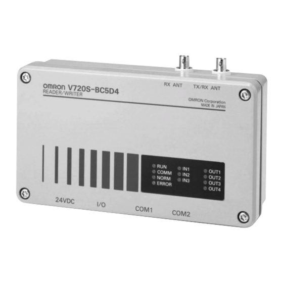
Page 18: Reader/Writer (V720S-Bc5D4)
Reader/Writer (V720S-BC5D4) Section 2-1 Reader/Writer (V720S-BC5D4) 2-1-1 Nomenclature 5. Receiving 4. Transmitting/receiving antenna connector antenna connector RX ANT TX/RX ANT V720S-BC5D4 OMRON Corporation RE A DER / WRITER MADE IN JAPAN 6. Indicators OUT1 COMM OUT2 NORM OUT3 ERROR OUT4... -
Page 19: Names Of Connector Terminals
Reader/Writer (V720S-BC5D4) Section 2-1 2-1-2 Names of Connector Terminals Each connector shows pin numbers ,which are viewed from the outside of the Reader/Writer. 1. Power connector Shape of Name Description connector number + 24 VDC Connects the + side of 24 VDC. Connecting to a ground of 100 Ω... -
Page 20: Specifications
Specifications Section 2-2 Specifications 2-2-1 General Specifications Item Specifications Supply voltage 24VDC ±10% Power consumption V720S-BC5D4: 25W or less Ambient operating -10℃ to 50℃ (with no icing) temperature Ambient operating humidity 35% to 85% RH (with no condensation) Ambient storage -25℃... -
Page 21: Reader/Writer Communications Specifications
Specifications Section 2-2 2-2-3 Reader/Writer Communications Specifications 1. Transmission specifications Item Specifications Central carrier frequency 13.56 MHz ± 7 kHz V720S-BC5D4: 4.0 W or less Antenna output Output impedance: 50 Ω Modulation method Degree of modulation 10 % to 20 % Standard mode: 1 out of 256 Coding method Fast mode: RZ... -
Page 22: I/O Specifications
Specifications Section 2-2 2-2-4 I/O Specifications Input specifications (RST, IN1, IN2, and IN3) Output specifications (OUT1, OUT2, OUT3, and OUT4) Item Specifications Item Specifications 24VDC ± 10% 24VDC ± 10%, 50mA Max. opening and Input voltage (including ripples) closing capacity (including ripples) Input impedance 2.2 k Ω... -
Page 23: Host Communications Specifications
Specifications Section 2-2 2-2-5 Host Communications Specifications COM1 connector Item Description Conforming standard RS-232C or RS-485 Communications EIA/TIA-232-E half duplex or method EIA/TIA-485 half duplex Baud rate 9600 bps, 19200 bps, 38400 bps, 115200 bps Sync Start-stop synchronization (stop bit: 1 or 2) Transmission code ASCII7 or JIS8 unit symbols Max. -
Page 24: Dimensions
Specifications Section 2-2 2-2-6 Dimensions 147.5 35.0 43.0 247.0 V 720 ‑B C 5D 4 235.0 50.5 35.0 40.0 35.0 65.0... -
Page 25: Cable (Sold Separately)
Cable (sold separately) Section 2-3 Cable (sold separately) 2-3-1 General Specifications Model V720-A 40 V720-A 50 V720-A 60 Item Antenna cable Power cable RS-232C cable Cable type Coaxial cable Number of conductors 2 (shield) Insulation resistance 10 M Ω min. (at 250 5 MΩ... - Page 26 Cable (sold separately) Section 2-3 - Power cable: V720-A50 Item Model V720-A50 Length (L1) 3000+10-20(mm) Connection label Red(+24VDC) Black(0V) White(GR) Connector (Reader/Writer side) - Cable for RS-232C: V720-A60 Item Model V720-A60 3M V720-A60 15M Length (L1) 3000+50-0(mm) 3000+50-0(mm) Connection label Connector (Host side) Connector (Reader/Writer side) Note The D-sub connector is an inch screw thread(M2.54) type.
-
Page 27: Memory Map Of Tag
This chip consists of a 64-byte memory. The upper five blocks (Blocks 0 to 4) of the memory are used as a system area having functions that do not relate to user memory. OMRON offers special commands for accessing this area in order to ensure the great ease of these functions by the user. - Page 28 Memory Map of Tag Section 2-4 2-4-1 I.CODE1 Chip (Philips Semiconductor IC;SL1 ICS30 01,SL ICS31 01) 1) SNR (pages FB and FC) SNR is a Tag-specific code and has been written into the memory during the chip production process. The IC is shipped with this page write-access inhibited (refer to page FD); there is no way of making this page rewritable by the user.
-
Page 29: I.code2 Chip (Philips Semiconductor Ic; Sl2 Ics20)
ISO/IEC15693, however, the operating verification is performed for the Tag incorporating Philips Semiconductor IC; SL21CS20 (commonly called as I-CODE2). For other manufacturers’ tags and/or Omron’s tags incorporating other chips with accordance with ISO/IEC15693, you are recommended to verify the test of those products thoroughly. - Page 30 Memory Map of Tag Section 2-4 2. System area of I.CODE2 chip This section describes a system area of I.CODE2 chip. The system area of I-CODE2 is allocated in the other area rather than user memory area. Execute a specific command to access to the system area. Byte0 Byte1 Byte2...
- Page 31 Memory Map of Tag Section 2-4 (4) DSFID DSFID indicates how data are organized in a memory. Byte3 DSFID (5) Write-access conditions The pages are write-inhibited permanently if they are so indicated in the memory map. The factory settings are as follow. If the bit of a particular page is 1, that page is write-protected.
-
Page 32: Functions
SECTION 3 Functions Single, FIFO, Multiple, and Selective Access Functions.......... 3-2 3-1-1 Single Access Mode....................3-2 3-1-2 FIFO Access Mode ....................3-2 3-1-3 Multiple Access Mode .................... 3-3 3-1-4 Selective Access Mode ..................3-3 Memory Check Function ..................3-4 3-2-1 Usage ........................ -
Page 33: Single, Fifo, Multiple, And Selective Access Functions
Single, FIFO, Multiple, and Selective Access Functions Section 3-1 Single, FIFO, Multiple, and Selective Access Functions This Reader/Writer has four communication modes to be selected by each command corresponding to the number and/or state of Tags in the communication area. In addition, two operating modes (ISO and I.CODE1 modes) are provided, each of which can be selected according to the readout chip to be used. -
Page 34: Multiple Access Mode
Single, FIFO, Multiple, and Selective Access Functions Section 3-1 3-1-3 Multiple Access Mode This function is also called 1:N access or multiple Tag simultaneous access. In this mode, communications with multiple Tags in the communications area will be possible. Set the maximum number of Tags (number of timeslots) within the communications area (hereafter called the Tag number setting) using a command. -
Page 35: Memory Check Function
Memory Check Function I.CODE1 Mode Only Section 3-2 Memory Check Function I.CODE1 Mode Only By adding a check code to the data in the Tag, you can detect data errors due to the Tag memory (EEPROM) being overwritten, service life, and unforeseen factors. -
Page 36: Lock Function
Lock Function Section 3-3 Lock Function The Lock function protects data from being erased due to unintentional overwriting on the fixed data in the Tags. ■ Lock setting in ISO mode For the lock setting in ISO mode, you can write-protect any given areas by the page of Tag memory. -
Page 37: Distinguished Tag Read/Write Function
Distinguished Tag Read/Write Function Section 3-4 Distinguished Tag Read/Write Function Each of I.CODE2 and ISO/IEC chips has a one-byte identification code called AFI (Address Family Identifier) to find out the chip that is suitable for the application area of an antenna. I.CODE1 chip has two one-byte identification codes called the family code and Application ID, respectively. -
Page 38: External I/O Function
External I/O Function Section 3-5 External I/O Function 3-5-1 Eternal Input There are three external user inputs that can be controlled by commands. These can be used to design sequence operations, such as starting or stopping communications with Tags using external triggers. 3-5-2 External Input (1) There are four external user outputs that can be controlled by commands. -
Page 39: Eas Function
EAS Function Section 3-7 EAS Function This Reader/Writer supports EAS function of applications such as theft-prevention devices. This function supports the online mode to be executed by the commands from the host, and the offline mode to be executed only by Reader/Writer (See 3-6 “Offline Test Function”). -
Page 40: Setting, Mounting, And Connection Methods
SECTION 4 Setting, Mounting, and Connection Methods Reader/Writer Setting ..................4-2 4-1-1 Host Communications Setting (COM Port Setting)......... 4-2 4-1-2 Chip Operating Mode Setting ................. 4-3 4-1-3 Read Response Method Setting..............4-4 4-1-4 Antenna and Tag Communications Setting............. 4-4 4-1-5 Offline Mode Setting ..................4-5 4-1-6 Fixing of Settings.................... -
Page 41: Reader/Writer Setting
Reader/Writer Setting Section 4-1 Reader/Writer Setting The Reader/Writer has been designed for the user to make all the settings by issuing commands from the host. The user can use either the COM1 or COM2 port to make settings. However, we recommend use of the COM2 port because its communications settings have been fixed at factory to survive a power reset. -
Page 42: Chip Operating Mode Setting
Reader/Writer Setting Section 4-1 1) Communications type setting for COM1 port Set whether COM1 will be used as RS-232C or RS-485 by using the communications type setting command (CT) (refer to No. 4 in 5-6-8 of Section 5). Setting name Default set value Setting range (command name) -
Page 43: Read Response Method Setting
Reader/Writer Setting Section 4-1 4-1-3 Read Response Method Setting • SNR addition setting Select whether or not SNR (a serial number representing an ID unique to a Tag) will be added to the response when a read-related command is exe- cuted. -
Page 44: Offline Mode Setting
Reader/Writer Setting Section 4-1 4-1-5 Offline Mode Setting Set whether the Reader/Writer will start in offline mode or online mode. If you choose offline mode, the Reader/Writer will perform EAS check inde- pendent of the host. This setting can be made by using the offline mode setting command (FL) (refer to No. -
Page 45: Installation Environment
Installation Environment Section 4-2 Installation Environment The V720S-BC5D4 Reader/Writer is a highly reliable control device with- standing tough environments. In order to ensure the full, reliable performance of the RFID system, however, observe the following. 4-2-1 Installation • Do not install the Controller under the following conditions. •... -
Page 46: Mounting Method
Mounting Method Section 4-3 Mounting Method The Reader/Writer must be mounted using a mounting plate. When mounting, be sure to secure it onto the mounting plate with M6 screws, spring washers and flat washers. Do not apply organic solvent, e.g., screw lock solvent, to the screws to secure the Reader/Writer. -
Page 47: Wiring Method
Reader/Writer side Connector plug (accessory) Connected to Pin num- Name 24 VDC + 24 VDC • Recommended Compact DC Power Supply (OMRON) Model Output capacitance Input voltage S82K-03024 24VDC at 1.3A 100/200V Note • Use 24 VDC to supply power to the Reader/Writer. When you use the recommended power supply, S82K-03024, and a cable with a thickness of AWG16, the cable can be extended to 7 meters at maximum.If a longer... -
Page 48: Host Communications Cabling
Wiring Method Section 4-4 4-4-2 Host Communications Cabling 4-4-2-1 RS-232C Interface Cabling Antenna cable V720-A40 Host communications Power cable cable Host computer Reder/Writer Pin layout when cable connector on (COM1, COM2) Reader/Writer is viewed from engaging face + - Shield wire •... - Page 49 Connector of cable 25ピン、オス 25-pin, male COM1, COM2 + - Shield wire (シールド線) 3) Connection to OMRON C200H PLC (Pin layout when cable connector is viewed from engaging face) Reader/Writer Connecting Devive C200H ASC02 リーダライタ 接続機器 形 C200H-ASC02 Connector of cable C O M 1 、...
-
Page 50: Interface Cabling
RX ANT TX/RX ANT RX ANT TX/RX ANT RX ANT TX/RX ANT V720-BC5D1 V720-BC5D1 V720-BC5D1 OMRON Corporation OMRON Corporation OMRON Corporation RE A DER / WRITER RE A DER / WRITER RE A DER / WRITER MADE IN JAPAN MADE... - Page 51 Wiring Method Section 4-4 1) Example of wiring for 1-to-1 connection V720S-BC5D4 V720-BC5D1 上位機器 Host + COM1 COM2 - Terminal resistance Terminal resistance 終端抵抗220Ω 終端抵抗220Ω 220Ω is on 220Ω is on あり あり Note Be sure to turn on the terminal resistance on both the host and Reader/Writer sides.
- Page 52 Wiring Method Section 4-4 ■ Example of wiring between host and Reader/Writer Host side Reader/Writer side Pin layout when cable connector on Connector plug Reader/Writer is viewed from engagingface Con- (accessory) nected Pin num- Name 1 2 3 Port COM1 COM2 Terminal No.
-
Page 53: Assembly Of Connector
Wiring Method Section 4-4 4-4-3 Assembly of Connector 4-4-3-1 Assembly of Host Communications Connector and I/O Connector 1) Disassemble the connector as follows: a) Loosen the set screws and remove the barrel from the end bell (by turning it counterclockwise). b) Loosen Set Screw B, remove the clamp nut from the end bell, and pull out the washer and the cable packing. - Page 54 Before use, be sure to check for the proper torques and the waterproof effects of the cable of your choice. OMRON does not offer any guarantee for customer-made cables. Please inquire to the manufacturer for details of these connectors.
-
Page 55: Assembly Of Connector
Wiring Method Section 4-4 4-4-3-2 Assembly of Connector 1) Strip a part of the envelopes of the cable terminal and the conductors according to the measurements specified in Tables A and B. Conductor envelope Envelope 2) Insert the fastening nut, washer, gasket, washer, rear shell, and con- necting ring (this is not necessary if a jack is used) in this order at any desired part of the cable. - Page 56 Model name of power connector: 1108-12A10-3AF (8.6) from Tajimi Musen Electronics Co., Ltd. OMRON has established a range of cables suitable for the 1108 series products of 0.3 mm to 0.8 mm in diameter of their cord feed ports. Please...
- Page 57 Wiring Method Section 4-4 4-18...
-
Page 58: Control From Host
SECTION 5 Control from Host Reader/Writer under Operating Conditions ............3 5-1-1 Reader/Writer under Operating Conditions ............3 5-1-2 Communications Phase ..................3 (1) No Response ....................3 (2) 1-to-1......................3 (3) Multiple Response ..................4 5-1-3 ACK/NACK Control....................4 (1) Host Receives a Normal Response and Sends ACK Command .... - Page 59 5-6-2 Reader/Writer AFI Read (AF): ISO Mode Only..........37 5-6-3 Read and Write of Family Code (for Reader/Writer) (FC): I.CODE1 Mode Only ..................38 5-6-4 Read and Write of Application (AI): I.CODE1 Mode Only........39 5-6-5 SNR Addition Setting (SN)................. 40 5-6-6 Node Number Setting Command (NN) ..............
-
Page 60: Reader/Writer Under Operating Conditions
Section 5-1 Reader/Writer under Operating Conditions 5-1-1 Reader/Writer under Operating Conditions The V720S series of RFID system receives a command (1) from the host, communicates with the Tag (2), and returns its result to the host as a response (3). Antenna... -
Page 61: Multiple Response
Reader/Writer under Operating Conditions Section 5-1 (3) Multiple Response Multiple responses are sent per command when the following commands have been specified: Sin- gle Repeat, FIFO Repeat, Multi-trigger, Multi-repeat, or Selective Access (for commands that com- municate with Tags). Host Command Controller Response... -
Page 62: Command And Response Frame Structures
Command and Response Frame Structures Section 5-2 Command and Response Frame Structures 5-2-1 Command Frame Structure The Reader/Writer continuously receives signals from STX through ETX, and executes the com- mand when the correct node number is received (*1). If, after receiving an STX signal, another STX signal is received before an ETX signal is received, the second STX signal is given command prior- ity. -
Page 63: Command Code List
Command and Response Frame Structures Section 5-2 5-2-3 Command Code List There are four major types of commands. (1) Communications command This command communicates with a Tag. (2) System command This command accesses to the system area of a Tag. (3) Reader/Writer control command This command controls the Reader/Writer, e.g. -
Page 64: Response Command List
Command and Response Frame Structures Section 5-2 5-2-4 Response Command List Response codes in response frames are shown below. Response Type Name Description Code Normal “00” Normal completion The received command ends normally with no error. completion “72” Multi-processing end Communications end response when a multi-trigger function is used. -
Page 65: Example Bcc Calculation
Command and Response Frame Structures Section 5-2 1) Correlation table of ISO/IEC Error Codes When a Tag incorporating ISO/IEC chip (including I.CODE2 chip) returns an error response, the Reader/Writer responses a Response Code shown in the table below. ISO code Description Response code of module An unadopted command. -
Page 66: Communications Commands And Responses
Communications Command Section 5-3 Communications Commands and Responses This section describes commands and responses when BCC has been enabled. When BCC has been disabled, BCC is not attached to either the command or response frames. 5-3-1 Read (RD) This command reads data from a Tag in the communications area. <Command Format>... -
Page 67: Write (Wt)
Communications Command Section 5-3 (2) Completion of communications (Multi/Trigger only): When the communications with all tags in communications area is completed. Node No. Response ETX BCC Retry Command Flag Code Code “RD” “72” Response code 00: Normal completion For other response codes, refer to 5-2-4 Response Code List. UID (SNR) Indicates UID (SNR) having been read from a Tag. - Page 68 Communications Command Section 5-3 Caution From Page FD to Page FE is a system area for write-protect and QUIET/EAS settings. Depending on the content of write data, a Tag may become write-protected or inaccessible, so be sure to understand these pages fully before use.
-
Page 69: Tag Detection (Rd): I.code1 Mode Only
Communications Command Section 5-3 5-3-3 Selective Access Read/Write 5-3-3-1 Tag Detection (RD): I.CODE1 Mode Only This command assigns temporary Tag numbers to each of multiple Tags that are present in the communications area. This command is available only when the system is in I.CODE1 mode. In ISO mode, you must enable UID (SNR) additional setting, execute 5-3-1 Read Command (RD), and get UID since the system uses UID (SNR) data as a temporary number. -
Page 70: Selective Access Read (Rd)
Communications Command Section 5-3 5-3-3-2 Selective Access Read (RD) In ISO mode, this command reads data from the Tag in communications area by specifying UID (SNR). In I.CODE1 mode, this command reads data from the Tag which is specified by the Temporary Number. -
Page 71: Selective Access Write (Wt)
Communications Command Section 5-3 5-3-3-3 Selective Access Write (WT) This command writes data to the Tag of either UID (SNR) (in ISO mode) or Temporary Number (in I.CODE1 mode). <Command Format> Communi- Data First write First write UID(SNR) Write ETX BCC Node Command code cations... -
Page 72: Special Read (Rd): For I.code1 Mode Only
Communications Command Section 5-3 Caution From Page FD to Page FE is a system area for write-protect and QUIET/EAS settings. Depending on the content of write data, a Tag may become write-protected or inaccessible, so be sure to understand these pages fully before use. -
Page 73: Polling Single Auto Read (Pr)
Communications Command Section 5-3 5-3-5 Polling Single Auto Read (PR) Immediately after receiving the Polling Single Auto Read Command, the Reader/Writer returns a re- sponse indicating the acceptance of the command, and waits for a Tag to enter the communications area of the Antenna. -
Page 74: Polling Single Auto Write (Pw)
Communications Command Section 5-3 5-3-6 Polling Single Auto Write (PW) Immediately after receiving the Polling Single Auto Write Command, the Reader/Writer returns a re- sponse indicating the acceptance of the command and waits for a Tag to enter the communications area of the Antenna. -
Page 75: Polling Check (Pc)
Communications Command Section 5-3 5-3-7 Polling Check (PC) You can check the results while the Polling Single Auto Read Command and Polling Single Auto Write Command are being executed. You can use Polling Check after the Polling Single Auto Read Command and Polling Single Auto Write Command have been sent. -
Page 76: Polling End (Pe)
Communications Command Section 5-3 5-3-8 Polling End (PE) This command aborts the execution of Polling commands. It is used after a Polling command is sent. <Command Format> Node No.. Command code ETX BCC “PE” <Response Format> (1) Before the completion of communications with a Tag Command code Retry Response... -
Page 77: Memory Calculation (Mk): I.code1 Mode Only
Communications Command Section 5-3 5-3-10 Memory Calculation (MK): I.CODE1 Mode Only This command uses the generating polynomial, X16 + X12 + X5 + 1 to calculate the range of the check block designated by a user and writes the check code to the last page of the check block. <Command Format>... -
Page 78: System Command
System Command Section 5-4 System Command 5-4-1 System Read (SR): ISO Mode Only This command read system information in the system area of the Tag. <Command Format> ETX BCC Node No.. Command code System “SR” type method“00” Tag type Specified a Tag type A: I.CODE2 chip System method Specified the kind of system information. -
Page 79: System Write (Sw): Iso Mode Only
System Command Section 5-4 5-4-2 System Write (SW): ISO Mode Only This command writes the settings of AFI, DSFID, and EAS to a Tag. <Command Format> (1) For normal write data ETX BCC Node No.. Command code System “SW” type method (2) When UID of a Tag is specified ETX BCC... -
Page 80: System Lock (Sl): Iso Mode Only
System Command Section 5-4 5-4-3 System Lock (SL): ISO Mode Only This command locks (write-inhibit) to write to system area information of a Tag. <Command Format> (1) Normal lock ETX BCC Node No.. Command code System “SL” type method (2) In a case where UID of a Tag is specified ETX BCC Node No.. -
Page 81: Snr (Tag-Specified Code) Read (Rd): I.code1 Mode Only
System Command Section 5-4 5-4-4 SNR (Tag-specified Code) Read (RD): I.CODE1 Mode Only This command read SNR (Tag-specified code) which incorporates I.CODE1 chip. Refer to 2-4 of Section 2 Memory Map of Tag. <Command Format> Communica- Data Fixed value Fixed value ETX BCC Node No.. -
Page 82: Read (Rd) Of Family Code And Application Id (For Tag): I.code1 Mode Only
System Command Section 5-4 5-4-5 Read (RD) of Family Code and Application ID (for Tag): I.CODE1 Mode Only This command is used to read the Family Codes and Application IDs from Tags incorporated I.CODE1 chip.. <Command Format> Node No.. Command code Communi- Data Fixed... -
Page 83: Write (Wt) Of Family Code And Application Id (For Tag) Tag: I.code1 Mode Only
System Command Section 5-4 5-4-6 Write (WT) of Family Code and Application ID (for Tag) Tag: I.CODE1 Mode Only This command is used to write Family Codes and application IDs to Tags incorporating I.CODE1 chip. There is no need to perform the verify read process, since this command performs it as part of its execution. -
Page 84: Eas Setting (Es): I.code1 Mode Only
System Command Section 5-4 5-4-7 EAS Setting (ES): I.CODE1 Mode Only This command sets the EASBit of a Tag incorporating I.CODE1 chip. When the EASBit is disabled, the Reader/Writer will not return a response to the EAS Check Command (EA). <Command Format>... -
Page 85: Lock Setting (Lk): Iso Mode Only
System Command Section 5-4 5-4-9 Lock Setting (LK): ISO Mode Only This command is used to set and check the write-protection of Tags incorporating I.CODE1 chip. A Tag can be locked (or write-protected) by memory page. <Command Format> First lock page lock ETX BCC Node No.. -
Page 86: Lock Setting Read (Lr): Iso Mode Only
System Command Section 5-4 5-4-10 Lock Setting Read (LR): ISO Mode Only This command reads lock setting information of a Tag incorporating I.CODE2 chip. <Command Format> First lock page No. of lock ETX BCC Node No.. Command code type pages “LR”... -
Page 87: Lock Setting (Lk): I.code1 Mode Only
System Command Section 5-4 5-4-11 Lock Setting (LK): I.CODE1 Mode Only This command is used to set and check the lock (write-protection) of Tags incorporating I.CODE1 chip. A Tag can be locked (or write-protected) by memory page. To read lock information set in a Tag, set all lock information in the commands to 0. -
Page 88: Eas Check (Ea)
System Command Section 5-4 5-4-12 EAS Check (EA) This command transmits the EAS command continuously and returns the percentage of data that matches the EAS response code. <Command Format> ●In ISO mode ETX BCC Node No.. Command code type “EA” ●In I.CODE1 mode ETX BCC Node No.. -
Page 89: Stop (St)
Reader/Writer Control Command Section 5-5 Reader/Writer Control Command These are commands for reading and writing Tags from and to the user memory. 5-5-1 Stop (ST) This command causes the Reader/Writer to abort the execution of Auto Mode, Repeat Mode, FIFO Access, Selective Access, EAS Check and other commands and return to wait mode for a com- mand. -
Page 90: Nack (Nk)
Reader/Writer Control Command Section 5-5 5-5-4 NACK (NK) This command is used during ACK/NACK control to inform the Reader/Writer that the host device did not normally receive a response from the Reader/Writer. When the Reader/Writer receives a NACK command, the previous response is retried provided that the maximum number of retries (9) has not been exceeded. -
Page 91: Test (Ts)
Reader/Writer Control Command Section 5-5 5-5-6 Test (TS) This command returns test messages sent from the host with no change made. The test command is used for testing communications between the host and the Reader/Writer and other purposes. <Command Format> Node No. -
Page 92: Version (Vs)
Reader/Writer Control Command Section 5-5 5-5-7 Version (VS) This command reads the software version for the Reader/Writer. <Command Format> Node No. Command ETX BCC code "VS" <Response Format> Node No. Retry Command Response Software version ETX BCC flag code code "VS"... -
Page 93: Setting Command
Setting Command Section 5-6 Setting Command 5-6-1 Reader/Writer AFI Enable/Disable Changeover (AE): ISO Mode Only In ISO mode, you must set AFI of the Reader/Writer either enable or disable when communicating with a Tag. If you set AFI enable, only Tags, which has the same AFI, can be communicated. When you set AFI disable, the communications are enabled no matter AFI in Reader/Writer is set or not. -
Page 94: Reader/Writer Afi Read (Af): Iso Mode Only
Setting Command Section 5-6 5-6-2 Reader/Writer AFI Read (AF): ISO Mode Only In ISO mode, you must set and read AFI of the Reader/Writer. When you set AFI enable, only Tags, which has the same AFI, can be communicated. When the setting is “00”, the communications are enabled. -
Page 95: Read And Write Of Family Code (For Reader/Writer) (Fc): I.code1 Mode Only
Setting Command Section 5-6 5-6-3 Read and Write of Family Code (for Reader/Writer) (FC): I.CODE1 Mode Only The FC Command is used to set or read the Family Code in the Reader/Writer. Only Tags that have the same Family Code as the one set by this command can perform communications. If this Family Code is set to 00, communications will be possible with all Tags. -
Page 96: Read And Write Of Application (Ai): I.code1 Mode Only
Setting Command Section 5-6 5-6-4 Read and Write of Application (AI): I.CODE1 Mode Only This Command is used to set or read and read the application ID in the Reader/Writer in 1.CODE1 Mode Only Tags that have the same application ID as the one set by this command can perform communications. -
Page 97: Snr Addition Setting (Sn)
Setting Command Section 5-6 5-6-5 SNR Addition Setting (SN) This command selects whether SNR will be added to a response to a Read Command (excluding Special Read). <Command Format> Node No. Command Addi- ETX BCC code tion "SN" mode Addition mode Specify whether SNR will be added to a response. -
Page 98: Node Number Setting Command (Nn)
Setting Command Section 5-6 5-6-6 Node Number Setting Command (NN) This command sets and reads the node number of the Amp-Reader/Writer. <Command Format> Node No. Command Node number ETX BCC code change speci- "NN" fication Node number Specifies the node number in decimal that you want to change. change specifica- Specification range: 00 to 31, * tion... -
Page 99: Communications Port Setting Command (Cp)
Setting Command Section 5-6 5-6-7 Communications Port Setting Command (CP) This command sets the baud rate for the communications port (COM Port), data length, parity bit, and stop bit for use in communications with the host. <Command Format> Node No. Command Port Baud... -
Page 100: Communications Type Setting (Ct)
Setting Command Section 5-6 <Response Format> Node No. Retry Command Response Port Baud Data Parity Stop Time- ETX BCC flag code code: rate length Enabled NACK "CP" "00" /Disabled Response code: 00: Normal completion For other response codes, refer to 5-10 Response Code List. Port No. -
Page 101: Tag Communications Mode (Cm)
Setting Command Section 5-6 5-6-9 Tag Communications Mode (CM) This command sets and reads the communications mode for use in communications with Tags. <Command Format> Node No. Command Commni- ETX BCC code cations "CM" mode Communica- Specify the number corresponding to the communications mode tions mode that you want to select for communications with Tags. -
Page 102: Antenna Changeover Command (Ac)
Setting Command Section 5-6 5-6-10 Antenna Changeover Command (AC) This command selects whether the receiving function of each antenna will be enabled or disabled. <Command Format> Node No. Command ETX BCC code tenna "AC" selec- tion Antenna selec- Specify the number corresponding to how TX/RX ANT and RX tion ANT will be used. -
Page 103: Terminal Resistance Setting Command (Tm)
Setting Command Section 5-6 5-6-11 Terminal Resistance Setting Command (TM) This command sets and reads the terminal resistance (for RS-485). <Command Format> Node No. Command Terminal ETX BCC code specifi- "TM" cation Terminal Specify the value, 0 or 1, that corresponds to the terminal resistance that specification you want to change. -
Page 104: Offline Mode Setting (Fl)
Setting Command Section 5-6 5-6-12 Offline Mode Setting (FL) This command selects whether the Reader/Writer will start in offline mode or offline mode. When offline mode is selected, the Reader/Writer will perform EAS check independent of the host, and output a signal from the output port (OUT1) if the result exceeds the specified criterion. <Command Format>... -
Page 105: Initialization Of Settings Command (Is)
Setting Command Section 5-6 5-6-13 Initialization of Settings Command (IS) If necessary, you can return all the settings to their factory settings. <Command Format> Node No. Command ETX BCC code "IS" <Response Format> Node No. Retry Command Response ETX BCC flag code code:... -
Page 106: Operating Mode Changeover (Ty)
Setting Command Section 5-6 5-6-15 Operating Mode Changeover (TY) This command changes the operating mode (ISO/I.CODE1) of the Reader/Writer. <Command Format> Node No.. Command code ETX BCC “TY” type Tag type Specifies the mode. 0: I.CODE1 mode 1: ISO mode When the Operating Mode is set to "**,"... -
Page 107: Other Commands
Other Commands Section 5-7 Other Commands 5-7-1 Command Undefined Response When the Reader/Writer receives a command code which is not on the command list, the Reader/Writer returns the Command Undefined Response. <Response Format> ETX BCC Node No.. Command code “IC” 5-50... -
Page 108: Communications Method
Communications Method Section 5-8 Communications Method The operation sequence, e.g., how communications with a Tag will take place and when a response will be returned, varies depending on the specification made for a command. For communications, settings for access and mode should be made according to the state of Tags n the communications area of the Antenna and their operation after the Tags receive commands. -
Page 109: Multiple Access
Other Commands Section 5-8 5-8-1-3 Multiple Access In multiple access, communications with all of Tags existing in the communications area can be car- ried out. In this case, the Tag No. setting commensurate with the number of Tags within the commu- nications range is set using the commands. -
Page 110: Selective Access
Communications Method Section 5-8 5-8-1-4 Selective Access A Selective Access has a function to communicate with the selected Tags among Tags in the com- munications area of antenna. This access has different processing according to the modes of the Reader/Writer. <ISO mode>... -
Page 111: Selective Access Operation: In Iso Mode
Other Commands Section 5-8 ■Selective Access Operation: In ISO Mode (Host) (Controller) (Tag) (1) Controller receives a command. Multi-Read Command (UID Additional Setting) (2) Controller communicates with the Tag. Waits for a Tag Tag (UID1) A response (UID1) (3) Controller returns a response with UID. Receives a response Tag (UID2) Tag detection... -
Page 112: Selective Access Operation: In I.code1 Mode
Communications Method Section 5-8 ■Selective Access Operation: In I.CODE1 Mode (Host) (Reader/Writer) (Tag) Tag Detection Command (RD) (1) Reader/Writer receives a command (2) The Reader/Writer communicates with the Communications process Tag (0) Tag; it Adds a temporary number to the re- sponse and stores it within the Controller. -
Page 113: Mode Settings
Other Commands Section 5-8 Exceptions When the Tags with the temporary numbers selected by the Tag Selection Command are not pre- sent, the Reader/Writer returns a communications error to the host. When the Tag Selection Command selects temporary numbers other than those stored by the Reader/Writer by the Tag Detection Command, the Reader/Writer returns a format error to the host. -
Page 114: Auto Mode
Communications Method Section 5-8 5-8-2-2 Auto Mode In auto mode, after receiving an Auto command from the host, the Reader/Writer waits for a Tag to enter the Antenna’s communications area. Since the Reader/Writer is in a busy state between Auto command reception and the completion of communications with the Tag, it does not accept any commands other than the Stop or Reset Command during the period. -
Page 115: Repeat Mode
Other Commands Section 5-8 5-8-2-3 Repeat Mode The Reader/Writer waits for a Tag to enter the R/W Antenna’s communications area. Every time an Tag enters the communications area, the Reader/Writer communicates with the Tag and returns a response. It is not until communications are stopped by the Stop or Reset command that the Reader/Writer accepts the next command. -
Page 116: Polling Auto Mode
Communications Method Section 5-8 5-8-2-4 Polling Auto Mode If an Auto command is used when a single host controls more than one Reader/Writer, the commu- nications path between the host and one of the Reader/Writers to which the command is sent be- comes busy, disabling the host to control other Reader/Writers. -
Page 117: Table Of Communications Methods
Other Commands Section 5-8 5-8-3 Table of Communications Methods Name Code Description Single Trigger Immediately after receiving a command, the Reader/Writer communicates with a Tag and returns a response. If the Tag is missing, an error is returned. During communications, only one Tag should exist in the communications area. Single Auto After receiving a command, the Reader/Writer waits for a Tag to enter the com- munications area. -
Page 118: Table Of Communications Methods For Commands
Communications Method Section 5-8 5-8-4 Table of Communications Methods for Commands Communica- Single FIFO Multiple Selective tions Special Method Read Tri- Tri- Tri- Auto Repeat Auto Repeat Repeat Detec- Selec- gger gger gger tion tion Command Read − − − Note −... -
Page 119: Data Type
Data Type Section 5-9 Data Type Specify using the commands whether read/write data is to be handled as ASCII (or JIS8 code) char- acter data, or as hexadecimal numerical data. Name Code Description ASCII Code A character of data occupies 1 byte (1 address) on a Tag as an ASCII code or a JIS 8 code. -
Page 120: Timeslot Setting
Timeslot Setting Section 5-10 5-10 Timeslot Setting The timeslot setting is the setting in the command frame when communicating with multiple Tags simultaneously using Multi-system commands. This setting must be set according to the number of Tags with which to communicate simultaneously. Refer to the table below for the relationship be- tween the number of Tags and this setting. -
Page 121: Command Connection: In I.code1 Mode
Command Connection: In I.CODE1 Mode Section 5-11 5-11 Command Connection: In I.CODE1 Mode This Command Connection works in I.CODE1 Mode Only, and does not support ISO Mode. A command connection function allows the Reader/Writer to perform a pair of read and write opera- tions at a time by sending a command only once. - Page 122 Command Connection: In I.CODE1 Mode Section 5-11 The Following Combinations of Command Connections Are Possible Command (1) Memory Memory Polling Read Write Polling read Calculation check write (RD) (WT) (PR) (MK) (MC) (PW) Read(RD) − − − − Write(WT) − −...
-
Page 123: Startup And Full Operation
SECTION 6 Startup and Full Operation Trial Operation ......................6-2 Self-diagnostics ......................6-3 Errors and Remedies....................6-4 Maintenance and Inspection..................6-5 Troubleshooting ......................6-6... -
Page 124: Trial Operation
Section 6-1 Trial Operation Items Check the following on the RFID System before the trial operation of the whole system. Items Detail Section-Item Power supply and I/O Are the power supply and I/O lines lines 1 properly wired? Are the terminal screws fastened tightly? Reader/Writer Setting Is the node number set correctly? 2... -
Page 125: Self-Diagnostics
Errors and Remedies Section 6-2 Self-diagnostics The Reader/Writer has a self-diagnostic function to check a variety of items in order to reduce the downtime of the system that may result due to operational failures. Details of Errors Errors detected by the Reader/Writer can be classified into “fatal errors” and “nonfatal errors.”... -
Page 126: Errors And Remedies
Errors and Remedies Section 6-3 Errors and Remedies The following are considered to be main causes of system breakdowns. • Noise Interference ........Take appropriate countermeasures against noise. • Failures in any of the external devices • Failures in the Reader/Writer •... -
Page 127: Maintenance And Inspection
Maintenance and Inspection Section 6-4 Maintenance and Inspection The V720 Series must be inspected on a daily or regular basis so that the functions of the V720 Series can be used in good condition. The V720 Series consists of semiconductors that last almost indefinitely. The following malfunctions may, however, result due to the operating environment and conditions. -
Page 128: Troubleshooting
Troubleshooting Section 6-5 Troubleshooting Use the following main check flowchart to determine the cause of the error. Main Check Flowchart Main Check Flow Is the system Go to System Connection Check connection normal? Flowchart (p.6 - 7) Abnormal Normal Is the host Go to Host Communications communicating Check Flowchart (p .6 - 8) - Page 129 Troubleshooting Section 6-5 System Connections Check Flowchart Start Are the connected connectors and cables OK? Connect normally. Turn power ON. Is the ERROR indicator flashing? Reset the Reader/Writer. Is the ERROR indicator Replace the Reader/Writer. ON or flashing? Is the RUN indicator ON? Is the rated voltage provided?
- Page 130 Troubleshooting Section 6-5 Host Communications Check Flowchart Start Start the TS command from the host. Is the response normal? Is the communications frame OK? Revise the communications frame correctly. Are the communications cable connectors wired OK? Wire the connectors correctly. Is the host working normally? Revise the host program...
- Page 131 Troubleshooting Section 6-5 Communications Check Flowchart Start Turn ON the Controller and connect the host. Send the WRITE command in single auto mode. Does the COMM indicator go from ON to OFF? Is the direction Is the moving Is the ambient Is the End code 70? between Antenna...
- Page 132 Troubleshooting Section 6-5 Operating Environment Check Flowchart Start Refer to 6-4 Maintenance Are the operating and Inspection. conditions OK? Refer to 6-3 Errors and Is the ambient noise OK? Remedies. 6-10...
-
Page 133: Reference Data
SECTION 7 Reference Data Communications Time ....................7-2 Calculation of Tag Traveling Speed................7-4... -
Page 134: Communications Time
Communications Time Section 7-1 Communications Time In the V720S-series Reader/Writer, actual communications with a Tag are performed by reading or writing four-byte data per page. • The following chart specifies the TAT (turn-around time) and actual communications time. The actual communications time in the following chart is the time required for communications •... - Page 135 Communications Time Section 7-1 2) Fast mode 1 8 0 1 8 0 T A T ( m s ) 1 6 0 Actual 1 6 0 communicat 1 4 0 1 4 0 Writing ions time (ms) Writing 1 2 0 1 2 0 1 0 0 1 0 0...
-
Page 136: Calculation Of Tag Traveling Speed
Calculation of Tag Traveling Speed Section 7-2 The total number of characters is 33, i.e., 15 characters in the command part and 18 characters in the response part. From this, the host communications time would be 33 * 11 bits /38400(bps) * 1000 = 9.5 (ms). -
Page 137: Appendix
SECTION 8 Appendix Appendix 1. Accessories....................8-2 Appendix 2. ASCII Code Table ..................8-3... - Page 138 Accessories Section Appendix 1 Appendix 1. Accessories Name Model Quantity Mounting plate (already attached to the Reader/Writer) Power connector plug 1108-12A10-3AF (8.6) from Tajimi Musen Electronics Co., Ltd. NJW-2010-PM10 from Nanaboshi Electric I/O connector plug Mfg. Co., Ltd. Host communication NJW-165-PM7 from Nanaboshi Electric Mfg.
- Page 139 ASCII Code Table Section Appendix 2 Appendix 2. ASCII Code Table High Order b8 - b5 0000 0001 0010 0011 0100 0101 0110 0111 Low Order b4 - b1 Colum 0000 (DLE) (SP) 0001 (SOH) 0010 (STX) " 0011 (ETX) 0100 (EOT) 0101...
- Page 140 ASCII Code Table Section Appendix 2...
- Page 141 Revision History A manual revision code appears as a suffix to the catalog number on the front cover of the manual. Cat. No. S919-E1-1 Revision code The following table outlines the changes made to the manual during each revision. Page numbers refer to the previous version.
- Page 142 Chao Yang District, Beijing 100022 China Tel: (86)10-6515-5778 to 5782 Fax: (86)10-6515-5801 to 5802 Up-to-date information on RFID Systems can be accessed at OMRON's web site at http://www.omron.com/card/rfid/ Authorized Distributor: Cat. No. S924-E1-1 Note: Specifications subject to change without notice.
Need help?
Do you have a question about the V720S Series and is the answer not in the manual?
Questions and answers