Table of Contents
Advertisement
Quick Links
UHF RFID System
V780-series
Reader/Writer
User's Manual
Standard Reader/Writer
V780-HMD68-ETN-JP
V780-HMD68-ETN-KR
V780-HMD68-ETN-CN
V780-HMD68-ETN-TW
V780-HMD68-ETN-IN
V780-HMD68-ETN-ID
V780-HMD68-ETN-MY
V780-HMD68-ETN-SG
V780-HMD68-ETN-EU
V780-HMD68-ETN-RU
V780-HMD68-ETN-US
V780-HMD68-ETN-MX
Slave Reader/Writer
V780-HMD68-ETN-JP-S
V780-HMD68-ETN-KR-S
V780-HMD68-ETN-CN-S
V780-HMD68-ETN-TW-S
V780-HMD68-ETN-IN-S
V780-HMD68-ETN-ID-S
V780-HMD68-ETN-MY-S
V780-HMD68-ETN-SG-S
V780-HMD68-ETN-EU-S
V780-HMD68-ETN-RU-S
V780-HMD68-ETN-US-S
V780-HMD68-ETN-MX-S
Z389-E1-08
Advertisement
Table of Contents

Related Manuals for Omron V780 Series


Summary of Contents for Omron V780 Series
- Page 1 UHF RFID System V780-series Reader/Writer User’s Manual Standard Reader/Writer Slave Reader/Writer V780-HMD68-ETN-JP V780-HMD68-ETN-JP-S V780-HMD68-ETN-KR V780-HMD68-ETN-KR-S V780-HMD68-ETN-CN V780-HMD68-ETN-CN-S V780-HMD68-ETN-TW V780-HMD68-ETN-TW-S V780-HMD68-ETN-IN V780-HMD68-ETN-IN-S V780-HMD68-ETN-ID V780-HMD68-ETN-ID-S V780-HMD68-ETN-MY V780-HMD68-ETN-MY-S V780-HMD68-ETN-SG V780-HMD68-ETN-SG-S V780-HMD68-ETN-EU V780-HMD68-ETN-EU-S V780-HMD68-ETN-RU V780-HMD68-ETN-RU-S V780-HMD68-ETN-US V780-HMD68-ETN-US-S V780-HMD68-ETN-MX V780-HMD68-ETN-MX-S Z389-E1-08...
- Page 2 No patent liability is assumed with respect to the use of the information contained herein. Moreover, because OMRON is constantly striving to improve its high-quality products, the information contained in this manual is subject to change without notice. Every precaution has been taken in the preparation of this manual. Neverthe- less, OMRON assumes no responsibility for errors or omissions.
-
Page 3: Introduction
Introduction Introduction Thank you for purchasing a V780-HMD68-ETN-/V780-HMD68-ETN--S RFID System. This manual contains information that is necessary to use the V780-HMD68-ETN-/V780-HMD68-ETN--S. Please read this manual and make sure you under- stand the functionality and performance of the Reader/Writer before you attempt to use it in an RFID system. -
Page 4: Terms And Conditions Agreement
Omron’s exclusive warranty is that the Products will be free from defects in materials and workman- ship for a period of twelve months from the date of sale by Omron (or such other period expressed in writing by Omron). Omron disclaims all other warranties, express or implied. - Page 5 Disclaimers Performance Data Data presented in Omron Company websites, catalogs and other materials is provided as a guide for the user in determining suitability and does not constitute a warranty. It may represent the result of Omron’s test conditions, and the user must correlate it to actual application requirements. Actual perfor- mance is subject to the Omron’s Warranty and Limitations of Liability.
-
Page 6: Safety Precautions
Safety Precautions Safety Precautions Definition of Precautionary Information The following notation and alert symbols are used in this User’s Manual to provide precautions required to ensure safe usage of the V780-HMD68-ETN-/V780-HMD68-ETN--S Reader/Writer. The safety precautions that are provided are extremely important to safety. Always read and heed the information provided in all safety precautions. - Page 7 Safety Precautions The V780-HMD68-ETN-ID/V780-HMD68-ETN-ID-S can be used only in Indonesia. The V780-HMD68-ETN-MY/V780-HMD68-ETN-MY-S can be used only in the Malaysia. The V780-HMD68-ETN-SG/V780-HMD68-ETN-SG-S can be used only in Singapore and Thailand. The V780-HMD68-ETN-EU/V780-HMD68-ETN-EU-S can be used in the European coun- tries under the RE Directive (2014/53/EU). The V780-HMD68-ETN-RU/V780-HMD68-ETN-RU-S can be used only in Russia.
-
Page 8: Precautions For Safe Use
Errors and Failures • If an error is detected in the Reader/Writer, immediately stop operation and turn OFF the power sup- ply. Consult with an OMRON representative. Maintenance • Using thinner, benzene, acetone, or kerosene may adversely affect the plastic parts and case coat- ing. -
Page 9: Precautions For Correct Use
Precautions for Correct Use Precautions for Correct Use Always observe the following precautions to prevent operation failures, malfunctions, and adverse effects on performance and equipment. Transportation • Always use the packing box that comes with the Reader/Writer when you transport it, and do not sub- ject it to excessive vibration or shock. - Page 10 Precautions for Correct Use Maintenance • Perform inspections both daily and periodically. • The Reader/Writer may fail if it or its wiring is replaced while the power supply is ON. Always turn OFF the power supply before you replace the Reader/Writer or its wiring. Compliance with Laws and Regulations •...
-
Page 11: Standards And Regulations
Standards and Regulations Standards and Regulations V780-HMD68-ETN-JP/V780-HMD68-ETN-JP-S is a wireless facility conforming to the construction type certification of premises radio station (920-MHz-band Moving Object Differentiation Wireless Facil- ities) based on the Japanese Radio Act. It cannot be used outside of Japan. Standards in Japan Premises Radio Station (920-MHz-band Moving Object Differentiation Wireless Facilities) (ARIB STD-T106 Standard) -
Page 12: Licensing Procedures Of Premises Radio Station
Licensing Procedures of Premises Radio Station Licensing Procedures of Premises Radio Station V780-HMD68-ETN-JP/V780-HMD68-ETN-JP-S is a wireless facility to differentiate moving object using the 920-MHz band. The licensing procedures of the premises radio station must be performed before use. Be sure to perform the licensing procedures before use. The licensing procedures are described in the Appendix. -
Page 13: Manual Structure
Manual Structure Manual Structure Page Structure The following page structure is used in this manual. Level 1 heading 7 Modbus/TCP Communications Level 2 heading Communications Procedure Level 3 heading Level 2 heading Give the current headings. In the computer, PLC, or other host devices, write the program to communicate with the Reader/Writer using TCP sockets. - Page 14 Manual Structure Special Information Special information in this manual is classified as follows: Precautions for Safe Use Precautions on what to do and what not to do to ensure safe usage of the product. Precautions for Correct Use Precautions on what to do and what not to do to prevent malfunction of the product or adverse affects on performances and functions.
-
Page 15: Sections In This Manual
Sections in this Manual Sections in this Manual Maintenance and Product Overview Inspection System Configuration Appendix Part Names and Index Functions Installation and Connections Preparations for Communications Functions Modbus/TCP Communications Browser Interface Troubleshooting UHF RFID System V780-series Reader/Writer User’s Manual (Z389) -
Page 16: Table Of Contents
CONTENTS CONTENTS Introduction ......................1 Terms and Conditions Agreement ................2 Safety Precautions ....................4 Precautions for Safe Use ..................6 Precautions for Correct Use..................7 Standards and Regulations ..................9 Licensing Procedures of Premises Radio Station ..........10 Manual Structure ....................11 Sections in this Manual .................. - Page 17 CONTENTS Section 4 Installation and Connections Installation..........................4-2 4-1-1 Reader/Writer ..........................4-2 4-1-2 RF Tags ............................4-4 Connections and Wiring ....................... 4-6 4-2-1 Connecting and Removing the Reader/Writer Power Cable and Ethernet Cable ...... 4-6 Section 5 Preparations for Communications Starting the Reader/Writer ....................
- Page 18 CONTENTS 6-9-3 Reception Level Monitor ......................6-47 6-9-4 Channel Monitor........................6-53 6-9-5 Focus Monitor ........................... 6-54 6-10 Multi-Reader/Writer Function ..................... 6-57 6-10-1 Outline............................6-57 6-10-2 Multi-Reader/Writer Modes ....................... 6-58 6-10-3 Application..........................6-63 6-10-4 Communications conditions during Multi-Reader/Writer use ............ 6-70 6-10-5 Maintenance functions during Multi-Reader/Writer use ............
- Page 19 CONTENTS Section 9 Troubleshooting Types of Errors ........................9-2 9-1-1 Errors Indicated on Operation Indicators ..................9-2 9-1-2 Errors Indicated with Error Codes....................9-3 Error Tables..........................9-4 9-2-1 Command Errors ........................9-4 9-2-2 System Errors ..........................9-6 9-2-3 WDT Errors..........................9-7 Errors and Countermeasures....................
-
Page 20: Revision History
Revision History Revision History A manual revision code appears as a suffix to the catalog number on the front and back covers of the manual. Z389-E1-08 Cat. No. Revision code Revision code Date Revised contents March 2017 Original production Multi-Reader/Writer function added October 2017 Content regarding models for various countries added (V780-HMD68-ETN-KR/-IN/-SG/-EU/-US/-MX) -
Page 21: Version Upgrade Information
Version Upgrade Information Version Upgrade Information This section describes the version upgrade details of firmware. Ver 1.00 → Ver 2.00 Change content Page Added “Auto” and “Focus” for the RF communications mode. P. 6-6 Expanded the access range of the user area in the RF tag with the communications command. P. - Page 22 Version Upgrade Information UHF RFID System V780-series Reader/Writer User’s Manual (Z389)
-
Page 23: Product Overview
Product Overview This section describes the features, overall operation flow, and product specifications of the V780 Reader/Writer. 1-1 Features ........... . . 1-2 1-2 Application Flowchart . -
Page 24: Features
Tags according to commands from a host device. V780 Reader/Writer RF Tag Integrated Structure The controller, amplifier, and antenna are integrated into the Reader/Writer for a simple structure. Previous OMRON models V780 Integrated Reader/Writer Reader/Writer Antenna Ethernet AC Adaptor (enclosed) - Page 25 1 Product Overview Simple Connection with Ethernet The highly generic Ethernet is used to connect to the host device to enable easy connection with Ether- net cable without any restrictions from the host PLC manufacturer. You can also use a switching hub to easily expand a system for connection of many Reader/Writers.
- Page 26 1 Product Overview Easy Operation with a Browser Interface A Web browser interface is built in, so you do not need special software. Just connect the computer to the Reader/Writer from your browser to easily communicate with RF Tags, make Reader/Writer settings, and monitor status. Computer Reader/Writer Switching Hub...
-
Page 27: Application Flowchart
1 Product Overview Application Flowchart A simple application flowchart is provided below. For correct application methods and details, refer to the reference page or section given for each step. Also, use the Startup Guide provided with the Reader/Writer to help you start operation. Installing the System 4-1 Installation on page 4-2 Connections and Wiring... -
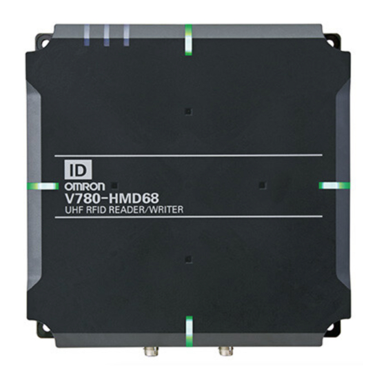
Page 28: Reader/Writer Specifications
1 Product Overview Reader/Writer Specifications 1-3-1 Appearance 1-3-2 General Specifications Item V780-HMD68-ETN- V780-HMD68-ETN--S Dimensions 250 × 250 × 70 mm (W × H × D, excluding protruding parts and cables) Supply voltage 24 VDC (−15% to +10%) Power consumption 10 W max. −10 to 55°C (with no icing) Ambient operating temperature Ambient operating humidity... - Page 29 1 Product Overview Regulations Model Regulations V780-HMD68-ETN-JP Premises Radio Station (920-MHz-band Moving Object Differentiation Wireless Facilities), ARIB STD-T106 V780-HMD68-ETN-JP-S V780-HMD68-ETN-KR V780-HMD68-ETN-KR-S V780-HMD68-ETN-CN Ministry of Information Industry No. 205 (2007) V780-HMD68-ETN-CN-S V780-HMD68-ETN-TW NCC LP0002 4.8 RFID V780-HMD68-ETN-TW-S V780-HMD68-ETN-IN the G.S.R.36 (E) V780-HMD68-ETN-IN-S V780-HMD68-ETN-ID PERDIRJEN POSTEL Nomor: 221/DIRJEN/2007...
-
Page 30: Tag Communications Specifications
1 Product Overview 1-3-3 Tag Communications Specifications V780-HMD68-ETN-JP/V780-HMD68-ETN-JP-S Item V780-HMD68-ETN-JP/V780-HMD68-ETN-JP-S Tag Communica- Applicable countries Japan tions Specifica- Maximum Radiated power 4 W e.i.r.p tions Output power 15 to 27 dBm (Switchable in 1-dB increments.) RSSI detection range Signal level: -35 to -61 dBm Noise level: -35 to -70 dBm (at end of antenna cable) Transmission speed from 40 kbps (fixed) - Page 31 1 Product Overview V780-HMD68-ETN-CN/V780-HMD68-ETN-CN-S Item V780-HMD68-ETN-CN/V780-HMD68-ETN-CN-S Tag Communica- Applicable countries China tions Specifica- Maximum Radiated power 2 W e.r.p tions Output power 15 to 27 dBm (Switchable in 1-dB increments.) RSSI detection range Signal level: -35 to -61 dBm Noise level: -35 to -70 dBm (at end of antenna cable) Transmission speed from 40 kbps (fixed) Reader/Writer to RF Tag...
- Page 32 1 Product Overview V780-HMD68-ETN-IN/V780-HMD68-ETN-IN-S Item V780-HMD68-ETN-IN/V780-HMD68-ETN-IN-S Tag Communica- Applicable countries India tions Specifica- Maximum Radiated power 2 W e.r.p tions Output power 15 to 27 dBm (Switchable in 1-dB increments.) RSSI detection range Signal level: -35 to -61 dBm Noise level: -35 to -70 dBm (at end of antenna cable) Transmission speed from 40 kbps (fixed) Reader/Writer to RF Tag...
- Page 33 1 Product Overview V780-HMD68-ETN-MY/V780-HMD68-ETN-MY-S Item V780-HMD68-ETN-MY/V780-HMD68-ETN-MY-S Tag Communica- Applicable countries Malaysia tions Specifica- Maximum Radiated power 2 W e.r.p tions Output power 15 to 27 dBm (Switchable in 1-dB increments.) RSSI detection range Signal level: -35 to -61 dBm Noise level: -35 to -70 dBm (at end of antenna cable) Transmission speed from 40 kbps (fixed) Reader/Writer to RF Tag...
- Page 34 1 Product Overview V780-HMD68-ETN-EU/V780-HMD68-ETN-EU-S Item V780-HMD68-ETN-EU/V780-HMD68-ETN-EU-S Tag Communica- Applicable countries Under RE direct tions Specifica- Maximum Radiated power 2 W e.r.p tions Output power 15 to 27 dBm (Switchable in 1-dB increments.) RSSI detection range Signal level: -35 to -61 dBm Noise level: -35 to -70 dBm (at end of antenna cable) Transmission speed from 40 kbps (fixed)
- Page 35 1 Product Overview V780-HMD68-ETN-US/V780-HMD68-ETN-US-S Item V780-HMD68-ETN-US/V780-HMD68-ETN-US-S Tag Communica- Applicable countries United States and Canada tions Specifica- Maximum Radiated power 4 W e.i.r.p tions Output power 15 to 27 dBm (Switchable in 1-dB increments.) RSSI detection range Signal level: -35 to -61 dBm Noise level: -35 to -70 dBm (at end of antenna cable) Transmission speed from 40 kbps (fixed)
-
Page 36: Recommended Power Supply (24 Vdc)
1 Product Overview 1-3-4 Recommended Power Supply (24 VDC) Item Condition 24 VDC −15% to +10% Supply voltage Output current 500 mA min. Safety standard SELV (Safety Extra Low Voltage) 1-3-5 Dimensions (Unit: mm) Seven operation indicators Four, 6.6-dia. mounting holes 47.5 Four, M6 mounting holes, depth: 8 (49) -
Page 37: Rf Tag Specifications
1 Product Overview RF Tag Specifications V780-A-JIME-Z3BLI-10 RF Tags (Recommended) Appearance OMRON Model Number: V780-A-JIME-Z3BLI-10 General Specifications Item V780-A-JIME-Z3BLI-10 (made by Toppan Forms Co., Ltd.) Dimensions 150 × 14 × 6 mm (W × H× D) IC chip, memory... - Page 38 1 Product Overview V780-A-TA-133-10 Attachment (Recommended) Appearance OMRON Model Number: V780-A-TA-133-10 General Specifications Item V780-A-TA-133-10 (made by Toppan Forms Co., Ltd.) Dimensions 180 × 50 × 30 mm (W × H× D) −20 to 65°C Operating temperature...
-
Page 39: System Configuration
System Configuration This section describes the system configuration that you can use for a V780 Reader/Writer. 2-1 RFID System Configuration ........2-2 2 - 1 UHF RFID System V780-series Reader/Writer User’s Manual (Z389) -
Page 40: Rfid System Configuration
V780-A-JIME-Z3BLI-10 Host device (e.g., PLC) (recommended) Recommended Power Supply Cable: XS5F-D42 - 80-F (made by OMRON) Recommended Ethernet Cable: XS5W-T42 - ME-K (made by OMRON) *1. This is the model number for one package of 10 RF Tags. Order the number of packages that you require. - Page 41 V780-A-JIME-Z3BLI-10 V780-A-JIME-Z3BLI-10 24-VDC (recommended) (recommended) power supply Recommended Power Supply Cable: XS5F-D42 - 80-F (made by OMRON) Recommended Ethernet Cable: XS5W-T42 - ME-K (made by OMRON) Ethernet Cable 24-VDC power supply Recommended Power Supply Cable: XS5F-D42 - 80-F (made by OMRON) Recommended Ethernet Cable: *1.
- Page 42 V780-A-JIME-Z3BLI-10 V780-A-JIME-Z3BLI-10 24-VDC (recommended) (recommended) power supply Recommended Power Supply Cable: XS5F-D42 - 80-F (made by OMRON) Recommended Ethernet Cable: XS5W-T42 - ME-K (made by OMRON) Ethernet Cable 24-VDC power supply Recommended Power Supply Cable: XS5F-D42 - 80-F (made by OMRON) *1.
- Page 43 2 System Configuration Precautions for Correct Use The slave reader/writer (V780-HMD68-ETN-- S) disconnects the connection when it sends a communication command directly from the host device such as PLC. Use the slave reader/writer via the master reader/writer (V780-HMD68-ETN-). ・Not available ・Available Host Device Slave Reader/Writer...
- Page 44 Ethernet Cable *1. This is the model number for one package of 10 RF Tags. Recommended Ethernet Cable: XS5W-T42 - ME-K (made by OMRON) Order the number of packages that you require. Connection to a Workpiece Detection Sensor Host device (e.g., PLC)
- Page 45 2 System Configuration Precautions for Correct Use • Ground the frame ground (GR) terminal on the power supply to 100 Ω or less. Otherwise, performance may deteriorate. • The black wire in the Power Supply Cable (pin 4) is not used. Do not connect it to any termi- nal.
- Page 46 • The maximum total length of Ethernet Cable is 100 m. • The maximum total length of Power Supply Cable is 60 m. • Ask your OMRON representative for the recommended extension cables for the Ethernet Cable and Power Supply Cable.
-
Page 47: Part Names And Functions
Part Names and Functions This section describes the part names and functions of the V780 Reader/Writer. 3-1 Operation Indicators ......... . . 3-2 3-1-1 Names and Descriptions of Operation Indicators . -
Page 48: Operation Indicators
3 Part Names and Functions Operation Indicators This section describes the operation indicators on the Reader/Writer. 3-1-1 Names and Descriptions of Operation Indicators V780-HMD68-ETN-/V780-HMD68-ETN--S LINK/ACT NORM/ERR NORM/ERR NORM/ERR NORM/ERR Number Color Status Description and name Flashing at 0.1-s Flashes rapidly during startup. intervals Flashing at 0.4-s Flashes during operation in Safe Mode. -
Page 49: Operation Indicators At Startup
3 Part Names and Functions Number Color Status Description and name Lit for 0.2 s Lights once when processing a communications Green command or another command from the host device is completed normally. Lit for 0.2 s Flashes once each time an unstable communication Yellow is detected while communications diagnosis is enabled. -
Page 50: Operation Indicators For Wdt Errors
3 Part Names and Functions The RUN indicator will light when the Reader/Writer starts in Run Mode. The LINK/ACT indicator will light when a link is established between the Reader/Writer and the Ether- net port. The RUN indicator lights green. RUN: Green The LINK/ACT indicator lights green. -
Page 51: Operation Indicators For Ip Address Conflict
3 Part Names and Functions 3-1-4 Operation Indicators for IP Address Conflict IP address conflict detection will operate during Reader/Writer startup. The Reader/Writer conforms to RFC 5227 IP address conflict detection. If the Reader/Writer detects another node with the same IP address on the same network, the NORM/ERR indicators will flash irregularly. -
Page 52: Operation Indicators During Command Execution
3 Part Names and Functions 3-1-6 Operation Indicators during Command Execution Communications Command Execution The RF indicator will light yellow during communications between the Reader/Writer and RF Tag for execution of a command from the host device. The RUN indicator lights green. RUN: Green The RF indicator lights yellow. - Page 53 3 Part Names and Functions Normal Command Completion with Unstable Communications The NORM/ERR indicators will flash yellow once when processing ends normally for execution of a command from the host device but the diagnosis results indicates unstable communications. The indi- cation of unstable communications appears only when communications diagnosis is enabled.
-
Page 54: Operation Indicators During Test Execution
3 Part Names and Functions Operation Indicators during Focus Execution The NORM/ERR indicators will flash cyan one time every three seconds and the RF indicator will light yellow during operation in Focus Mode. The NORM/ERR indicators will light green, yellow, or red according to the communications results of communications commands sent during Focus Mode. -
Page 55: Operation Indicators For System Errors
3 Part Names and Functions Operation Indicators during Single-access Communications for Reception Level Monitoring The NORM/ERR indicators will flash according to the reception power of the RF Tag during sin- gle-access communications testing for the Reception Level Monitor of the Web browser interface. RUN: Cyan The RUN indicator lights cyan. - Page 56 3 Part Names and Functions Illegal Network Setting or Incorrect Operating Mode Detection during Operation The Reader/Writer starts in Safe Mode. RUN: Green The RUN indicator flashes green NORM/ERR: Red at 0.4-s intervals. The NORM/ERR indicators flash red at 0.4-s intervals. NORM/ERR: Red NORM/ERR: Red NORM/ERR: Red...
-
Page 57: During Multi-Reader/Writer Function Use
3 Part Names and Functions 3-1-9 During Multi-Reader/Writer function use SLAVE Mode The RUN indicator will light yellow when a group-registered Reader/Writer is switched to from the mas- ter reader/writer and operates as a slave reader/writer. The RUN indicator lights yellow. RUN: Yellow Normal completion of slave Reader/Writer command The NORM/ERR indicators will light green once when processing ends normally for commands execu-... - Page 58 3 Part Names and Functions Abnormal completion of slave Reader/Writer command The NORM/ERR indicators will light red once when processing ends abnormally for commands execu- tion issued from the master Reader/Writer. The RUN indicator lights yellow. RUN: Yellow The NORM/ERR indicators NORM/ERR: Red flash red once.
-
Page 59: Connectors
3 Part Names and Functions Connectors This section describes the connectors on the Reader/Writer. Ethernet connector Power supply connector Power Supply Connector Opening Size Polarity Pin No. Name Description shape +24 V Control signal (operating mode signal) *1. Run Mode: Connect to 24 V and CONT then start the Reader/Writer. - Page 60 3 Part Names and Functions 3 - 14 UHF RFID System V780-series Reader/Writer User’s Manual (Z389)
- Page 61 Installation and Connections This section describes the installation methods, wiring methods, and installation loca- tions for the V780 Reader/Writer in detail. 4-1 Installation ........... 4-2 4-1-1 Reader/Writer .
-
Page 62: Installation
4 Installation and Connections Installation This section describes the installation of the Reader/Writer and RF Tags. 4-1-1 Reader/Writer V780-HMD68-ETN-/V780-HMD68-ETN--S The Reader/Writer can be installed from the front or the rear. Front Mounting Install the Reader/Writer with four M6 bolts. Use both spring washers and flat washers. M6 bolt Mounting Hole Dimensions 230±0.3... - Page 63 4 Installation and Connections Precautions for Safe Use Depressions Depressions • The Reader/Writer weighs approx. 3 kg. It may be damaged if it falls. Use slip-resistant gloves when you install the Reader/Writer and hold the Reader/Writer securely at the depres- sions with both hands.
-
Page 64: Rf Tags
4 Installation and Connections 4-1-2 RF Tags Mounting on Non-metallic Material (RF Tags Only) Use two, M4 screws to mount the RF Tags from the marked side. The tightening torque is 1.2 N·m. The V780-A-TA-133-10 Attachment is not necessary. M4 screw Mounting Hole Dimensions ±0.2 Marked side... - Page 65 4 Installation and Connections Mount the Attachment to which the RF Tag is mounted to the metallic material. Mount it with two M4 bolts. The tightening torque is 1.2 N·m. Mounting Hole Dimensions Bolt ±0.2 V780-A-JIME-Z3BLI-10 V780-A-TA-133-10 Bolt mounting *1. This is the model number for one package of 10 RF Tags. Order the number of packages that you require.
-
Page 66: Connections And Wiring
4 Installation and Connections Connections and Wiring 4-2-1 Connecting and Removing the Reader/Writer Power Cable and Ethernet Cable Power Supply Connect a power supply that meets the following conditions to the Reader/Writer. Item Condition Supply voltage 24 VDC −15% to +10% Output current 500 mA min. - Page 67 4 Installation and Connections Precautions for Correct Use Pin 4 on the power supply connector is not used. Do not connect it to any terminal. Additional Information • To use the Reader/Writer in Run Mode, connect the control signal to +24 VDC of the power supply.
- Page 68 4 Installation and Connections Removal Method Turn the connector on the Power Cable counterclockwise to unlock it. Hold onto the connector on the Power Cable and pull it straight out to remove it. Precautions for Correct Use If the connector is difficult to remove, press on the Reader/Writer and pull on the connector. Never pull on the Cable with excessive force.
- Page 69 4 Installation and Connections Precautions for Correct Use If the connector is difficult to remove, press on the Reader/Writer and pull on the connector. Never pull on the Cable with excessive force. Doing so may break the wires and cause mal- function.
- Page 70 4 Installation and Connections 4 - 10 UHF RFID System V780-series Reader/Writer User’s Manual (Z389)
- Page 71 Preparations for Communications This section describes how to set up communications with the V780 Reader/Writer. 5-1 Starting the Reader/Writer ........5-2 5-1-1 Procedure to Start the Reader/Writer .
-
Page 72: Starting The Reader/Writer
5 Preparations for Communications Starting the Reader/Writer 5-1-1 Procedure to Start the Reader/Writer Connect the Cable to the Reader/Writer. Additional Information Refer to 4-2-1 Connecting and Removing the Reader/Writer Power Cable and Ethernet Cable on page 4-6 for the methods to attach and connect the Reader/Writer Power Supply Cable and Ethernet Cable. -
Page 73: Setting Ip Addresses
5 Preparations for Communications Setting IP Addresses 5-2-1 Preparations for Work Network Configuration The network configuration that is described in this manual is shown in the following figure. Connect the Reader/Writer and the computer with an Ethernet Cable. Computer Reader/Writer Switching Hub Power Supply Cable Ethernet Cable... -
Page 74: Setting The Ip Address Of The Reader/Writer From A Web Browser
5 Preparations for Communications 5-2-2 Setting the IP Address of the Reader/Writer from a Web Browser Start the Web browser. Enter the IP address of the Reader/Writer in the address field of the Web browser to display the Browser Operation Window. Enter http://192.168.1.200 if you are using the default IP address. http://192.168.1.200/ Set the IP address of the Reader/Writer. - Page 75 5 Preparations for Communications Setting a Fixed IP Address On the Network Settings View, select the Fixed setting Option, enter the IP address, subnet mask, and gateway address, and then click the Set Button. Getting an IP Address from a BOOTP Server On the Network Settings View, select the Obtain from BOOTP server Option or the Fix at the IP address which is obtained from BOOTP server Option, and then click the Set Button.
- Page 76 5 Preparations for Communications 5 - 6 UHF RFID System V780-series Reader/Writer User’s Manual (Z389)
- Page 77 Functions This section describes the functions that you can use with a V780 Reader/Writer. 6-1 Operation Modes ..........6-3 6-1-1 Run Mode .
- Page 78 6 Functions 6-8 Tuning ............6-42 6-8-1 Transmission Power Tuning .
-
Page 79: Operation Modes
6 Functions Operation Modes The Reader/Writer has two operation modes: Run Mode and Safe Mode. You can use the control signal on pin 2 of the power supply connector to the Reader/Writer to change between these modes. 6-1-1 Run Mode If you connect the control signal (pin 2, white wire) on the power supply connector on the Reader/Writer to the 24-VDC (positive) side of the power supply and turn ON the power supply, the Reader/Writer will start in Run Mode. -
Page 80: Rf Tag Communications
6 Functions RF Tag Communications This section describes communications between the Reader/Writer and RF Tags. The operation sequence for communications with RF Tags, response timing, and other factors depend on the commu- nications command and communications mode. 6-2-1 Single-access Communications With single-access communications, the Reader/Writer communicates with only one RF Tag in the communications range. -
Page 81: Multiaccess Communications
6 Functions 6-2-2 Multiaccess Communications With multiaccess communications, the Reader/Writer communicates with more than one RF Tag in the communications range. For multiaccess communications, the results of communications with all RF Tags in the communica- tions range within the timeout time are returned as the response. Communications can be performed with up to 64 RF Tags with one communications command. -
Page 82: Rf Communications Modes
6 Functions 6-2-3 RF Communications Modes The processing of communications with RF Tags depends on the RF communications mode that is specified in the Reader/Writer. The setting of the communications mode is effective immediately after it is changed. It is saved in inter- nal memory in the Reader/Writer even after the power supply is turned OFF. - Page 83 6 Functions • If RF Tag exist in the communications range and communications with the RF Tag succeeds After detection of the RF Tag, when the communication with the RF Tag is completed, the Reader/Writer returns the communication result without waiting for the timeout. Timeout Communications command Host device...
- Page 84 6 Functions Multiaccess Operation RF Tag RF Tag RF Tag RF Tag RF Tag Reader/Writer • One or More RF Tags in the Communications Range If the Reader/Writer detects more than one RF Tag within the timeout time, it waits for the timeout and then returns the communications results.
- Page 85 6 Functions • No RF Tag in the Communications Range When the Reader/Writer does not detect an RF Tag in the communications range, it waits for a timeout and then returns the communications results (RF Tag missing error). Timeout RF Tag missing error Communications command Host device Response...
- Page 86 6 Functions Additional Information The behavior of the RF Tag that has communicated once with the Reader/Writer depends on the Gen2 session setting in the advanced RF communications settings. For details, refer to Gen2 Session on page 6-26. Multiaccess Operation Communications start when one of the RF Tags enters the communications range.
- Page 87 6 Functions Focus Use Focus Mode to differentially communicate with the RF Tag that is just in front of the Reader/Writer. When the Reader/Writer is in operation in Focus Mode, it constantly monitors RF Tags in the com- munications range. When the Reader/Writer receives a command from the host device, it automati- cally selects, from all of the monitored RF Tags, the RF Tag that is in front of the Reader/Writer (the target RF Tag) and communicates with it.
- Page 88 6 Functions When the communications command from the host device is executed, the RF Tag RF Tag D with the highest target level is selected RF Tag A and communications are performed. Target level RF Tag C RF Tag B Time •...
-
Page 89: Communications Commands
6 Functions 6-2-4 Communications Commands The following table lists the communications commands. Depending on the communications command specified by the host device, single-access or multiaccess communications are performed with RF Tags. Access Command name Description method DATA READ Reads data from the memory of the RF Tag in the communica- Single-access tions range. - Page 90 6 Functions RF Tag Access Range UHF-band RFID RF Tags (compliant with EPC Global Class 1 Generation 2 standards) have four mem- ory banks with independent offset addresses. For Reader/Writer communications commands, you com- bine the memory bank and offset address to specify the following addresses. All addresses from the Reader/Writer to access data in an RF Tag are given in words (2 bytes each).
- Page 91 6 Functions DATA READ This command reads data from the memory of an RF Tag in the communications range. • Specify the read start address and read size to specify the range to read. • You can read up to 2,048 words (4 Kbytes) from each RF Tag memory bank. •...
- Page 92 6 Functions ID WRITE This command writes the UII (EPC code) of the RF Tag in the communications range. • The code to write to the UII (EPC) field is specified with the write size and write data (1 to 31 words). •...
- Page 93 6 Functions MULTIACCESS ID READ This command reads the UIIs (EPC codes) of multiple RF Tags in the communications range. • The following data is read and is always 32 words: StoredPC field (1 word) and UII (EPC) field (31 words).
-
Page 94: Reader/Writer Controls
6 Functions Reader/Writer Controls This section describes the control functions of the Reader/Writer. 6-3-1 Initialization You can return all of the settings in the Reader/Writer to the default settings with the INITIALIZE com- mand or the Configuration Button on the Web browser interface. 6-3-2 Resetting You can restart the Reader/Writer with the RESET command or with the Reboot Button on the Web... -
Page 95: Reset Focus
6 Functions Stopping Command Operation after RF Tag Detection If the Reader/Writer receives a command to stop operation after it detects an RF Tag, a “communica- tions aborted” communications result is returned. (For a DATA WRITE command, the contents of the RF Tag may have been changed.) STOP Host device... -
Page 96: Installation Location Notification
6 Functions 6-3-5 Installation Location Notification Outline You can use the operation indicators to find the installation location of a Reader/Writer. When there is more than one Reader/Writer installed onsite, you can identify the Reader/Writer that is being manipulated from the Web browser interface. Notification Method You can flash the NORM/ERR indicators on a Reader/Writer by clicking the Flash the LED Button on the TCP/IP Settings Tab Page in the Network Settings View of the Web browser interface. -
Page 97: Reader/Writer Settings
6 Functions Reader/Writer Settings You can use a setting command or a Web browser to set the operating conditions of the Reader/Writer according to the application environment. These settings are stored in non-volatile memory inside the Reader/Writer, so they are retained when the power supply to the Reader/Writer is turned OFF. Setting classifica- Description Remarks... -
Page 98: Rf Communications Conditions: Basic Settings
6 Functions Port Settings Setting item Description Default Modbus/TCP port The logical port number to use for Modbus/TCP communications with the host device. Web port The logical port number to use for TCP/IP communications with 7090 the client-side application on the Web browser interface. *1. - Page 99 6 Functions RF Communications Speed The RF communications speed setting can be used to change the speed of communications with RF Tags. You can thereby select whether to give priority to the communications time or to communi- cations stability. Setting Description Default Auto speed...
- Page 100 6 Functions RF Communications Timeout Time The RF communications timeout time lets you specify an upper limit to the time required to process single-access or multiaccess communications. You can use this to provide leeway for details in detecting RF Tags in the communications range or to adjust the timing of when responses are returned.
-
Page 101: Rf Communications Conditions: Advanced Settings
6 Functions 6-4-3 RF Communications Conditions: Advanced Settings Transmission Power You can specify the transmission power for read communications and write communications. If you adjust the transmission power according to the communications distance, you can suppress radio wave interference and reduce reading non-target RF Tags. Setting item Description Default... - Page 102 6 Functions Gen2 Session The Gen2 session setting determines the length of time to hold the status of the RF Tag. The Reader/Writer communicates with an RF Tag and then sets a flag in the RF Tag after communica- tions to indicate that it has been processed. The timing for retaining this flag depends on the ses- sion.
- Page 103 6 Functions Transmission Time You can specify the continuous transmission time to output radio waves continuously and the stop time to pause the output when the Reader/Writer communicates with an RF Tag. By stopping the transmission output at specific intervals, you can suppress the influence of radio wave interference with nearby Reader/Writers.
- Page 104 6 Functions RSSI Filter The RSSI (received signal strength indicator) gives the strength level of the signal received from an RF Tag. (This is called the reception level.) If you set the reception level thresholds for the RSSI fil- ter, communications will be performed only with RF Tags that have a reception level that is between the low and high thresholds (Low threshold ≤...
- Page 105 6 Functions RF Tag Selection Filter The RF Tag selection filter can be used to verify data in any memory area of the RF Tag and com- municate only with RF Tags that have matching data. By communicating only with target RF Tags, communications efficiency is increased and reading non-target RF Tags can be prevented.
-
Page 106: Device Settings
6 Functions 6-4-4 Device Settings Operation Indicator Custom Settings You can change the NORM/ERR indicator lighting pattern after Reader/Writer command execution. You can set one of eight lighting patterns: Lit in each of seven colors and OFF. You can change only the NORM/ERR indicator lighting pattern that appears after command execu- tion. - Page 107 6 Functions Multi-Reader/Writer Configuration Settings It is possible to connect multiple Reader/Writers, and communicate with the RF Tags by setting the Multi-Reader/Writers. It is possible to specify the Multi-Reader/Writer mode and a maximum of seven Reader/Writers as slave reader/writers. The slave reader/writer (V780-HMD68-ETN--S) can not change the multi reader/writer configu- ration setting.
-
Page 108: Exporting/Important Configuration Files
6 Functions 6-4-5 Exporting/Important Configuration Files From the Web browser interface, you can output a file of all Reader/Writer settings and save them on your computer (export). You can also read a configuration file and write it to the Reader/Writer from the Web browser interface (import). -
Page 109: Maintenance: Device Information
6 Functions Maintenance: Device Information 6-5-1 Reading Device Information You can use a command or the Web browser interface to check the device information in the Reader/Writer. Item Description Remarks Model The model number of the Reader/Writer. Firmware version The firmware version in the Reader/Writer. MAC address The MAC address that is assigned to the Reader/Writer. -
Page 110: Maintenance: Log Information
6 Functions Maintenance: Log Information 6-6-1 Getting and Clearing the System Error Log You can access the system error log that is maintained in the Reader/Writer. You can read the system error log by sending a command from the host device or by using the Web browser interface. -
Page 111: Getting The Command Error Log
6 Functions 6-6-2 Getting the Command Error Log You can access the command error log that is maintained in the Reader/Writer. You can read the command error log by sending a command from the host device or by using the Web browser interface. -
Page 112: Maintenance: Communications Information
6 Functions Maintenance: Communications Infor- mation 6-7-1 Getting the Reception Level You can access the reception level that was measured by the Reader/Writer while processing commu- nications with an RF Tag. You can get the reception level information by sending a command from the host device or by using an option specification for a communications command. -
Page 113: Communications Diagnostics
6 Functions 6-7-3 Communications Diagnostics Outline This function diagnoses the communications leeway whenever the Reader/Writer communicates with an RF Tag, displays the results on an operation indicator, and reports the results to the host device. With a UHF RFID system, the communications performance is affected by various environmental factors (e.g., installation distance between Reader/Writer and RF Tag, installation objects, and radio wave interference from other wireless devices). - Page 114 6 Functions Precautions for Correct Use • Use the results of communications diagnosis as a guideline. An indication of a stable com- munication (green) does not necessarily mean that communications are normal. • An indicator of an unstable communication (yellow), does not necessarily mean that commu- nications are not possible.
- Page 115 6 Functions Diagnostic Possible cause Workaround result Communications performance was Remove all metal from around the RF Tag. reduced because of the influence of metal * If the recommended RF Tag around the RF Tag. (V780-A-JIME-BLI-10) is mounted on a metallic material, install it on an Attachment (V780-A-TA-133-10).
- Page 116 6 Functions Item Description Remarks Communications speed Indicates the communications speed when communi- Indicates the speed selected cating with an RF Tag. by the Reader/Writer when the communications speed setting is "Automatic." Reception level Indicates the reception level measured during commu- nications diagnostics.
- Page 117 6 Functions Accessing the RF Communications Diagnostics Log You can access the information that resulted from communications diagnostics from the communi- cations diagnostics log displayed on the Web browser interface. You can easily check to see how stable communications are and troubleshoot problems. •...
-
Page 118: Tuning
6 Functions Tuning 6-8-1 Transmission Power Tuning Outline You can measure the transmission power that is required for the Reader/Writer to communicate with an RF Tag and then adjust the transmission power. You can set the optimum transmission power for communications with target RF Tags, i.e., the mini- mum required power. - Page 119 6 Functions Precautions for Correct Use • The RUN indicator will light cyan during adjustment. • For the adjustment, place the RF Tag at the farthest distance from the Reader/Writer that would be normal in the actual application. • Do not move the RF Tag during adjustment. Doing so will prevent determining the optimum power.
- Page 120 6 Functions Transmission Power Adjustment Failure If the communications status changes as shown below during transmission power adjustment, adjustment has failed. Correct the installation environment and perform the adjustment again. a) Communications Success Rate or Reception Level Is Below the Threshold The communications success rate does not exceed 90% or no margin is achieved in the transmission power.
-
Page 121: Utilities
6 Functions Utilities 6-9-1 RF Tag Access Outline You can check communications between the Reader/Writer and host device for RF Tag communica- tions commands. You can specify the UII (EPC code) or any address in the RF Tag to access the data. RF Tag Access Method The RF Tag Access View displays the communications commands sent to the Reader/Writer and the response that is received. -
Page 122: Rf Tag Scanning
6 Functions You can specify any of the following as the test command: ID READ, ID WRITE, DATA READ, or DATA WRITE. The communications result (diagnostic result) are displayed in red, yellow, or green. The time required to communicate with the RF Tag is also displayed. 6-9-2 RF Tag Scanning Outline... -
Page 123: Reception Level Monitor
6 Functions Precautions for Correct Use • The RUN indicator will light cyan during the scan. • During a scan, the NORM/ERR indicators will flash once in red or green according to the results of multiaccess communications. • During the scan, the Reader/Writer will repeatedly communicate with the RF Tags to read the IDs with multiaccess communications. - Page 124 6 Functions Precautions for Correct Use • The RUN indicator will light cyan during the measurements. • During the measurements, the Reader/Writer will repeatedly communicate with the RF Tag to read the ID. • The reception level graph is updated every 100 ms and displayed for a period of 60 s. •...
- Page 125 6 Functions Flashing Speed of NORM/ERR Indicators During measurements of single-access communications, operation indicators will flash and the flashing speed will indicate the reception level of the Reader/Writer. This allows you to install and adjust the Reader/Writer and RF Tags even if you cannot see the Reception Level Monitor View on the Web browser interface.
- Page 126 6 Functions Precautions for Correct Use • The custom settings for the operation indicators are not used for the reception level monitor. • The indicators will light in the above green, yellow, and red colors for the reception level mon- itor regardless of whether communications diagnostics are enabled or disabled.
- Page 127 6 Functions When the RF Tag being communicated with changes, the indicator will temporarily light white. RSSI level NORM/ERR indicator [dBm] flashing speed Fast Flashing RSSI level of RSSI level of green RF Tag A RF Tag B Flashing yellow Slow NORM/ERR RF Tag movement...
- Page 128 6 Functions Precautions for Correct Use • The RUN indicator will light cyan during the measurements. • During measurements, the NORM/ERR indicators will flash once in red or green according to the results of multiaccess communications. • During the measurements, the Reader/Writer will repeatedly communicate with the RF Tags to read the IDs with multiaccess communications.
-
Page 129: Channel Monitor
6 Functions 6-9-4 Channel Monitor Outline The Reader/Writer can measure the noise level on each channel so that you can check the chan- nels used by nearby Reader/Writers and check how much radio wave interference there is. You can use this to identify and perform countermeasures for any equipment that are sources of noise in the application environment before you start operation or when troubles occur to achieve more stable RFID system operation. -
Page 130: Focus Monitor
6 Functions 6-9-5 Focus Monitor Outline The Focus Mode of the Reader/Writer uses a target level index to determine the RF Tag that is posi- tioned in front of the Reader/Writer. When the Reader/Writer receives a command from the host device, it communicates with the RF Tag that has the highest target level. - Page 131 6 Functions Monitor Method during Tests To perform a test, select the Testing Option on the Focus Monitor View on the Web Browser Inter- face and click the Start Button. The Reader/Writer will start measuring the target levels of the RF Tags and update the target level display for up to eight RF Tags in realtime.
- Page 132 6 Functions Monitor Method during Operation To check the target levels during operation, select the Operating Option on the Focus monitor View and click the Start Button. The Reader/Writer will start measuring the target levels of the RF Tags and update the target level display for up to eight RF Tags in realtime. To stop taking measurements, click the Stop Button.
-
Page 133: 6-10 Multi-Reader/Writer Function
6 Functions 6-10 Multi-Reader/Writer Function 6-10-1 Outline The Multi-Reader/Writer function allows connection to multiple Reader/Writers, and performs com- munications with RF Tags. It can connect to a maximum of eight Reader/Writers, and performs master/slave control with one Reader/writer as the master, and the other Reader/Writers as slaves. Because multiple slave Reader/Writers can be jointly controlled simply by controlling a master Reader/Writer, it is possible to easily perform complicated controls from the host device. -
Page 134: 6-10-2 Multi-Reader/Writer Modes
6 Functions 6-10-2 Multi-Reader/Writer Modes The processing operations for communications of multiple linked Reader/Writers differs depending on the Multi-Reader/Writer mode specified in the Reader/Writer. The setting of the Multi-Reader/Writer mode is effective following restart. It is saved in internal memory in the Reader/Writer even after the power supply is turned OFF. - Page 135 6 Functions Communications Range Extension Mode This virtually extends the communications range with multiple Reader/Writers, and communicated with RF Tags detected by any of the Reader/Writers. Use RF Tag communications in the following applications. • Once multiple RF Tags passing through in logistics/transport, etc., have been read, RF Tag communi- cations are possible at high reading accuracy by arranging multiple Reader/Writers and creating a wide communications range.
- Page 136 6 Functions Operation of "Once" Communications Mode • If the RF Tag completes normally in any of the Reader/Writers in single-access The master Reader/Writer communicates with the RF Tags by switching control of itself and the Slave Reader/Writers in time division. When "RF Tag Missing Error" or "RF Tag Communications Error"...
- Page 137 6 Functions Precautions for Correct Use • While Multi-Reader/Writer communications processing is continuing, the NORM/ERR indica- tors will not light red even if "RF Tag Missing Error" or "RF Tag Communications Error" is detected in a Reader/Writer. • The NORM/ERR indicator lamp of the Reader/Writer will light green/red after normal comple- tion/error completion in Multi-Reader/Writer communications processing.
- Page 138 6 Functions Operation of the "Auto" Communications Mode • If the RF Tag completes normally in any of the Reader/Writers in single-access The master Reader/Writer switches the control of itself and the Slave Reader/Writers in time divi- sion, waits for the entrance of the RF Tags into any of the communications range, and will return the communications result after detection.
-
Page 139: 6-10-3 Application
6 Functions 6-10-3 Application Use this function according to the usage procedure example of the Multi-Reader/Writer mode. Here, we give an example of the installation of four Reader/Writers as shown in the figure below. Slave Reader/Writer 1 Master Reader/Writer IP:192.168.1.201 IP:192.168.1.200 Switching Hub Slave Reader/Writer 3... - Page 140 6 Functions Enable the Communications Range Extension Mode Set the same network IP address in all of the Reader/Writers. Connect the Ethernet cable, and start up. Start up the web browser on the PC, and specify the IP address of the master Reader/Writer. Click the Device Settings Button and then click the Multi-Reader/Writer setting Tab, Multi-Reader/Writer setting tab page will be displayed.
- Page 141 6 Functions After this, the multiple Reader/Writers shall jointly operate by the issuing of communications commands from the host device to the master Reader/Writer. Precautions for Correct Use • The Multi-Reader/Writers shall repeat connection processing if communications are not established with the registered slave Reader/Writers, and connection processing is not com- pleted (IP address specification error, Reader/Writer non-startup, etc.).
- Page 142 6 Functions Executing DATA READ Using the Communications Range Extension Mode If the "RF Tag Communications Option" of the master Reader/Writer is "Once" This will issue a DATA READ command from the host device to the master Reader/Writer. Slave Reader/Writer IP:192.168.1.201 Master Reader/Writer DATA READ Command...
- Page 143 6 Functions Slave No. 1 will communicate with the RF Tags with the "Once" communications option. Here, if the communications have ended normally, or if the communications have ended with an error, a response is returned to the host device, and the processing ends. If an RF Tag Missing error or an RF Tag communications error is detected, the processing will continue in the order of Slave No.
- Page 144 6 Functions If the "RF Tag Communications Option" of the master Reader/Writer is "Auto" This will issue a DATA READ command from the host device to the master Reader/Writer. Slave Reader/Writer IP:192.168.1.201 Master Reader/Writer DATA READ Command IP:192.168.1.200 RF Tag Slave Reader/Writer IP:192.168.1.203 Slave Reader/Writer...
- Page 145 6 Functions Slave No. 1 will communicate with the RF Tags with the "Once" communications option. Here, if the communications have ended normally, or if the communications have ended with an error, a response is returned to the host device, and the processing ends. If an RF Tag Missing error or a communications error is detected, the processing will continue in the order of Slave No.
-
Page 146: 6-10-4 Communications Conditions During Multi-Reader/Writer Use
6 Functions 6-10-4 Communications conditions during Multi-Reader/Writer use While the Multi-Reader/Writer is enabled, the master Reader/Writer communications conditions can be set for each individual slave Reader/Writer or globally set for all Reader/Writers. The various setting items are as follows: Setting Setting item Description Remarks... -
Page 147: 6-10-5 Maintenance Functions During Multi-Reader/Writer Use
6 Functions 6-10-5 Maintenance functions during Multi-Reader/Writer use With the Multi-Reader/Writer function enabled, the various maintenance functions available in the Web browser interface will operate as follows: View classifi- Tab page classifi- Description Remarks cation cation Tuning Transmission It is possible to tune the transmission Power Tuning power for each Reader/Writer on the Multi-Reader/Writer configuration. - Page 148 6 Functions Transmission Power Tuning for Multiple Reader/Writers You can use the Transmission Power Tuning View (click the Device Settings Button and then click the Multi-Reader/Writer setting Tab) on the Web browser interface, to adjust the transmission power set- tings separately for the master or slave Reader/Writer. You can specify the target Reader/Writer number to adjust on the Transmission Power Tuning Tab Page.
- Page 149 6 Functions Reception level monitor for Multiple Reader/Writers You can use the Utilities View (click the Utilities Button and then click the Reception level monitor Tab) on the Web browser interface, to check the reception level separately for the master or slave Reader/Writer.
- Page 150 6 Functions Multiaccess On the Reception Level Monitor Tab Page, specify the Reader/Writer numbers to be measured in the Reader/Writers on the Multi-Reader/Writer configuration. Click the Start Button after specification will start measurement by the subject Reader/Writers. Multiple RF Tags are plotted by the highest reception level measured for each RF Tag.
- Page 151 6 Functions Channel monitor for Multiple Reader/Writers You can use the Utilities View (click the Utilities Button and then click the Channel monitor Tab) on the Web browser interface, to check the channel settings separately for the master or slave Reader/Writer.
- Page 152 6 Functions 6 - 76 UHF RFID System V780-series Reader/Writer User’s Manual (Z389)
-
Page 153: Outline
Modbus/TCP Communications This section provides an overview of Modbus/TCP communications and describes the communications format, communications commands, and communications procedure. 7-1 Outline ............7-2 7-1-1 Modbus/TCP Communications . -
Page 154: Modbus/Tcp Communications
7 Modbus/TCP Communications Outline 7-1-1 Modbus/TCP Communications • A V780 Reader/Writer can perform Modbus/TCP-compliant message communications with the host device (PLC). • Communications between the host device (PLC) and the V780 Reader/Writer are performed on a cli- ent-server basis using the TCP/IP protocol. The computer, PLC, or other host device is the client and the Reader/Writer is the server. -
Page 155: Modbus/Tcp Function Codes Supported By The V780
(normal commands) Multiple Registers (FC16). These are called normal commands in this manual. This function code has a unique format that was defined by OMRON. This function code is used to reduce command/response exchanges between the host FC100 device and Reader/Writer and give priority to the performance of communications with (expanded command) the host device. - Page 156 7 Modbus/TCP Communications TCP/IP Socket Communications System (FC03, FC16, and FC100) The expanded command that has a unique format defined by OMRON (FC100) cannot be sent with a Modbus/TCP Class 0-compliant protocol. The TCP/IP socket communications of the host device (PLC) are used instead.
-
Page 157: Message Formats
7 Modbus/TCP Communications Message Formats 7-2-1 Command Format Byte-0 Byte-1 Byte-2 Byte-3 Byte-4 Byte-5 Byte-6 Byte-7 Byte-8 Byte-9 … Byte-n Func- Transaction iden- Unit Protocol identifier Field length tion Data tifier identifier code 03 hex, Always 10 hex, XXXX hex Always 0000 hex. -
Page 158: Response Format For Normal Completion
7 Modbus/TCP Communications Data Specify the data that is relevant to the function code. The format of the data depends on the function code. 7-2-2 Response Format for Normal Completion Byte-0 Byte-1 Byte-2 Byte-3 Byte-4 Byte-5 Byte-6 Byte-7 Byte-8 Byte-9 …... -
Page 159: Response Format For Error Completion
7 Modbus/TCP Communications 7-2-3 Response Format for Error Completion Byte-0 Byte-1 Byte-2 Byte-3 Byte-4 Byte-5 Byte-6 Byte-7 Byte-8 Unit identi- Function Exception Transaction identifier Protocol identifier Field length fier code code 83 hex, 90 Always FF XXXX hex Always 0000 hex. Always 0003 hex. -
Page 160: Read Multiple Resisters Command/Response (Fc03)
7 Modbus/TCP Communications Exception Exception code meaning V780 error code code 2*** hex RF Tag communications error Command execution failure (inappropriate opera- 1012 hex tion mode) 04 hex Failure in slave device Command execution failure (inappropriate RF 1013 hex communications mode) 1018 hex Command execution failure, minor fault 101F hex... -
Page 161: Expanded Command/Response (Fc100)
7 Modbus/TCP Communications 7-2-6 Expanded Command/Response (FC100) Command Format Byte-7 Byte-8 Byte-9 Byte-10 … Byte-n Function code Subfunction code Expanded command parameters 64 hex XXXX hex XX...XX hex Normal Response Format Byte-7 Byte-8 Byte-9 Byte-10 … Byte-n Function code Subfunction code Expanded response data 64 hex XXXX hex... -
Page 162: Rf Communications Command Options
7 Modbus/TCP Communications RF Communications Command Options This section describes the options that you can use together with RF communications commands (mul- tiaccess or Modbus expansion). You can specify options to get the UII (EPC) of the RF Tag, the recep- tion level, or other communications information together with the normal data for the command. - Page 163 7 Modbus/TCP Communications Options Supported by RF Communications Commands OK: Option can be specified, No: Option cannot be specified. (A parameter error will occur if it is.) ---: Reserved (Always specify 0 for these unused bits.) Options Diagnostic Classification Command Reserved Reserved...
-
Page 164: Communications Procedure
7 Modbus/TCP Communications Communications Procedure In the computer, PLC, or other host devices, write the program to communicate with the Reader/Writer using TCP sockets. If you use an Modbus/TCP master device, follow the communications procedure for the device you are using. -
Page 165: Error Response Reception Procedure
7 Modbus/TCP Communications Precautions for Correct Use Access to a Reader/Writer is possible from only one host device at a time. If a host device B connects to a Reader/Writer while another host device A is already con- nected to it, the connection between host device A and the Reader/Writer will be automatically disconnected and a connection with host device B will be established. -
Page 166: Rf Tag Communications Command Procedure For Single-Access Communications
7 Modbus/TCP Communications 7-4-3 RF Tag Communications Command Procedure for Single-access Communications When you send an RF Tag communications command with single-access communications, the Reader/Writer communicates with only one RF Tag in the communications range. Using a Normal Command (FC03 or FC16) With a normal command, the maximum size of data that you can read from an RF Tag is 120 words. - Page 167 7 Modbus/TCP Communications If you want to check the EPC code or reception level when communications with the RF Tag are suc- cessful, send a GET RF TAG ADDITIONAL INFORMATION command after the response to the com- munications command has been received. The reception level from the RF Tag that was just communicated with will be returned.
-
Page 168: Rf Tag Communications Command Procedure For Multiaccess Communications
7 Modbus/TCP Communications 7-4-4 RF Tag Communications Command Procedure for Multiaccess Communications When you send an RF Tag communications command with multiaccess communications, the Reader/Writer communicates with more than one RF Tag in the communications range. The Reader/Writer will communicate with all of the RF Tags in the communications range within the communications timeout time (64 max.) and then return a response. - Page 169 7 Modbus/TCP Communications Host device Reader/Writer Communications range (client) (server) SET MULTIACCESS DATA READ communications command sent. RF Tag memory read/written. RF Tag A Timeout (TMO) RF Tag B RF Tag C Response returned. GET MULTIACCESS DATA READ RESULTS communications command sent. Response returned.
- Page 170 7 Modbus/TCP Communications Using an Expanded Command (FC100) With an expanded command, you can execute one multiaccess RF Tag command to get the communi- cations results from more than one RF Tag with only one command. Host device Reader/Writer Communications range (client) (server) SET MULTIACCESS DATA READ...
-
Page 171: Commands
7 Modbus/TCP Communications Commands The commands that you can send to a Reader/Writer are listed below. The command codes are used to identify the commands and they are recorded in the most recent com- mand error information and command error log with an error response is returned. (This information is not included in the Modbus/TCP message format.) Single-access Communications Commands Command name... - Page 172 7 Modbus/TCP Communications Reader/Writer Setting Commands: Network Settings Command name Function code Register address Command code SET TCP/IP COMMUNICATIONS CONDI- FC16 B000 hex 2001 hex TIONS GET TCP/IP COMMUNICATIONS CONDI- FC03 B000H hex 2002 hex TIONS SET DEVICE NAME FC16 B100 hex 2003 hex GET DEVICE NAME...
- Page 173 7 Modbus/TCP Communications Maintenance Commands: Device Information Command name Function code Register address Command code GET MODEL INFORMATION FC03 D000 hex 4001 hex GET FIRMWARE VERSION FC03 D100 hex 4002 hex GET MAC ADDRESS FC03 D200 hex 4003 hex GET OPERATING STATUS FC03 D300 hex 4004 hex...
-
Page 174: V780 Command Details
7 Modbus/TCP Communications V780 Command Details 7-6-1 Single-access Communications Commands ID READ Function This command reads the ID (i.e., the UII (EPC code)) of the RF Tag in the communications range. Command Format Byte-0 Byte-1 Byte-2 Byte-3 Byte-4 Byte-5 Byte-6 Byte-7... - Page 175 7 Modbus/TCP Communications • Error Response Byte-0 Byte-1 Byte-2 Byte-3 Byte-4 Byte-5 Byte-6 Byte-7 Byte-8 Transaction identi- Protocol identifier Field length Unit Function Excep- fier identifier code tion code 0000 hex 0003 hex FF hex 83 hex 1 byte Parameter Description Exception code For details, refer to Exception Code on page 7-7 under Response Format for Error...
- Page 176 7 Modbus/TCP Communications ID WRITE Function This command writes the ID (i.e., the UII (EPC code)) to the RF Tag in the communications range. Command Format Byte-0 Byte-1 Byte-2 Byte-3 Byte-4 Byte-5 Byte-6 Byte-7 Byte-8 Byte-9 Byte-10 Byte-11 Transaction identi- Protocol identifier Field length...
- Page 177 7 Modbus/TCP Communications Execution Examples Writing the ID Data UII (EPC) to an RF Tag (EPC Length: 0006 Hex, UII (EPC code): 111122223333444455556666 Hex) TX: 000000000015FF10400000070E0006111122223333444455556666 RX: 000000000006FF1040000007 7 - 25 UHF RFID System V780-series Reader/Writer User’s Manual (Z389)
- Page 178 7 Modbus/TCP Communications DATA READ Function This command reads data from the RF Tag in the communications range. Command Format Byte-0 Byte-1 Byte-2 Byte-3 Byte-4 Byte-5 Byte-6 Byte-7 Byte-8 Byte-9 Byte-10 Byte-11 Transaction identi- Protocol identifier Field length Unit Function Register address...
- Page 179 7 Modbus/TCP Communications Execution Examples Reading Four Words of Data (1111222233334444 Hex) Starting from Word Address 0123 Hex (User Area) in the RF Tag TX: 000000000006FF0331230004 RX: 000000000013FF03081111222233334444 7 - 27 UHF RFID System V780-series Reader/Writer User’s Manual (Z389)
- Page 180 7 Modbus/TCP Communications DATA WRITE Function This command writes data to the RF Tag in the communications range. Command Format Byte-1 Byte-0 Byte-1 Byte-2 Byte-3 Byte-4 Byte-5 Byte-6 Byte-7 Byte-8 Byte-9 Byte-11 Transaction identi- Protocol identifier Field length Unit Function Register address...
- Page 181 7 Modbus/TCP Communications Parameter Description Exception code For details, refer to Exception Code on page 7-7 under Response Format for Error Completion on page 7-7. Execution Examples Writing Four Words of Data (1111222233334444 Hex) Starting from Word Address 0123 Hex (User Area) in the RF Tag TX: 00000000000FFF1031230004081111222233334444 RX: 000000000006FF1031230004...
- Page 182 7 Modbus/TCP Communications LOCK Function This command locks or unlocks the memory of the RF Tag in the communications range. Command Format Byte-0 Byte-1 Byte-2 Byte-3 Byte-4 Byte-5 Byte-6 Byte-7 Byte-8 Byte-9 Byte-10 Byte-11 Transaction identi- Protocol identifier Field length Unit Function...
- Page 183 7 Modbus/TCP Communications Note If the reception level is required, use GET RF TAG ADDITIONAL INFORMATION on page 7-131. • Error Response Byte-0 Byte-1 Byte-2 Byte-3 Byte-4 Byte-5 Byte-6 Byte-7 Byte-8 Transaction identi- Protocol identifier Field length Unit Function Excep- fier identifier code...
- Page 184 7 Modbus/TCP Communications DATA FILL Function This command writes the specified data to the specified number of words beginning from the speci- fied write start address. The specifications are made in the command. Command Format Byte-0 Byte-1 Byte-2 Byte-3 Byte-4 Byte-5...
- Page 185 7 Modbus/TCP Communications • Error Response Byte-0 Byte-1 Byte-2 Byte-3 Byte-4 Byte-5 Byte-6 Byte-7 Byte-8 Transaction identi- Protocol identifier Field length Unit Function Excep- fier identifier code tion code 0000 hex 0003 hex FF hex 90 hex 1 byte Parameter Description Exception code For details, refer to Exception Code on page 7-7 under Response Format for Error...
-
Page 186: Multiaccess Communications Commands
7 Modbus/TCP Communications 7-6-2 Multiaccess Communications Commands SET MULTIACCESS ID READ Function This command specifies reading the IDs (i.e., the UIIs (EPC codes)) of the RF Tags in the communi- cations range. Command Format Byte-0 Byte-1 Byte-2 Byte-3 Byte-4 Byte-5 Byte-6... - Page 187 7 Modbus/TCP Communications Execution Examples Specifying Multiaccess Reading of the IDs by the Reader/Writer with No Options Example 1: Execution when an RF Tag Is in the Communications Range TX: 000000000009FF1090000001020000 RX: 000000000004FF100001 Example 2: Execution When an RF Tag Is Not in the Communications Range (Exception Code: 04 Hex (Failure in Device)) TX: 000000000009FF1090000001020000 RX: 000000000003FF9004...
- Page 188 7 Modbus/TCP Communications GET MULTIACCESS ID READ RESULTS Function This command reads data from the RF Tag in the communications range. You can specify reading up to 2,048 words with one GET MULTIACCESS ID READ RESULTS com- mand. Command Format Byte-0 Byte-1 Byte-2...
- Page 189 7 Modbus/TCP Communications Parameter Description Error code Gives the RF Tag access results in 4-digit hexadecimal. 0000 hex: Normal end Not 0000 hex: Error code • For details on the error codes, refer to 9-2-1 Command Errors on page 9-4. StoredPC Gives the StoredPC data in 4-digit hexadecimal.
- Page 190 7 Modbus/TCP Communications Getting the Third Results (Getting the Communications Results for RF Tag C) TX: 000000000006FF0391000022 RX: 000000000047FF0344000120020000…0000 *Number of RF Tags: 1, RF Tag C error code (2002 hex: RF Tag communications failure) Getting the Fourth Results (No Communications Results) TX: 000000000006FF0391000022 RX: 000000000047FF034400000000…0000 *Number of RF Tags: 0, Remaining data: All 00 hex...
- Page 191 7 Modbus/TCP Communications SET MULTIACCESS DATA READ Function This command specifies reading data from the RF Tags in the communications range. Command Format Byte-0 Byte-1 Byte-2 Byte-3 Byte-4 Byte-5 Byte-6 Byte-7 Byte-8 Byte-9 Byte-10 Byte-11 Transaction identi- Protocol identifier Field length Unit Function...
- Page 192 7 Modbus/TCP Communications Execution Examples Specifying to the Reader/Writer a Multiaccess Data Read of Four Words Starting from Word Address 0123 Hex (User Area) with No Options Example 1: Execution when an RF Tag Is in the Communications Range TX: 00000000000DFF109200000306312300040000 RX: 000000000004FF100003 Example 2: Execution When an RF Tag Is Not in the Communications Range (Exception Code: 04...
- Page 193 7 Modbus/TCP Communications GET MULTIACCESS DATA READ RESULTS Function This command specifies getting the results of reading data from the RF Tags in the communications range. To enable identifying the RF Tags that were read, the StoredPC and EPC code are attached to the read data.
- Page 194 7 Modbus/TCP Communications Parameter Description Byte count Gives the total number of bytes starting from the number of RF Tags in 2-digit hexa- decimal. 06 to 44 hex + Option size • For details on option sizes, refer to 7-3 RF Communications Command Options on page 7-10.
- Page 195 7 Modbus/TCP Communications Execution Examples Specifying Getting the Results of Multiaccess Reading of Four-word Data by the Reader/Writer with No Options There are three RF Tags in the communications range. Getting the First Results (Getting the Communications Results for RF Tag A) TX: 000000000006FF0393000006 RX: 00000000000FFF030C00030000AAAA…AAAA *Number of RF Tags: 3, RF Tag A error code + Read data (All four words are AAAA hex.)
-
Page 196: Modbus Expansion Communications Commands
7 Modbus/TCP Communications 7-6-3 Modbus Expansion Communications Commands EXTENDED DATA READ Function This command reads data from the RF Tag in the communications range. You can specify reading up to 2,048 words with one EXTENDED DATA READ command. Command Format Byte-0 Byte-1 Byte-2... - Page 197 7 Modbus/TCP Communications Parameter Description Field length 0008 to 1006 hex + Option size • For details on option sizes, refer to 7-3 RF Communications Command Options on page 7-10. Read data The data that was read from the RF Tag is attached. (Range: 0001 to 0800 hex, in words) Options These parameters may be omitted depending on the option value.
- Page 198 7 Modbus/TCP Communications EXTENDED DATA WRITE Function This command writes data to the RF Tag in the communications range. You can specify writing up to 2,048 words with one EXTENDED DATA WRITE command. Command Format Byte-0 Byte-1 Byte-2 Byte-3 Byte-4 Byte-5...
- Page 199 7 Modbus/TCP Communications Parameter Description Field length Normal completion: 0006 hex + Option size • For details on option sizes, refer to 7-3 RF Communications Command Options on page 7-10. Error code For details, refer to 9-2-1 Command Errors on page 9-4. Options These parameters may be omitted depending on the option value.
- Page 200 7 Modbus/TCP Communications EXTENDED MULTIACCESS ID READ Function This command reads the IDs (UIIs (EPC codes)) of multiple RF Tags in the communications range. You can get the IDs (UIIs (EPC codes)) of more than one RF Tag with one EXTENDED MULTIAC- CESS ID READ command.
- Page 201 7 Modbus/TCP Communications Parameter Description Information Error code For details, refer to 9-2-1 Command Errors on page 9-4. from RF Tag StoredPC Gives the StoredPC data in 4-digit hexadecimal. The upper 5 bits are the UII (EPC) word length. UII (EPC code) Gives the Tag-specific information according to Gen2 standards.
- Page 202 7 Modbus/TCP Communications EXTENDED MULTIACCESS DATA READ Function This command reads data from multiple RF Tags in the communications range. You can get data from more than one RF Tag with one EXTENDED MULTIACCESS DATA READ command. Command Format Byte-0 Byte-1 Byte-2...
- Page 203 7 Modbus/TCP Communications Parameter Description Field length 000A to 2106 hex + (Option size × m) • For details on option sizes, refer to 7-3 RF Communications Com- mand Options on page 7-10. Number of RF Tags Gives the number of RF Tags that were detected in 4-digit decimal. 0000 to 0040 hex (0 to 64) Information Error code...
-
Page 204: Reader/Writer Control Commands
7 Modbus/TCP Communications 7-6-4 Reader/Writer Control Commands INITIALIZE Function This command initializes the Reader/Writer settings. (That is, it returns them to the default settings.) Command Format Byte-0 Byte-1 Byte-2 Byte-3 Byte-4 Byte-5 Byte-6 Byte-7 Byte-8 Byte-9 Byte-10 Byte-11 Transaction identi- Protocol identifier Field length... - Page 205 7 Modbus/TCP Communications Execution Examples Execution to Initialize the Reader/Writer Settings TX: 000000000009FF10A0000001020000 RX: 000000000006FF10A0000001 7 - 53 UHF RFID System V780-series Reader/Writer User’s Manual (Z389)
- Page 206 7 Modbus/TCP Communications RESET Function This command restarts the entire Reader/Writer. Command Format Byte-0 Byte-1 Byte-2 Byte-3 Byte-4 Byte-5 Byte-6 Byte-7 Byte-8 Byte-9 Byte-10 Byte-11 Transaction identi- Protocol identifier Field length Unit Function Register address Word count fier identifier code 0000 hex...
- Page 207 7 Modbus/TCP Communications STOP Function This command stops RF Tag communications command execution by the Reader/Writer. Command Format Byte-0 Byte-1 Byte-2 Byte-3 Byte-4 Byte-5 Byte-6 Byte-7 Byte-8 Byte-9 Byte-10 Byte-11 Transaction identi- Protocol identifier Field length Unit Function Register address Word count fier...
- Page 208 7 Modbus/TCP Communications RESET FOCUS Function This command initializes the target level information of all the RF Tags that are being monitored by the Reader/Writer in Focus Mode. Command Format Byte-0 Byte-1 Byte-2 Byte-3 Byte-4 Byte-5 Byte-6 Byte-7 Byte-8 Byte-9 Byte-10...
-
Page 209: Reader/Writer Setting Commands: Network Settings
7 Modbus/TCP Communications 7-6-5 Reader/Writer Setting Commands: Network Settings SET TCP/IP COMMUNICATIONS CONDITIONS Function This command sets the TCP/IP communications conditions of the Reader/Writer. Command Format Byte-0 Byte-1 Byte-2 Byte-3 Byte-4 Byte-5 Byte-6 Byte-7 Byte-8 Byte-9 Byte-10 Byte-11 Transaction identi- Protocol identifier Field length... - Page 210 7 Modbus/TCP Communications Parameter Description Register address The register address from the command is set. Word count The word count from the command is set. • Error Response Byte-0 Byte-1 Byte-2 Byte-3 Byte-4 Byte-5 Byte-6 Byte-7 Byte-8 Transaction identi- Protocol identifier Field length Unit Function...
- Page 211 7 Modbus/TCP Communications GET TCP/IP COMMUNICATIONS CONDITIONS Function This command is used to check the TCP/IP communications conditions that are set in the Reader/Writer. Command Format Byte-0 Byte-1 Byte-2 Byte-3 Byte-4 Byte-5 Byte-6 Byte-7 Byte-8 Byte-9 Byte-10 Byte-11 Transaction identi- Protocol identifier Field length...
- Page 212 7 Modbus/TCP Communications • Error Response Byte-0 Byte-1 Byte-2 Byte-3 Byte-4 Byte-5 Byte-6 Byte-7 Byte-8 Transaction identi- Protocol identifier Field length Unit iden- Function Excep- fier tifier code tion code 0000 hex 0003 hex FF hex 83 hex 1 byte Parameter Description Exception code...
- Page 213 7 Modbus/TCP Communications SET DEVICE NAME Function This command is used to set or clear a name for the Reader/Writer. Command Format Byte-0 Byte-1 Byte-2 Byte-3 Byte-4 Byte-5 Byte-6 Byte-7 Byte-8 Byte-9 Byte-10 Byte-11 Transaction identi- Protocol identifier Field length Unit Function...
- Page 214 7 Modbus/TCP Communications Execution Examples Execution to Set the Reader/Writer Device Name to V780-A001 TX: 000000000047FF10B10000204056363830532D413030310000000000…00 RX: 000000000006FF10B1000020 7 - 62 UHF RFID System V780-series Reader/Writer User’s Manual (Z389)
- Page 215 7 Modbus/TCP Communications GET DEVICE NAME Function This command is used to check the name that is set in the Reader/Writer. Command Format Byte-0 Byte-1 Byte-2 Byte-3 Byte-4 Byte-5 Byte-6 Byte-7 Byte-8 Byte-9 Byte-10 Byte-11 Transaction identi- Protocol identifier Field length Unit Function...
- Page 216 7 Modbus/TCP Communications SET MODBUS/TCP COMMUNICATIONS CONDITIONS Function This command sets the Modbus/TCP communications conditions of the Reader/Writer. Command Format Byte-0 Byte-1 Byte-2 Byte-3 Byte-4 Byte-5 Byte-6 Byte-7 Byte-8 Byte-9 Byte-10 Byte-11 Transaction identi- Protocol identifier Field length Unit Function Register address...
- Page 217 7 Modbus/TCP Communications Execution Examples Execution to Set the Following Modbus/TCP Communications Conditions in the Reader/Writer Port number: 502 TX: 000000000009FF10B20000010201F6 RX: 000000000006FF10B2000001 7 - 65 UHF RFID System V780-series Reader/Writer User’s Manual (Z389)
- Page 218 7 Modbus/TCP Communications GET MODBUS/TCP COMMUNICATIONS CONDITIONS Function This command is used to check the Modbus/TCP communications conditions of the Reader/Writer. Command Format Byte-0 Byte-1 Byte-2 Byte-3 Byte-4 Byte-5 Byte-6 Byte-7 Byte-8 Byte-9 Byte-10 Byte-11 Transaction identi- Protocol identifier Field length Unit Function...
- Page 219 7 Modbus/TCP Communications SET WEB COMMUNICATIONS CONDITIONS Function This command sets the Web browser communications conditions of the Reader/Writer. Command Format Byte-0 Byte-1 Byte-2 Byte-3 Byte-4 Byte-5 Byte-6 Byte-7 Byte-8 Byte-9 Byte-10 Byte-11 Transaction identi- Protocol identifier Field length Unit Function Register address...
- Page 220 7 Modbus/TCP Communications Execution Examples Execution to Set the Following Web Communications Conditions in the Reader/Writer Port number: 7090 TX: 000000000009FF10B3000001021BB2 RX: 000000000006FF10B3000001 7 - 68 UHF RFID System V780-series Reader/Writer User’s Manual (Z389)
- Page 221 7 Modbus/TCP Communications GET WEB COMMUNICATIONS CONDITIONS Function This command is used to check the Web browser communications conditions of the Reader/Writer. Command Format Byte-0 Byte-1 Byte-2 Byte-3 Byte-4 Byte-5 Byte-6 Byte-7 Byte-8 Byte-9 Byte-10 Byte-11 Transaction identi- Protocol identifier Field length Unit...
- Page 222 7 Modbus/TCP Communications SET WEB PASSWORD Function This command sets or clears the Reader/Writer login password for the Web browser interface. Command Format Byte-0 Byte-1 Byte-2 Byte-3 Byte-4 Byte-5 Byte-6 Byte-7 Byte-8 Byte-9 Byte-10 Byte-11 Transaction identi- Protocol identifier Field length Unit Function...
- Page 223 7 Modbus/TCP Communications Execution Examples Setting the Reader/Writer Web Password to “password” TX: 000000000017FF10B40000081070617373776F72640000000000000000 RX: 000000000006FF10B4000008 7 - 71 UHF RFID System V780-series Reader/Writer User’s Manual (Z389)
- Page 224 7 Modbus/TCP Communications GET WEB PASSWORD Function This command is used to check the login password that is set in the Reader/Writer for the Web browser interface. Command Format Byte-0 Byte-1 Byte-2 Byte-3 Byte-4 Byte-5 Byte-6 Byte-7 Byte-8 Byte-9 Byte-10 Byte-11...
-
Page 225: Reader/Writer Setting Commands: Communications Settings
7 Modbus/TCP Communications 7-6-6 Reader/Writer Setting Commands: Communications Settings SET TAG COMMUNICATIONS CONDITIONS Function This command sets the communications conditions for the Reader/Writer. Command Format Byte-0 Byte-1 Byte-2 Byte-3 Byte-4 Byte-5 Byte-6 Byte-7 Byte-8 Byte-9 Byte-10 Byte-11 Transaction identi- Protocol identifier Field length Unit... - Page 226 7 Modbus/TCP Communications Parameter Description Word count The word count from the command is set. • Error Response Byte-0 Byte-1 Byte-2 Byte-3 Byte-4 Byte-5 Byte-6 Byte-7 Byte-8 Transaction identi- Protocol identifier Field length Unit Function Excep- fier identifier code tion code 0000 hex 0003 hex FF hex...
- Page 227 7 Modbus/TCP Communications GET TAG COMMUNICATIONS CONDITIONS Function This command is used to check the RF communications conditions that are set in the Reader/Writer. Command Format Byte-0 Byte-1 Byte-2 Byte-3 Byte-4 Byte-5 Byte-6 Byte-7 Byte-8 Byte-9 Byte-10 Byte-11 Transaction identi- Protocol identifier Field length...
- Page 228 7 Modbus/TCP Communications Parameter Description Default setting Communica- RF communica- Gives the communications mode in 4-digit hexadeci- 0000 hex tions conditions tions mode mal. 0000 hex: Once 0001 hex: Auto 0002 hex: Focus RF communica- Gives the communications speed in 4-digit hexadeci- 0000 hex tions speed mal.
- Page 229 7 Modbus/TCP Communications SET TRANSMISSION POWER Function This command sets the transmission powers of the Reader/Writer. Command Format Byte-0 Byte-1 Byte-2 Byte-3 Byte-4 Byte-5 Byte-6 Byte-7 Byte-8 Byte-9 Byte-10 Byte-11 Byte-12 Transaction Protocol identi- Field length Unit iden- Function Register Word count...
- Page 230 7 Modbus/TCP Communications Parameter Description Default setting Transmission Read trans- Specify the transmission power for read RF communications 001B hex power mission commands in 4-digit hexadecimal. (27 [dBm]) power 000F to 001B hex (15 to 27 dBm) Write trans- Specify the transmission power for write RF communications 001B hex mission commands in 4-digit hexadecimal.
- Page 231 7 Modbus/TCP Communications GET TRANSMISSION POWER Function This command is used to check the transmission powers that are set in the Reader/Writer. Command Format Byte-0 Byte-1 Byte-2 Byte-3 Byte-4 Byte-5 Byte-6 Byte-7 Byte-8 Byte-9 Byte-10 Byte-11 Transaction identi- Protocol identifier Field length Unit...
- Page 232 7 Modbus/TCP Communications Parameter Description Default setting Field length Gives the total number of bytes starting from the unit identifier in 4-digit hexadecimal. 07 to 23 hex 3 + Number of Readers/Writers × 4 bytes Byte count The number of bytes in the transmission powers 04 hex: Obtains the transmission power of the Master Reader/Writer 08 hex:...
- Page 233 7 Modbus/TCP Communications SET CHANNEL Function This command sets the channel for the Reader/Writer. Command Format Byte-0 Byte-1 Byte-2 Byte-3 Byte-4 Byte-5 Byte-6 Byte-7 Byte-8 Byte-9 Byte-10 Byte-11 Transaction identi- Protocol identifier Field length Unit Function Register address Word count fier identifier...
- Page 234 7 Modbus/TCP Communications Parameter Description Register address The register address from the command is set. Word count The word count from the command is set. • Error Response Byte-0 Byte-1 Byte-2 Byte-3 Byte-4 Byte-5 Byte-6 Byte-7 Byte-8 Transaction identifier Protocol identifier Field length Unit iden- Function...
- Page 235 7 Modbus/TCP Communications GET CHANNEL Function This command writes the ID (i.e., the UII (EPC code)) to the RF Tag in the communications range. Command Format Byte-0 Byte-1 Byte-2 Byte-3 Byte-4 Byte-5 Byte-6 Byte-7 Byte-8 Byte-9 Byte-10 Byte-11 Transaction identi- Protocol identifier Field length...
- Page 236 7 Modbus/TCP Communications • Error Response Byte-0 Byte-1 Byte-2 Byte-3 Byte-4 Byte-5 Byte-6 Byte-7 Byte-8 Transaction identifier Protocol identifier Field length Unit iden- Function Excep- tifier code tion code 0000 hex 0003 hex FF hex 83 hex 1 byte Parameter Description Exception code For details, refer to Exception Code on page 7-7 under Response Format for Error...
- Page 237 7 Modbus/TCP Communications SET GEN2 SESSION Function This command sets the Gen2 session for the Reader/Writer. Command Format Byte-0 Byte-1 Byte-2 Byte-3 Byte-4 Byte-5 Byte-6 Byte-7 Byte-8 Byte-9 Byte-10 Byte-11 Transaction identi- Protocol identifier Field length Unit Function Register address Word count fier...
- Page 238 7 Modbus/TCP Communications Execution Examples Execution to Set S2 as the Gen2 Session for the Reader/Writer TX: 000000000009FF10C3000001020002 RX: 000000000006FF10C3000001 7 - 86 UHF RFID System V780-series Reader/Writer User’s Manual (Z389)
- Page 239 7 Modbus/TCP Communications GET GEN2 SESSION Function This command is used to check the Gen2 session that is set in the Reader/Writer. Command Format Byte-0 Byte-1 Byte-2 Byte-3 Byte-4 Byte-5 Byte-6 Byte-7 Byte-8 Byte-9 Byte-10 Byte-11 Transaction identi- Protocol identifier Field length Unit...
- Page 240 7 Modbus/TCP Communications SET ACCESS PASSWORD Function This command sets the access password for RF Tag communications of the Reader/Writer. Command Format Byte-0 Byte-1 Byte-2 Byte-3 Byte-4 Byte-5 Byte-6 Byte-7 Byte-8 Byte-9 Byte-10 Byte-11 Transaction identi- Protocol identifier Field length Unit Function...
- Page 241 7 Modbus/TCP Communications Execution Examples Execution to Set the Reader/Writer Access Password to “12345678 hex” TX: 00000000000BFF10C40000020412345678 RX: 000000000006FF10C4000002 7 - 89 UHF RFID System V780-series Reader/Writer User’s Manual (Z389)
- Page 242 7 Modbus/TCP Communications GET ACCESS PASSWORD Function This command reads the access password that is set for RF Tag communications in the Reader/Writer. Command Format Byte-0 Byte-1 Byte-2 Byte-3 Byte-4 Byte-5 Byte-6 Byte-7 Byte-8 Byte-9 Byte-10 Byte-11 Transaction identi- Protocol identifier Field length Unit...
- Page 243 7 Modbus/TCP Communications SET RF TAG SELECTION FILTER CONDITIONS Function This command sets the RF Tag selection filter conditions for the Reader/Writer. Command Format Byte-0 Byte-1 Byte-2 Byte-3 Byte-4 Byte-5 Byte-6 Byte-7 Byte-8 Byte-9 Byte-10 Byte-11 Transaction identi- Protocol identifier Field length Unit...
- Page 244 7 Modbus/TCP Communications Parameter Description Register address The register address from the command is set. Word count The word count from the command is set. • Error Response Byte-0 Byte-1 Byte-2 Byte-3 Byte-4 Byte-5 Byte-6 Byte-7 Byte-8 Transaction identifier Protocol identifier Field length Unit iden- Function...
- Page 245 7 Modbus/TCP Communications GET RF TAG SELECTION FILTER CONDITIONS Function This command reads the RF Tag selection filter conditions that are set in the Reader/Writer. Command Format Byte-0 Byte-1 Byte-2 Byte-3 Byte-4 Byte-5 Byte-6 Byte-7 Byte-8 Byte-9 Byte-10 Byte-11 Transaction identi- Protocol identifier...
- Page 246 7 Modbus/TCP Communications • Error Response Byte-0 Byte-1 Byte-2 Byte-3 Byte-4 Byte-5 Byte-6 Byte-7 Byte-8 Transaction identifier Protocol identifier Field length Unit iden- Function Excep- tifier code tion code 0000 hex 0003 hex FF hex 83 hex 1 byte Parameter Description Exception code For details, refer to Exception Code on page 7-7 under 7-2-3 Response Format for...
- Page 247 7 Modbus/TCP Communications SET RSSI FILTER CONDITIONS Function This command sets the RSSI filter conditions for the Reader/Writer. Command Format Byte-0 Byte-1 Byte-2 Byte-3 Byte-4 Byte-5 Byte-6 Byte-7 Byte-8 Byte-9 Byte-10 Byte-11 Transaction identi- Protocol identifier Field length Unit Function Register address...
- Page 248 7 Modbus/TCP Communications Parameter Description Exception code For details, refer to Exception Code on page 7-7 under Response Format for Error Completion on page 7-7. Execution Examples Example 1) Execution When Enabling RSSI Filter Conditions for the Reader/Writer with the Follow- ing Settings High threshold: -40 dBm (FFD8 hex), Low threshold: -64 dBm (FFC0 hex) TX: 00000000000DFF10C6000003060001FFD8FFC0...
- Page 249 7 Modbus/TCP Communications GET RSSI FILTER CONDITIONS Function This command is used to check the RSSI filter conditions that are set in the Reader/Writer. Command Format Byte-0 Byte-1 Byte-2 Byte-3 Byte-4 Byte-5 Byte-6 Byte-7 Byte-8 Byte-9 Byte-10 Byte-11 Transaction identi- Protocol identifier Field length...
- Page 250 7 Modbus/TCP Communications Execution Examples Execution When RSSI Filter Conditions for the Reader/Writer Are Enabled with the Following Set- tings High threshold: -40 dBm (FFD8 hex), Low threshold: -64 dBm (FFC0 hex) TX: 000000000006FF03C6000003 RX: 000000000009FF03060001FFD8FFC0 7 - 98 UHF RFID System V780-series Reader/Writer User’s Manual (Z389)
- Page 251 7 Modbus/TCP Communications SET TRANSMISSION TIME Function This command sets the time to stop the transmission power. Command Format Byte-0 Byte-1 Byte-2 Byte-3 Byte-4 Byte-5 Byte-6 Byte-7 Byte-8 Byte-9 Byte-10 Byte-11 Transaction identi- Protocol identifier Field length Unit Function Register address Word count...
- Page 252 7 Modbus/TCP Communications Response Formats • Normal Response Byte-0 Byte-1 Byte-2 Byte-3 Byte-4 Byte-5 Byte-6 Byte-7 Byte-8 Byte-9 Byte-10 Byte-11 Transaction identi- Protocol identifier Field length Unit Function Register address Word count fier identifier code 0000 hex 0006 hex FF hex 10 hex C700 hex...
- Page 253 7 Modbus/TCP Communications GET TRANSMISSION TIME Function This command is used to check the transmission times that are set in the Reader/Writer. Command Format Byte-0 Byte-1 Byte-2 Byte-3 Byte-4 Byte-5 Byte-6 Byte-7 Byte-8 Byte-9 Byte-10 Byte-11 Transaction identi- Protocol identifier Field length Unit...
- Page 254 7 Modbus/TCP Communications • Error Response Byte-0 Byte-1 Byte-2 Byte-3 Byte-4 Byte-5 Byte-6 Byte-7 Byte-8 Transaction identifier Protocol identifier Field length Unit iden- Function Excep- tifier code tion code 0000 hex 0003 hex FF hex 83 hex 1 byte Parameter Description Exception code For details, refer to Exception Code on page 7-7 under 7-2-3 Response Format for...
-
Page 255: Reader/Writer Setting Commands: Device Settings
7 Modbus/TCP Communications 7-6-7 Reader/Writer Setting Commands: Device Settings SET OPERATION INDICATOR CUSTOM CONDITIONS Function This command sets the colors of the NORM/ERR indicators during command execution. Command Format Byte-0 Byte-1 Byte-2 Byte-3 Byte-4 Byte-5 Byte-6 Byte-7 Byte-8 Byte-9 Byte-10 Byte-11... - Page 256 7 Modbus/TCP Communications Precautions for Correct Use If you set all of the conditions to “Do not flash,” the NORM/ERR indicators will not light at all even during operation in Focus Mode. Response Formats • Normal Response Byte-0 Byte-1 Byte-2 Byte-3 Byte-4...
- Page 257 7 Modbus/TCP Communications GET OPERATION INDICATOR CUSTOM CONDITIONS Function This command is used to check the NORM/ERR indicator lighting colors for communications results that are set in the Reader/Writer. Command Format Byte-0 Byte-1 Byte-2 Byte-3 Byte-4 Byte-5 Byte-6 Byte-7 Byte-8 Byte-9...
- Page 258 7 Modbus/TCP Communications • Error Response Byte-0 Byte-1 Byte-2 Byte-3 Byte-4 Byte-5 Byte-6 Byte-7 Byte-8 Transaction identi- Protocol identifier Field length Unit Function Excep- fier identifier code tion code 0000 hex 0003 hex FF hex 83 hex 1 byte Parameter Description Exception code For details, refer to Exception Code on page 7-7 under 7-2-3 Response Format for...
- Page 259 7 Modbus/TCP Communications SET MULTI-READER/WRITER CONFIGURATION Function This sets the Multi-Reader/Writer configuration. These setting are enabled after the next startup. Command Format Byte-0 Byte-1 Byte-2 Byte-3 Byte-4 Byte-5 Byte-6 Byte-7 Byte-8 Byte-9 Byte-10 Byte-11 Byte-12 Transaction Protocol identi- Field length Unit Function...
- Page 260 7 Modbus/TCP Communications Response Formats • Normal Response Byte-0 Byte-1 Byte-2 Byte-3 Byte-4 Byte-5 Byte-6 Byte-7 Byte-8 Byte-9 Byte-10 Byte-11 Transaction identi- Protocol identifier Field length Unit Function Register address Word count fier identifier code 0000 hex 0006 hex FF hex 10 hex B900 hex...
- Page 261 7 Modbus/TCP Communications GET MULTI-READER/WRITER CONFIGURATION Function This command is used to check the Multi-Reader/Writer configuration set in the Reader/Writer. Command Format Byte-0 Byte-1 Byte-2 Byte-3 Byte-4 Byte-5 Byte-6 Byte-7 Byte-8 Byte-9 Byte-10 Byte-11 Transaction identi- Protocol identifier Field length Unit Function...
- Page 262 7 Modbus/TCP Communications Parameter Description Default setting Multi-Reader/ Slave This specifies the IP address of slave Reader/Writer 1 in 00000000 hex Writer address Reader/ 8 hexadecimal digits. Writer 1 Configuration Setting range: 00000000 hex to DFFFFFFF hex Setting Infor- Example) C0A801C9 hex (192.168.1.201) mation Slave This specifies the IP address of slave Reader/Writer 2 in...
-
Page 263: Maintenance Commands: Device Information
7 Modbus/TCP Communications 7-6-8 Maintenance Commands: Device Information GET MODEL INFORMATION Function This command is used to check the model number of the Reader/Writer. Command Format Byte-0 Byte-1 Byte-2 Byte-3 Byte-4 Byte-5 Byte-6 Byte-7 Byte-8 Byte-9 Byte-10 Byte-11 Transaction identi- Protocol identifier Field length... - Page 264 7 Modbus/TCP Communications Execution Examples Execution to Read the Model Number When a V780-HMD68-ETN Reader/Writer Is Being Used TX: 000000000006FF03D0000010 000000000023FF0320563738302D484D4436382D45544E0000000000000000000000000000000 00000 7 - 112 UHF RFID System V780-series Reader/Writer User’s Manual (Z389)
- Page 265 7 Modbus/TCP Communications GET FIRMWARE VERSION Function This command reads the firmware version of the Reader/Writer. Command Format Byte-0 Byte-1 Byte-2 Byte-3 Byte-4 Byte-5 Byte-6 Byte-7 Byte-8 Byte-9 Byte-10 Byte-11 Transaction identi- Protocol identifier Field length Unit Function Register address Word count fier...
- Page 266 7 Modbus/TCP Communications Parameter Description Exception code For details, refer to Exception Code on page 7-7 under 7-2-3 Response Format for Error Completion on page 7-7. Execution Examples Execution with the Following Firmware Versions in the Reader/Writer Run Mode program version: 1.2.3, Safe Mode program version: 1.2.2 TX: 000000000006FF03D1000006 RX: 00000000000FFF030C000100020003000100020002 7 - 114...
- Page 267 7 Modbus/TCP Communications GET MAC ADDRESS Function This command is used to check the MAC address from the Reader/Writer. Command Format Byte-0 Byte-1 Byte-2 Byte-3 Byte-4 Byte-5 Byte-6 Byte-7 Byte-8 Byte-9 Byte-10 Byte-11 Transaction identi- Protocol identifier Field length Unit Function Register address...
- Page 268 7 Modbus/TCP Communications GET OPERATING STATUS Function This command is used to check the operating status from the Reader/Writer. Command Format Byte-0 Byte-1 Byte-2 Byte-3 Byte-4 Byte-5 Byte-6 Byte-7 Byte-8 Byte-9 Byte-10 Byte-11 Transaction identi- Protocol identifier Field length Unit Function Register address...
- Page 269 7 Modbus/TCP Communications Execution Examples Execution with the Following Reader/Writer Operating Status Mode: Run Mode, Status: Idling TX: 000000000006FF03D3000002 RX: 000000000007FF030400010001 7 - 117 UHF RFID System V780-series Reader/Writer User’s Manual (Z389)
- Page 270 7 Modbus/TCP Communications GET TIME INFORMATION Function This command is used to check the time information from the Reader/Writer. Command Format Byte-0 Byte-1 Byte-2 Byte-3 Byte-4 Byte-5 Byte-6 Byte-7 Byte-8 Byte-9 Byte-10 Byte-11 Transaction identi- Protocol identifier Field length Unit Function Register address...
- Page 271 7 Modbus/TCP Communications Execution Examples Execution When the Time Information in the Reader/Writer Is 09:30:10 TX: 000000000006FF03D4000002 RX: 000000000007FF030400091E0A 7 - 119 UHF RFID System V780-series Reader/Writer User’s Manual (Z389)
- Page 272 7 Modbus/TCP Communications SET TIME INFORMATION Function This command sets the time information in the Reader/Writer. When the Reader/Writer is restarted, the time information is reset. (All zeros will be set for the actual time flag, hour, minutes, and seconds.) ...
- Page 273 7 Modbus/TCP Communications Execution Examples Execution to Set the Time Information in the Reader/Writer to 09:30:10 TX: 00000000000BFF10D40000020400091E0A RX: 000000000006FF10D4000002 7 - 121 UHF RFID System V780-series Reader/Writer User’s Manual (Z389)
- Page 274 7 Modbus/TCP Communications GET MULTI-READER/WRITER STATUS Function This command is used to check the status of the Multi-Reader/Writer. Command Format Byte-0 Byte-1 Byte-2 Byte-3 Byte-4 Byte-5 Byte-6 Byte-7 Byte-8 Byte-9 Byte-10 Byte-11 Transaction identi- Protocol identifier Field length Unit Function Register address...
- Page 275 7 Modbus/TCP Communications Parameter Description Byte count The number of bytes in the Multi-Reader/Writer status that was read (10 hex) Multi-Reader/ Reader/Writer 0 Gives the status of the multiaccess mode of the master Reader/Writer in 4 Writer Status hexadecimal digits. (Master Reader/Writer) 0000 hex: Disabled...
-
Page 276: Maintenance Commands: Log Information
7 Modbus/TCP Communications 7-6-9 Maintenance Commands: Log Information GET SYSTEM ERROR LOG Function This command is used to check the log of system errors that have occurred in the Reader/Writer. The system error log is retained even when the Reader/Writer is restarted. ... - Page 277 7 Modbus/TCP Communications • Error Response Byte-0 Byte-1 Byte-2 Byte-3 Byte-4 Byte-5 Byte-6 Byte-7 Byte-8 Transaction identi- Protocol identifier Field length Unit Function Excep- fier identifier code tion code 0000 hex 0003 hex FF hex 83 hex 1 byte Parameter Description Exception code For details, refer to Exception Code on page 7-7 under 7-2-3 Response Format for...
- Page 278 7 Modbus/TCP Communications CLEAR SYSTEM ERROR LOG Function This command clears the log of system errors (fatal errors) that is stored in the Reader/Writer. Command Format Byte-0 Byte-1 Byte-2 Byte-3 Byte-4 Byte-5 Byte-6 Byte-7 Byte-8 Byte-9 Byte-10 Byte-11 Transaction identi- Protocol identifier Field length...
- Page 279 7 Modbus/TCP Communications GET COMMAND ERROR LOG Function This command is used to check the log of command errors that have occurred in the Reader/Writer. The command error log information is cleared when the Reader/Writer is restarted. Command Format Byte-0 Byte-1 Byte-2...
- Page 280 7 Modbus/TCP Communications Parameter Description Newest record - 1 in the command error log Newest record -7 in the command error log • Error Response Byte-0 Byte-1 Byte-2 Byte-3 Byte-4 Byte-5 Byte-6 Byte-7 Byte-8 Transaction identi- Protocol identifier Field length Unit Function Excep-...
- Page 281 7 Modbus/TCP Communications GET MOST RECENT COMMAND ERROR INFORMATION Function This command is used to check the most recent command error information from the Reader/Writer. The most recent command error information is cleared when the Reader/Writer is restarted. Command Format Byte-0 Byte-1 Byte-2...
- Page 282 7 Modbus/TCP Communications • Error Response Byte-0 Byte-1 Byte-2 Byte-3 Byte-4 Byte-5 Byte-6 Byte-7 Byte-8 Transaction identi- Protocol identifier Field length Unit Function Excep- fier identifier code tion code 0000 hex 0003 hex FF hex 83 hex 1 byte Parameter Description Exception code For details, refer to Exception Code on page 7-7 under 7-2-3 Response Format for...
-
Page 283: 7-6-10 Maintenance Commands: Rf Communications Information
7 Modbus/TCP Communications 7-6-10 Maintenance Commands: RF Communications Information GET RF TAG ADDITIONAL INFORMATION Function This command us used to check the attached information (i.e., the UII (EPC code) and reception level) that resulted from communications for a single-access command with the immediately preceding RF Tag. If communications for the immediately preceding single-access command ended in an error, attached information of 00 hex will be returned. - Page 284 7 Modbus/TCP Communications • Error Response Byte-0 Byte-1 Byte-2 Byte-3 Byte-4 Byte-5 Byte-6 Byte-7 Byte-8 Transaction identi- Protocol identifier Field length Unit Function Excep- fier identifier code tion code 0000 hex 0003 hex FF hex 83 hex 1 byte Parameter Description Exception code For details, refer to Exception Code on page 7-7 under 7-2-3 Response Format for...
- Page 285 7 Modbus/TCP Communications GET NOISE LEVEL Function This command measures the ambient noise level around the Reader/Writer. Command Format Byte-0 Byte-1 Byte-2 Byte-3 Byte-4 Byte-5 Byte-6 Byte-7 Byte-8 Byte-9 Byte-10 Byte-11 Transaction identi- Protocol identifier Field length Unit Function Register address Word count...
- Page 286 7 Modbus/TCP Communications Parameter Description Byte count Gives the total number of bytes for noise level from channel 1 to channel n in 4-digit hexadecimal. The byte count for each model number is as follows: V780-HMD68-ETN-JP: 1E hex (30) V780-HMD68-ETN-KR: 26 hex (38) V780-HMD68-ETN-CN: 20 hex (32) V780-HMD68-ETN-TW: 14 hex (20) V780-HMD68-ETN-IN/-ID/-EU/-RU: 08 hex (8)
- Page 287 7 Modbus/TCP Communications Execution Examples Execution When the Reader/Writer Measures the Following Noise Levels Channel 4 noise level: -40 dBm (FFD8 hex), Channel 5 noise level: -77 (FFB3 hex), … , Channel 18 noise level: -77(FFB3 hex) TX: 000000000006FF03DB00000F RX: 000000000067FF0364FFD8FFB3...FFB3 7 - 135 UHF RFID System V780-series Reader/Writer User’s Manual (Z389)
- Page 288 7 Modbus/TCP Communications GET COMMUNICATIONS DIAGNOSTIC INFORMATION Function This command gets the most recent communications diagnostic information. Command Format Byte-0 Byte-1 Byte-2 Byte-3 Byte-4 Byte-5 Byte-6 Byte-7 Byte-8 Byte-9 Byte-10 Byte-11 Transaction identi- Protocol identifier Field length Unit Function Register address Word count...
- Page 289 7 Modbus/TCP Communications Parameter Description Byte count The number of bytes in the most recent communications diagnosis information (5C hex) Most recent com- Time information Gives the time information in 8-digit hexadecimal munications diag- (actual time flag, hour, minutes, and seconds). nostic information Command code Gives the command code in 8-digit hexadecimal.
- Page 290 7 Modbus/TCP Communications • Error Response Byte-0 Byte-1 Byte-2 Byte-3 Byte-4 Byte-5 Byte-6 Byte-7 Byte-8 Transaction identi- Protocol identifier Field length Unit iden- Function Excep- fier tifier code tion code 0000 hex 0003 hex FF hex 83 hex 1 byte Parameter Description Exception code...
-
Page 291: Browser Interface
Browser Interface This section describes the V780 Reader/Writer settings and operations that you can perform from a Web browser on a computer connected to the V780 Reader/Writer. 8-1 Browser Operation Interface ........8-2 8-2 Operation Interface . -
Page 292: Browser Operation Interface
8 Browser Interface Browser Operation Interface Connect the Ethernet cable and start a Web browser on the computer. Enter the IP address of the Reader/Writer in the address field of the Web browser to display the Browser Operation Interface. Enter http://192.168.1.200 if you are using the default IP address. If a Web password is not set in the Reader/Writer, the Status View will be displayed first. - Page 293 8 Browser Interface * Windows is a registered trademark of Microsoft Corporation in the USA and other countries. Permission has been obtained from Microsoft to use screen captures. * Java software can be downloaded from the following URL: URL: https://www.oracle.com/technetwork/java/archive-139210.html (*URL is as of April 2019 and may change in the future.) •...
-
Page 294: Operation Interface
8 Browser Interface Operation Interface 8-2-1 Password Entry View If a Web password is set in the Reader/Writer, the Password Entry View will be displayed first. This view is not displayed for the default settings because a default password is not set. Item name Description Password... -
Page 295: Status
8 Browser Interface 8-2-2 Status Click the Status Button. The Status View will be displayed. You can use this view to check the device information for the Reader/Writer. This button sets the time on the computer into the Reader/Writer. Item name Description Model Displays the product model number. -
Page 296: Network Settings
8 Browser Interface 8-2-3 Network Settings TCP/IP Settings Click the Network settings Button and then click the TCP/IP Tab. A tab page to set the IP address and other network settings will be displayed. You can edit the settings. Click this button to use the operation indica- tors to confirm the installation location of the Reader/Writer you are manipulating. - Page 297 8 Browser Interface Port Settings Click the Network settings Button and then click the Port setting Tab. A tab page will be displayed to set the communications ports. You can edit the settings. The slave reader/writer (V780-HMD68-ETN--S) can not change the Modbus/TCP port number from the default.
- Page 298 8 Browser Interface Web Password Setting Click the Network settings Button and then click the Web password setting Tab. A tab page to set the Web password will be displayed. You can edit the setting. Click this button to set the displayed value.
-
Page 299: Rf Communications Settings
8 Browser Interface 8-2-4 RF Communications Settings Basic Settings Click the RF communication settings Button and then click the Basic settings Tab. A tab page to set the basic parameters for communications with RF Tags will be displayed. You can edit the settings. - Page 300 8 Browser Interface Advanced Settings Click the RF communication settings Button and then click the Advanced settings Tab. A tab page to set the advanced parameters for communications with RF Tags will be displayed. You can edit the settings. Click this button to set the displayed values.
- Page 301 8 Browser Interface Precautions for Correct Use • Click the Set Button. The settings will be applied immediately. • If you change the settings while the Reader/Writer is performing RF Tag communications, noise measurement, or other processing, an error message will be displayed. Change the settings when the Reader/Writer is in idle state.
- Page 302 8 Browser Interface Advanced Settings 2 Click the RF communication settings Button and then click the Advanced settings 2 Tab. A tab page to set the advanced parameters for communications with RF Tags will be displayed. You can edit the settings. Click this button to set the displayed values.
-
Page 303: Device Settings
8 Browser Interface 8-2-5 Device Settings Operation Indicator Custom Settings Click the Device settings Button and then click the LED custom settings Tab. A tab page to customize the operation indicators on the Reader/Writer will be displayed. You can edit the settings. - Page 304 8 Browser Interface Multi-Reader/Writer Setting Click the Device settings Button and then click the Multi-Reader/Writer setting Tab. A tab page to customize the multi-reader/writer on the Reader/Writer will be displayed. The slave reader/writer (V780-HMD68-ETN--S) can not change the multi reader/writer configuration setting.
-
Page 305: Tuning
8 Browser Interface 8-2-6 Tuning Transmission Power Tuning Click the Utility Button, and then click the Transmission power tuning Tab. A tab page to automati- cally adjust the transmission powers of the Reader/Writer will be displayed. You can adjust or set the transmission power separately for read communications and write communications. - Page 306 8 Browser Interface Saving Files You can click the Save Button on the Transmission Power Tuning Tab Page to save the results of trans- mission power tuning at a specified path and file name. The transmission power tuning results are saved in a CSV file in the following format.
-
Page 307: Utilities
8 Browser Interface 8-2-7 Utilities RF Tag Access Click the Utility Button, and then click the RF Tag access Tab. A tab page to use RF communications commands to access RF Tags will be displayed. You can use this tab page to check operation for reading and writing the RF Tag UIIs (EPC codes) or data at any RF Tag addresses. - Page 308 8 Browser Interface Item name Description Result The communications result and a description will be displayed. The display color depends on the communications result, as follows: • Normal: Green • Warning: Yellow • Error: Red Time The time required to communicate with the RF Tag will be displayed. Command/Response Log A history of communications between the Reader/Writer and RF Tag will be dis- played.
- Page 309 8 Browser Interface RF Tag Scanning Click the Utility Button, and then click the RF Tag scan Tab. A tab page to scan for RF Tags will be displayed. You can use this tab page to check for RF Tags in the communications field of the Reader/Writer.
- Page 310 8 Browser Interface Reception Level Monitor Click the Utility Button, and then click the Reception level monitor Tab. A tab page to monitor the reception levels from RF Tags will be displayed. You can use this tab page to adjust the installation and check the communications field. When the Multi-Reader/Writer function is enabled, it is possible to select multiple Reader/Writers sub- ject to communications with RF Tags.
- Page 311 8 Browser Interface Saving Files You can click the Save Button on the Reception Level Monitor Tab Page to save the reception level monitoring information that was measured at a specified path and file name. The measurement results are saved in a CSV file in the following format. CSV Format No, Time, UII (EPC), Reception level[dBm] 1 <time>, <UII (EPC code)>, <reception_level>...
- Page 312 8 Browser Interface Item name Description Remarks UII (EPC) Gives the UIIs (EPC codes) in hexadecimal of the RF Tags that were detected during monitoring. XX ... XX hex Reception Gives the reception levels measured during monitoring. The reception level will be 0 if a level[dBm] communications error occurs.
- Page 313 8 Browser Interface Channel Monitor Click the Utility Button, and then click the Channel monitor Tab. A tab page to monitor the noise level on each channel will be displayed. You can use this tab page to check the channels that are used by nearby Reader/Writers or to check the level of radio wave interfer- ence.
- Page 314 8 Browser Interface Focus Monitor Click the Utility Button, and then click the Focus monitor Tab. A tab page to monitor the status when the Reader/Writer’s Focus Mode is used will be displayed. You can use this tab page to check the target level indexes that determine which RF Tag is in front of the Reader/Writer.
- Page 315 8 Browser Interface Item name Description Remarks Testing Select this option to test operation for communications in Focus Mode. Read ID Click this button to execute test communications with ID READ during monitoring. When you click this button, the RF Tag with the highest target level on the right edge of the measurement graph will be selected as the RF Tag in front of the Reader/Writer.
-
Page 316: Logs
8 Browser Interface 8-2-8 Logs Command Error Log Click the Log view Button, and then click the Command error log Tab. The Command Error Log Tab Page will be displayed. You can check the command error information that was returned by the Reader/Writer. If you select one of the records in the list, details for the record will be displayed. - Page 317 8 Browser Interface System Error Log Click the Log view Button, and then click the System error log Tab. The System Error Log Tab Page will be displayed. You can check the system error information that was detected by the Reader/Writer. If you select one of the records in the list, details for the record will be displayed.
- Page 318 8 Browser Interface RF Communications Diagnostics Log Click the Log view Button, and then click the RF communications diagnostics log Tab. The Communications Diagnostics Log Tab Page will be displayed. You can use this tab page to check the results of RF communications diagnostics. Precautions for Correct Use This tab page cannot be used if the Reader/Writer is started in Safe Mode.
- Page 319 8 Browser Interface Item name Description Remarks Displays the log record number. The lower numbers are assigned to the most recent records. Time Displays the time when the Reader/Writer executed the RF communica- tions command. Command Displays the command code and command name of the command exe- cuted by the Reader/Writer.
- Page 320 8 Browser Interface Communications Diagnostic Information Graph Display Click the Graph Button on the display of RF communications diagnostics information to display the Graph View. The RF communications diagnostics information will be displayed on a bar graph against time so that you can quantitatively check the leeway in communications. Diagnostics graph Operation...
- Page 321 8 Browser Interface Saving Files You can click the Save Button on the RF Communications Diagnostics Log Tab Page to save the RF communications diagnostics log at a specified path and file name. The RF communications diagnostics log information is saved in a CSV file in the following format. CSV Format No, Time, Command, Result, Diagnostics result, Diagnostic details, Reception level[dBm], Noise level[dBm], UII (EPC) 1 <time>, <command_name>,<RF_communications_result>,<diagnostic_result>,<diagnostic_details>,<reception_level>,<noise_level>,<UII (EPC code)>...
-
Page 322: Rebooting
8 Browser Interface 8-2-9 Rebooting When network settings have been changed and you click the Reboot Button on one of the displays, the Reader/Writer will be restarted and the changes to the setting will be applied. If you click the Reboot Button, a Confirm Reboot Dialog Box will be displayed. Click this button to reboot Click this button to cancel the Reader/Writer. -
Page 323: 8-2-10 Configuration
8 Browser Interface 8-2-10 Configuration You can save a configuration file (INI file) that contains the configuration information from the Reader/Writer in the computer. You can also send a configuration file to the Reader/Writer to change all of the configuration information in the Reader/Writer. Click the Default Button to return the settings in the Reader/Writer to the default settings. - Page 324 8 Browser Interface Item name Description Export Configuration File to PC Saves a configuration file that contains the Reader/Writer settings on the computer. Import Configuration File to R/W Updates the settings in the Reader/Writer with the settings in a configuration file that you specify on the computer.
- Page 325 8 Browser Interface The following Security Warning Dialog Box will be displayed. Click the Allow Button. When the configuration file has been saved (file name: conf.ini), the following dialog box will be dis- played. Click the Open folder Button to display the folder in which the configuration file was saved. 8 - 35 UHF RFID System V780-series Reader/Writer User’s Manual (Z389)
- Page 326 8 Browser Interface Loading a Configuration File to the Reader/Writer You can change all of the configuration information in the Reader/Writer with the following procedure: Click the Browse Button in the Import Configuration File to R/W Area, select the configuration file to use to set up the Reader/Writer, and then click the Import Button.
- Page 327 8 Browser Interface The following information is displayed after setting is completed. The network settings (NetworkSetting) are applied when the Reader/Writer is restarted. Other settings are applied immediately. Click the Return Button to display the Configuration View. 8 - 37 UHF RFID System V780-series Reader/Writer User’s Manual (Z389)
- Page 328 8 Browser Interface Restoring the Default Settings Click the Default Button in the Initialize Configuration Area to return all of the settings in the Reader/Writer to the default settings. After you initialize the settings, cycle the power supply to the Reader/Writer to enable the new settings.
-
Page 329: 8-2-11 Configuration File
8 Browser Interface 8-2-11 Configuration File This section describes the format of the configuration file. The configuration file uses a normal INI file format. • Any line that starts with a semicolon (;) is treated as a comment. • Any line that starts with an opening bracket ([) is treated as a section declaration row. The row must also end in a closing bracket (]). - Page 330 8 Browser Interface Section name Entry name Description Default RFCommunication- WriteVerify Gives the setting for write verification for true Setting write communications. Either “true” or “false” is specified. true: Verification used. false: Verification not used. RFCommunication Gives the enable/disable setting for RF com- false munications diagnostics.
- Page 331 8 Browser Interface Section name Entry name Description Default RFCommunication- RSSIFilterEnable Gives the enable/disable setting of the RSSI false AdvanceSetting filter. It is set to true or false. true: Enable false: Disable RSSIFilterHigh Gives the setting of the high threshold for the RSSI filter.
- Page 332 8 Browser Interface Section name Entry name Description Default Multi-ReaderWriter- Multi-ReaderWriter This is the Multi-Reader/Writer setting. It is Setting given as a decimal value. Mode 0: Disabled 1: Enabled (Communications range expansion mode) NumberOfSlave This is the number of connected slave Reader/Writers.
- Page 333 8 Browser Interface Section name Entry name Description Default Multi-ReaderWriter- SlaveReaderWriter3 This is the transmission power setting for _WriteTransmission communications commands of the slave Setting Reader/Writer 3 write system. It is given as a Power decimal value. 15 to 27: 15 to 27 dBm SlaveReaderWriter4 This is the transmission power setting for _ReadTransmission...
- Page 334 8 Browser Interface 8 - 44 UHF RFID System V780-series Reader/Writer User’s Manual (Z389)
-
Page 335: Troubleshooting
Troubleshooting This section describes the types of errors that can occur for V780 Reader/Writers, how to check for errors, and how to correct errors. 9-1 Types of Errors ..........9-2 9-1-1 Errors Indicated on Operation Indicators . -
Page 336: Types Of Errors
9 Troubleshooting Types of Errors The Reader/Writer indicates errors in the following ways. • Errors are indicated on the operation indicators. • Errors are indicated with error codes. 9-1-1 Errors Indicated on Operation Indicators LINK/ACT NORM/ERR NORM/ERR NORM/ERR NORM/ERR Operation indicators Execution of RF Communications Reader/Writer operating status... -
Page 337: Errors Indicated With Error Codes
9 Troubleshooting 9-1-2 Errors Indicated with Error Codes Type Description Command Command error Errors related to command input or execution errors RF Tag communications error Errors related to communications with RF Tags System errors Minor fault Errors related to Reader/Writer settings or operation Major fault Errors related to hardware 9 - 3... -
Page 338: Error Tables
9 Troubleshooting Error Tables You can use the error code (4-digit hexadecimal value) to identify the error that was detected by the Reader/Writer. Error codes are part of the information that is recorded in the command error log or system error log. 9-2-1 Command Errors There are two types of command errors, command errors related to command input or execution and... - Page 339 9 Troubleshooting RF Tag Communications Errors Error name Error code Description RF Tag missing error 2001 hex There is no RF Tag in the communications range. RF Tag communications Communications with the RF Tag did not end normally. 2002 hex failed (Reserved) RF Tag address error...
-
Page 340: System Errors
9 Troubleshooting 9-2-2 System Errors There are mainly two types of system errors, minor faults related to Reader/Writer settings or operation and major faults related to hardware. System errors are recorded in the system error log when they are detected by Reader/Writer self-diagnostic processing. Minor Faults Error name Error code... -
Page 341: Wdt Errors
9 Troubleshooting 9-2-3 WDT Errors A WDT timer occurs when a system runaway causes the watchdog timer to time out. If a WDT error is detected when the system runs out of control during operation, the RUN indicator will go out and the NORM/ERR indicators will light red. There is no error code for a WDT error and no record is recorded in the system error log. -
Page 342: Errors And Countermeasures
9 Troubleshooting Errors and Countermeasures This section gives the errors detected by the Reader/Writer and corresponding countermeasures. The items used in the following tables are described below. The name of the error. The value of the error code (four Error name Error code hexadecimal digits). - Page 343 9 Troubleshooting Error name Unknown command error Error code 1003 hex Description A command that is not supported was received. Detection timing At command reception Recovery method None Log category Command error log Additional infor- Cause code Additional infor- None mation 1 mation 2 (1) Cause code: 00000001 hex...
- Page 344 9 Troubleshooting Error name Command execution failure, busy Error code 1011 hex The Reader/Writer was executing another command and could not execute the received com- Description mand. Detection timing At command execution Recovery method None Log category Command error log Additional infor- None Additional infor-...
-
Page 345: Rf Tag Communications Error
9 Troubleshooting Command execution failure, major 101F hex Error name Error code fault There was a system error (major fault) in the Reader/Writer and the Reader/Writer could not exe- Description cute the received command. Detection timing At command execution Recovery method Restart the Reader/Writer. - Page 346 9 Troubleshooting Error name RF Tag communications failed Error code 2002 hex Description Communications with the RF Tag did not end normally. Detection timing At RF communications execution Recovery method None Log category Command error log Additional infor- Manufacturer analysis code 1 Additional infor- Manufacturer analysis code 2 mation 1...
- Page 347 (1) The RF Tag does not support the RF communications protocol of the Reader/Writer (ISO-18000-6C (Gen2)). Log category (2) The RF Tag is faulty. Consult with your OMRON representative concerning RF Tags that can communicate with the Reader/Writer. Workaround Replace the RF Tags with RF Tags that can communicate with the Reader/Writer.
- Page 348 9 Troubleshooting Communications error between 200B hex Error name Error code Reader/Writers The master Reader/Writer will establish communications with the slave Reader/Writers during exe- Description cution of the Multi-Reader/Writer function. Detection timing At RF communications execution Recovery method None Log category Command error log Additional infor- Reader/writer number (slave...
-
Page 349: Minor Fault
9 Troubleshooting 9-3-3 Minor Fault Error name Unfixed operating mode Error code 8001 hex Description The control signals that determine the operation mode of the Reader/Writer could not be read. Detection timing At startup Recovery method Reboot. Log category System error log Additional infor- None Additional infor-... - Page 350 9 Troubleshooting Error name Incorrect device setting data Error code 8004 hex Description A mistake was detected in the device settings stored in memory in the Reader/Writer. Detection timing At startup Recovery method Reboot. Log category System error log 0001 hex: LED custom settings None Additional infor- Additional infor-...
- Page 351 9 Troubleshooting Error name BOOTP server connection error Error code 8012 hex Description Communications with the BOOTP server could not be established to get the IP address. Detection timing At startup Recovery method Reboot. Log category System error log Additional infor- None Additional infor- None...
-
Page 352: Major Fault
9 Troubleshooting 9-3-4 Major Fault Error name System configuration error Error code F00* hex A mistake was detected in the system program or system data stored in memory in the Description Reader/Writer. Detection timing At startup Recovery method Reboot. Log category System error log Additional infor- None... -
Page 353: Cannot Display The Web Browser Operation Window
This section describes countermeasures when you cannot access the Reader/Writer Web browser interface (i.e., when you cannot display the operation window). Only countermeasures that have been confirmed by OMRON are provided. They may not solve all pos- sible problems. Contact your OMRON representative if you have problems that cannot be solved. -
Page 354: Solution
9 Troubleshooting 9-4-2 Solution Check the message that appears when you try to start the Web browser interface, and then perform the corresponding procedure. START Is the bit version of refer to 9-4-3 Java installation Is the message in Java consistent with on page 9-21. -
Page 355: Java Installation
9 Troubleshooting 9-4-3 Java installation Install Java bit version (64-bit or /32-bit) decided by the following flow. START How to check the bit version of Windows 7. 1. Click Start menu and select Computer. 2. Click Properties from the displayed item. 3. -
Page 356: Java Security Settings
9 Troubleshooting 9-4-4 Java Security Settings (1) Open the Control Panel and click the Java Icon. (2) Click the Security Tab and change the security level from High to Medium. Precautions for Correct Use Java security features have been improved for the most recent version of Java, so the same problem may occur. -
Page 357: Register Trusted Site
9 Troubleshooting 9-4-5 Register Trusted Site (1) Open the Web browser, click the Tools menu and select Internet Options. (2) Click the Security tab, select Trusted sites and click Sites button. (3) In the Add this Web site to the zone box, enter the IP address of the target Reader/Writer, and then click Add. - Page 358 9 Troubleshooting 9 - 24 UHF RFID System V780-series Reader/Writer User’s Manual (Z389)
-
Page 359: Maintenance And Inspection
Maintenance and Inspection This section describes maintenance and inspections for a V780 Reader/Writer. 10-1 Maintenance and Inspection ........10-2 10 - 1 UHF RFID System V780-series Reader/Writer User’s Manual (Z389) - Page 360 10 Maintenance and Inspection 10-1 Maintenance and Inspection The Reader/Writer must be inspected on a daily or periodic basis so that the functions remain in good condition. The Reader/Writer consists of semiconductors that last almost indefinitely. The following malfunctions, however, may result due to the operating environment and conditions. (1) Element deterioration due to overvoltage or overcurrent.
- Page 361 10 Maintenance and Inspection Inspection item Details Criteria Remarks Panel condition Ventilation Check that the sys- The interior tem- tem is ventilated perature must be within a range properly with natu- ral ventilation, between -10 and forced ventilation, 55°C with proper or cooling air.
- Page 362 10 Maintenance and Inspection 10 - 4 UHF RFID System V780-series Reader/Writer User’s Manual (Z389)
-
Page 363: Appendices
Appendices The appendices provide various specifications related to communications with RF Tags and other supplemental information. A-1 Licensing Procedures of Premises Radio Station ....A-2 A-2 RF Tag Communications Times (For reference only) . -
Page 364: Licensing Procedures Of Premises Radio Station
Appendices A-1 Licensing Procedures of Premises Radio Station V780-HMD68-ETN-JP/V780-HMD68-ETN-JP-S is a wireless facility of premises radio station to differ- entiate moving object using the 920-MHz band. The licensing procedures of the premises radio station must be performed before use. Be sure to perform the licensing procedures before use. Introduction As for the licensing procedures of the premises radio station, check the information regarding the latest procedures, and the documents necessary for the procedures on the Website of the Regional Bureau... - Page 365 Appendices * Please enclose a self-addressed return envelope for receipt of your license when applying for a license. * The license is effective for a period of 5 years (you will have to apply again for a license after 5 years.) * In case of any changes in the license contents or establishment report contents, you will have to per- form change procedures.
-
Page 366: Rf Tag Communications Times (For Reference Only
Appendices A-2 RF Tag Communications Times (For reference only) The RF communications time is the time from when the host device sends a communications command to the Reader/Writer until it receives a response. The communications time differs depending on the radio regulations of each country, or the settings of the RF communications command and RF commu- nications speed. - Page 367 Appendices V780-HMD68-ETN-JP/V780-HMD68-ETN-JP-S ID READ (Single-access) During 6-word (96bit) data readout from the UII (EPC) area RF communications speed Communications time High speed 15 ms Normal speed 27 ms Single-access Single-access RF communications Communications time (ms) RF communications Communications time (ms) speed N : No.
- Page 368 Appendices V780-HMD68-ETN-KR/V780-HMD68-ETN-KR-S ID READ (Single-access) During 6-word (96bit) data readout from the UII (EPC) area RF communications speed Communications time High speed 21 ms Normal speed 27 ms Single-access Single-access RF communications Communications time (ms) RF communications Communications time (ms) speed N : No.
- Page 369 Appendices V780-HMD68-ETN-CN/V780-HMD68-ETN-CN-S ID READ (Single-access) During 6-word (96bit) data readout from the UII (EPC) area RF communications speed Communications time High speed 17 ms Normal speed 29 ms Single-access Single-access RF communications Communications time (ms) RF communications Communications time (ms) speed N : No.
- Page 370 Appendices V780-HMD68-ETN-TW/V780-HMD68-ETN-TW-S ID READ (Single-access) During 6-word (96bit) data readout from the UII (EPC) area RF communications speed Communications time High speed 21 ms Normal speed 27 ms Single-access Single-access RF communications Communications time (ms) RF communications Communications time (ms) speed N : No.
- Page 371 Appendices V780-HMD68-ETN-IN/V780-HMD68-ETN-IN-S ID READ (Single-access) During 6-word (96bit) data readout from the UII (EPC) area RF communications speed Communications time High speed 21 ms Normal speed 27 ms Single-access Single-access RF communications Communications time (ms) RF communications Communications time (ms) speed N : No.
- Page 372 Appendices V780-HMD68-ETN-ID/V780-HMD68-ETN-ID-S ID READ (Single-access) During 6-word (96bit) data readout from the UII (EPC) area RF communications speed Communications time High speed 21 ms Normal speed 27 ms Single-access Single-access RF communications Communications time (ms) RF communications Communications time (ms) speed N : No.
- Page 373 Appendices V780-HMD68-ETN-MY/V780-HMD68-ETN-MY-S ID READ (Single-access) During 6-word (96bit) data readout from the UII (EPC) area RF communications speed Communications time High speed 21 ms Normal speed 27 ms Single-access Single-access RF communications Communications time (ms) RF communications Communications time (ms) speed N : No.
- Page 374 Appendices V780-HMD68-ETN-SG/V780-HMD68-ETN-SG-S ID READ (Single-access) During 6-word (96bit) data readout from the UII (EPC) area RF communications speed Communications time High speed 21 ms Normal speed 27 ms Single-access Single-access RF communications Communications time (ms) RF communications Communications time (ms) speed N : No.
- Page 375 Appendices V780-HMD68-ETN-EU/V780-HMD68-ETN-EU-S ID READ (Single-access) During 6-word (96bit) data readout from the UII (EPC) area RF communications speed Communications time High speed 21 ms Normal speed 27 ms Single-access Single-access RF communications Communications time (ms) RF communications Communications time (ms) speed N : No.
- Page 376 Appendices V780-HMD68-ETN-RU/V780-HMD68-ETN-RU-S ID READ (Single-access) During 6-word (96bit) data readout from the UII (EPC) area RF communications speed Communications time High speed 21 ms Normal speed 27 ms Single-access Single-access RF communications Communications time (ms) RF communications Communications time (ms) speed N : No.
- Page 377 Appendices V780-HMD68-ETN-US/V780-HMD68-ETN-US-S ID READ (Single-access) During 6-word (96bit) data readout from the UII (EPC) area RF communications speed Communications time High speed 21 ms Normal speed 27 ms Single-access Single-access RF communications Communications time (ms) RF communications Communications time (ms) speed N : No.
- Page 378 Appendices V780-HMD68-ETN-MX/V780-HMD68-ETN-MX-S ID READ (Single-access) During 6-word (96bit) data readout from the UII (EPC) area RF communications speed Communications time High speed 21 ms Normal speed 27 ms Single-access Single-access RF communications Communications time (ms) RF communications Communications time (ms) speed N : No.
-
Page 379: A-3 Rf Tag Memory Map
Appendices A-3 RF Tag Memory Map Specify the addresses in the following memory map for the data pointers in the command you send to the Reader/Writer. V780-A-JIME-Z3BLI-10 (Recommended) Memory Map Mem- Word address address bank (hex) (hex) 1FF0- User USER [15 : 0] 1FFF area …... -
Page 380: Communications Range Diagram, Reception Level Diagram (Reference Only
Appendices A-4 Communications Range Diagram, Reception Level Diagram (Reference Only) Communications range The communications range differs depending on the radio regulations of each country. Moreover, the communications range may change under the influence of the ambient environment, type of RF Tags, and the items on which RF Tags are mounted. - Page 381 Appendices V780-HMD68-ETN-JP/V780-HMD68-ETN-JP-S Communications range Reception level -10.0 7.12 m Read -20.0 -30.0 5.53 m -40.0 -50.0 Write -60.0 -70.0 0.00 1.00 2.00 3.00 4.00 5.00 6.00 7.00 8.00 Distance (m) V780-HMD68-ETN-KR/V780-HMD68-ETN-KR-S Communications range Reception level -10.0 -20.0 6.80 m Read...
- Page 382 Appendices V780-HMD68-ETN-CN/V780-HMD68-ETN-CN-S Communications range Reception level -10.0 -20.0 6.80 m Read -30.0 -40.0 5.28 m -50.0 Write -60.0 -70.0 0.00 1.00 2.00 3.00 4.00 5.00 6.00 7.00 8.00 Distance (m) V780-HMD68-ETN-TW/V780-HMD68-ETN-TW-S Communications range Reception level -10.0 7.00 m -20.0 Read...
- Page 383 Appendices V780-HMD68-ETN-IN/V780-HMD68-ETN-IN-S Communications range Reception level -10.0 -20.0 -30.0 -40.0 -50.0 4.44 m Read -60.0 3.82 m -70.0 0.00 1.00 2.00 3.00 4.00 5.00 6.00 7.00 8.00 Write Distance (m) V780-HMD68-ETN-ID/V780-HMD68-ETN-ID-S Communications range Reception level -10.0 7.00 m -20.0 Read...
- Page 384 Appendices V780-HMD68-ETN-MY/V780-HMD68-ETN-MY-S Communications range Reception level -10.0 -20.0 6.80m Read -30.0 5.34m -40.0 -50.0 -60.0 Write -70.0 0.00 1.00 2.00 3.00 4.00 5.00 6.00 7.00 8.00 Distance (m) V780-HMD68-ETN-SG/V780-HMD68-ETN-SG-S Communications range Reception level -10.0 -20.0 6.80 m Read -30.0 5.34 m...
- Page 385 Appendices V780-HMD68-ETN-EU/V780-HMD68-ETN-EU-S Communications range Reception level -10.0 -20.0 -30.0 -40.0 -50.0 4.44 m Read -60.0 3.82 m -70.0 0.00 1.00 2.00 3.00 4.00 5.00 6.00 7.00 8.00 Write Distance (m) V780-HMD68-ETN-RU/V780-HMD68-ETN-RU-S Communications range Reception level -10.0 -20.0 -30.0 -40.0...
- Page 386 Appendices V780-HMD68-ETN-US/V780-HMD68-ETN-US-S Communications range Reception level -10.0 -20.0 -30.0 Read 5.99 m -40.0 4.98 m -50.0 -60.0 Write -70.0 0.00 1.00 2.00 3.00 4.00 5.00 6.00 7.00 8.00 Distance (m) V780-HMD68-ETN-MX/V780-HMD68-ETN-MX-S Communications range Reception level -10.0 -20.0 -30.0 Read...
-
Page 387: Mutual Interference Of Reader/Writers (Reference Only
Appendices A-5 Mutual Interference of Reader/Writ- ers (Reference Only) If multiple Reader/Writers are installed in parallel to each other, radio wave mutual interference will affect communications with RF Tags. Use the following mounting interval as a guide and provide sufficient installation distance between Reader/Writers. - Page 388 Appendices V780-HMD68-ETN-JP/V780-HMD68-ETN-JP-S Communications success rate for Interference distance measurement Reader/Writer 145 cm 100% 125 cm 115 cm 105 cm 85 cm 65 cm 45 cm 25 cm V780-HMD68-ETN-KR/V780-HMD68-ETN-KR-S Communications success rate for Interference distance measurement Reader/Writer 145 cm 100% 125 cm 115 cm 105 cm 85 cm...
- Page 389 Appendices V780-HMD68-ETN-IN/V780-HMD68-ETN-IN-S Communications success rate for Interference distance measurement Reader/Writer 145 cm 100% 125 cm 100% 115 cm 105 cm 85 cm 65 cm 45 cm 25 cm V780-HMD68-ETN-ID/V780-HMD68-ETN-ID-S Communications success rate for Interference distance measurement Reader/Writer 145 cm 100% 125 cm 115 cm 105 cm...
- Page 390 Appendices V780-HMD68-ETN-EU/V780-HMD68-ETN-EU-S Communications success rate for Interference distance measurement Reader/Writer 145 cm 100% 125 cm 100% 115 cm 105 cm 85 cm 65 cm 45 cm 25 cm V780-HMD68-ETN-RU/V780-HMD68-ETN-RU-S Communications success rate for Interference distance measurement Reader/Writer 145 cm 100% 125 cm 100% 115 cm...
-
Page 391: Chemical Resistance Of The Reader/Writers
Appendices A-6 Chemical Resistance of the Reader/Writers The case of a Reader/Writer is made from PBT (polybutylene terephthalate) resin and aluminum die- cast. Refer to the following lists and do not use chemicals that affect PBT resin and aluminum diecast. Applicable Model V780-HMD68-ETN-/V780-HMD68-ETN--S ... - Page 392 Appendices A - 30 UHF RFID System V780-series Reader/Writer User’s Manual (Z389)
- Page 393 Index I - 1 UHF RFID System V780-series Reader/Writer User’s Manual (Z389)
- Page 394 Index Index field length ..............7-5 firmware version ............6-33 Focus ................6-11 access password ............6-26 focus monitor ............6-54, 8-24 advanced settings ............8-10 function code ..............7-5 Attachment ............1-16, 4-4 Auto ................6-9 Gen2 session ............... 6-26 general specifications .............
- Page 395 Index INITIALIZE ..............7-52 Reader/Writer settings ..........6-21 installation location notification ........6-20 reading device information ..........6-33 IP addresses ..............5-3 reception level monitor .........6-47, 8-20 recommended power supply .........1-14 RESET ................7-54 RESET FOCUS ...........6-19, 7-56 resetting ................6-18 LOCK ..............6-16, 7-30 RF communications command options ......7-10 logs ................8-26 RF communications conditions (advanced settings) ..6-25 RF communications conditions (basic settings) ....6-22...
- Page 396 Index Tag Communications Specifications ..1-8, 1-9, 1-10, 1-11, 1-12, ................1-13 TCP/IP settings ............. 6-21, 8-6 TID area ............... 6-14 transaction identifier ............7-5 transmission power ............6-25 transmission power tuning ........6-42, 8-15 transmission time ............6-27 tuning ..............6-42, 8-15 types of errors ..............
- Page 398 OMRON AUTOMATION AMERICAS HEADQUARTERS • Chicago, IL USA • 847.843.7900 • 800.556.6766 • automation.omron.com OMRON CANADA, INC. • HEAD OFFICE OMRON ELETRÔNICA DO BRASIL LTDA • HEAD OFFICE Toronto, ON, Canada • 416.286.6465 • 866.986.6766 • automation.omron.com São Paulo, SP, Brasil • 55.11.2101.6300 • www.omron.com.br OMRON ELECTRONICS DE MEXICO •...
Need help?
Do you have a question about the V780 Series and is the answer not in the manual?
Questions and answers