Table of Contents
Advertisement
Quick Links
Advertisement
Table of Contents

Related Manuals for Omron V700-CD1D-V3


Summary of Contents for Omron V700-CD1D-V3
- Page 1 Cat. No. Q113-E1-06 V700-series Electromagnetic Inductive RFID System...
- Page 5 V700-series Electromagnetic Inductive RFID System Operation Manual Revised March 2008...
-
Page 7: Read And Understand This Document
CONTRACT, WARRANTY, NEGLIGENCE, OR STRICT LIABILITY. In no event shall responsibility of OMRON for any act exceed the individual price of the product on which liability is asserted. IN NO EVENT SHALL OMRON BE RESPONSIBLE FOR WARRANTY, REPAIR, OR OTHER CLAIMS REGARDING THE PRODUCTS UNLESS OMRON’S ANALYSIS CONFIRMS THAT THE PRODUCTS WERE PROPERLY HANDLED,... - Page 8 Performance data given in this document is provided as a guide for the user in determining suitability and does not constitute a warranty. It may represent the result of OMRON’s test conditions, and the users must correlate it to actual application require- ments.
-
Page 9: Precautions For Safe Use
Precautions for Safe Use To ensure safety, be sure to follow the following precautions: 1. Do not operate this device in any flammable, explosive, or corrosive gas environment. 2. Do not disassemble, repair, or remodel this device. 3. Tighten the base lock screws and terminal block screws completely. 4. - Page 10 OMRON. No patent liability is assumed with respect to the use of the information contained herein. Moreover, because OMRON is constantly striving to improve its high-quality products, the information contained in this manual is subject to change without notice.
-
Page 11: Table Of Contents
TABLE OF CONTENTS PRECAUTIONS ....... . . xiii 1 Intended Audience . - Page 12 TABLE OF CONTENTS 5-10 Communications Commands ..........5-11 Communications Subcommands .
- Page 13 About this Manual: This manual describes the installation and operation of the V700-series Electromagnetic Inductive RFID System and includes the sections described below. Please read this manual carefully and be sure you understand the information provided before attempting to install and operate the V700-series Electromagnetic Inductive RFID System. Section 1 provides the characteristics and system configuration of the V700 System as well as an outline of its operation.
- Page 15 PRECAUTIONS This section provides general precautions for using the V700-series Electromagnetic Inductive RFID System and related de- vices. The information contained in this section is important for the safe and reliable application of the V700-series Electro- magnetic Inductive RFID System. You must read this section and understand the information contained before at- tempting to set up or operate a V700-series Electromagnetic Inductive RFID System.
-
Page 16: Intended Audience
System be used for the specified purpose and under the specified conditions, especially in applications that can directly or indirectly affect human life. You must consult with your OMRON representative before applying the System to the above-mentioned applications. Safety Precautions Always connect to a class-3 ground (to 100 Ω... -
Page 17: Correct Use
Standard Conformity • Be sure that all the mounting screws, terminal screws, and cable connector screws are tightened to the torque specified in the relevant manuals. • Use crimp terminals of specified size for wiring. • Be sure that the items with locking devices are properly locked into place be- fore using the System. - Page 18 Standard Conformity Heed the following precautions when using the product. • The V700-CD1D-V3, V700-CD2D-V3, V700-H01, and V700-H02 are not com- pliant with European radio standards. • Shielded cables and connectors must be used for connection to the computer and peripheral devices to meet regulated emission limits.
-
Page 19: Characteristics And System Configuration
............1-2-1 Example of V700-CD1D-V3 System Configuration ..... . . -
Page 20: Characteristics
V700-D23P41 V700-CD2D-V3 V700-CD1D-V3 V700-D23P31 V700-CD2D-V3 V700-D23P41 The V700-CD1D-V3/V700-CD2D-V3 incorporates an RS-232C interface, thus V700-CD1D-V3/ V700-CD2D-V3 connecting to personal computers and Programmable Controllers (PCs) over (RFID) Controller RS-232C to process large amounts of data flexibly with simple commands. V700-H01 and V700-H02... - Page 21 Characteristics Section Differences between The V700-CD1D-V3 adds the following features to those of the V700-CD1D-V2. V700-CD1D-V2 and They are upwardly compatible with the V700-CD1D-V2, so the V700-CD1D-V2 V700-CD1D-V3 can be replaced by the V700-CD1D-V3 just as it is. 1, 2, 3...
-
Page 22: System Configuration
System Configuration 1-2-1 Example of V700-CD1D-V3 System Configuration The V700-CD1D-V3 has a built-in serial interface conforming to RS-232C, thus making it possible to communicate with personal computers and PCs. The host issues all commands to process all communications with the Tag ID. -
Page 23: Example Of V700-Cd2D-V3 System Configuration
System Configuration Section 1-2-2 Example of V700-CD2D-V3 System Configuration The V700-CD2D-V3 has a built-in RS-485 interface, so a maximum of 31 RS-485 Controllers can be connected to a single host device such as a personal computer or PC. The maximum total length of the RS-485 cable is 300 meters. Host Desktop Personal Computer Notebook Personal Computer... -
Page 24: Outline Of Operation
ID Tag. Host Desktop Personal Computer Notebook Personal Computer READ Command Response I/O control V700-CD1D-V3 V700-H01 Communication Processing (Sorting) ID Tag Clothes 1, 2, 3... 1. When the host sends the command to the Controller, the Antenna stands by for the arrival of the ID Tag. -
Page 25: Specifications And Performance
SECTION 2 Specifications and Performance This section provides the specifications and performance characteristics of each component of the V700 System. Controller ............. . . 2-1-1 Nomenclature . -
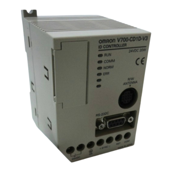
Page 26: Controller
Controller Section Controller 2-1-1 Nomenclature V700-CD1D-V3 1 Node Number Switches 2 DIP Switches 3 Indicators 4 Cover 5 Programming Console Port 6 Antenna Port 7 RS-232C Port 8 Power Supply and Ground Terminals 9 SYNC Terminals 10 RESET terminals V700-CD2D-V3... - Page 27 Open the cover only when necessary. through SW4 and the Programming Console port Programming Connecting to the OMRON’s C200H-PRO27-E Programming Console (sold Console port Programming separately) can be connected through the V700-P10 Programming Console Console Conversion Cable (sold separately). The V700-P10 is provided with a dedicated key sheet used for the operation of the Programming Console.
-
Page 28: Specifications
Controller Section 2-1-2 Specifications General Specifications Item Specification +10% Supply voltage 24 VDC –15% Power consumption 20 W max. including the power consumption of the Antenna (1.1 A at 12 V) and the Programming Console (150 mA at 5 V) Insulation resistance 20 MΩ... -
Page 29: Circuit Configuration
Controller Section Circuit Configuration Controller Another Controller Terminating resistance Positive Positive terminal terminal Negative Negative terminal terminal Another Controller CAUTION The positive SYNC or negative SYNC terminal is not an RS-485 terminal. Do not connect anything other than coaxial cables to these terminals. -
Page 30: Wiring Example
Controller Section Wiring Example V700-Hjj Antenna V700-P10 Programming Console Conversion Cable C200H-PRO27-E Programming Console Host PC V700-A4j Antenna Cable V700-CD1D-V3 Controller V700-CD1D-V3 24-VDC power supply – Another Controller Shielded wire –... -
Page 31: Antenna
Antenna Section 2-1-3 Dimensions V700-CD1D-V3 Two, 4.5 dia. Two, M4 Casing material: PC/ASA resin Antenna 2-2-1 Specifications Model Item V700-H01 V700-H02 Oscillation frequency 125 kHz Ambient operating temperature –20°C to 55°C (with no icing) Ambient storage temperature –35°C to 65°C (with no icing) -
Page 32: Dimensions
Antenna Section CAUTION The Connector is not water-resistant. Make sure that the connector is free of water. 2-2-2 Dimensions V700-H01 185±0.2 235±0.2 Four, 5 dia. mounting holes. 20 max. 16 max. Casing material PC/ASA resin Rear panel material Phenol resin Cable... - Page 33 Antenna Section V700-H02 185±0.2 635±0.2 Four, 5 dia. mounting holes. 20 max. 16 max. Casing material PC/ASA resin Rear panel material Phenol resin Cable...
-
Page 34: Id Tag
ID Tag Section ID Tag 2-3-1 Specifications Model Item V700-D23P31 V700-D23P41 Memory capacity User area: 240 bytes Type of memory EEPROM (non-volatile memory) Data backup time 10 years Data writing times 100,000 times per address Communications error Bilateral use of CRC (Cyclic Redundancy Check) 16 bits detection Ambient operating Communicating: –20°C to 70°C (with no... -
Page 35: Dimensions
ID Tag Section 2-3-2 Dimensions V700-D23P31 2.7±0.1 16 dia. ±0.1 20 dia. ±0.1 V700-D23P41 JAPAN 0249 3.9±0.1 dia. V700-D23P41 R0.25... -
Page 36: Memory Map
ID Tag Section 2-3-3 Memory Map The V700-D23P31 has a memory area of 240 bytes, and the V700-D13P21 has a memory area of 112 bytes. One-byte data can be written to a single address. An eight-byte block of memory area is treated as one page. Address Data One byte... -
Page 37: Cable
Cable Section 2-3-4 V700-A80 Attachment (For V700-DjjP31) This is a special Attachment for fastening a coin-shaped ID Tag to a workpiece. It can be used with V700-DjjP31 models. Mounting Hole Dimensions External Dimensions Two, M3 Two, 6 dia. 31±0.2 31±0.2 Two, 3.5 dia. -
Page 38: External Communications Specifications
V700 Communications Specifications Section 2-4-2 Dimensions V700-P10 Model V700-P10 Length Approx. 2 m Weight Approx. 110 g 2,000±100 Connector (Programming Console side) Connector (Controller side) V700-A4j Model Item V700-A40 V700-A41 V700-A42 V700-A43 V700-A44 V700-A45 Length Approx. 2 m Approx. 3 m Approx. - Page 39 Vertical parity (even, odd, or none) Horizontal parity as BCC Cable length 15 m max. Suitable connector D-sub 9-pin male connector OMRON XM2A-0901 Plug and XM2S-0911 Hood provided with the Controller Recommended cable Hitachi Cable CO-MA-VV-SB 5Px28AWG V700-CD2D-V3 Item Specifications...
-
Page 41: Functions
SECTION 3 Functions This section provides the modes and functions in detail. Single, FIFO Read/Write, and Multiple, Simultaneous Access Functions ... . . Write Protect Function ........... . . Memory Check Function . -
Page 42: Single, Fifo Read/Write, And Multiple, Simultaneous Access Functions
Single, FIFO Read/Write, and Multiple, Simultaneous Access Functions Section Single, FIFO Read/Write, and Multiple, Simultaneous Access Functions Three communication modes are available depending on the number or state of Tags in the communication area. Commands can be used for selecting one of them. -
Page 43: Write Protect Function
Memory Check Function Section Note In FIFO read/write mode, make sure that multiple ID Tags do not arrive in the communications area together, otherwise a communications error will result and further communications will not be possible until there is only a single ID Tag in the communications area. -
Page 44: Mutual Interference Preventive Function (Synchronous Function)
Mutual Interference Preventive Function (Synchronous Function) Section response code 75, which indicates normal data transmission, is returned. If they do not coincide, response code 76 is returned as a warning. Address First address of the area Check code calculation area (Number of check block bytes: 2) CRC (left digit) Check code area (two bytes) - Page 45 Mutual Interference Preventive Function (Synchronous Function) Section Wiring, and 8-6 Mutual Interference of Antenna for the settings, cable connec- tions, and mutual interference distance in detail. Total distance 300 m max. Master Slave 1 Slave 2 Slave 31 Switch settings Switch settings Switch settings Switch settings...
-
Page 46: Energy-Saving Mode
Long-distance Mode and Stable Communications Mode Section Energy-saving Mode The RFID System can be set to energy-saving mode. In case commands can be issued only during communications, the Antenna power can be shut down to reduce the total power consumption of the RFID Sys- tem. -
Page 47: Noise Environment Measurement Function
Error Logging Function Section Mode Item Long-distance mode Stable communications mode Antenna’s signal reception Low or high (automatically Always low amplification factor selectable) Communications distance Very long distance Long distance Environmental noise Affected easily Not affected easily interference Note Environmental noise can be easily checked with the Programming Console. Re- fer to 3-7 Noise Environment Measurement Function. -
Page 49: Setting, Mounting, And Connection Methods
............4-1-6 Connection of RS-232C Interface (V700-CD1D-V3) ..... . -
Page 50: Controller
Controller Section Controller 4-1-1 Switch Settings Open the cover of the Controller to make switch settings. Opening the Cover A screwdriver is provided with the Controller. Open the cover by inserting the screwdriver into the groove on the left side of the cover. Under the cover, there are two node number switches (SW1 and SW2), two DIP switches (SW3 and SW4), and a port to connect the Programming Console. - Page 51 Controller Section Settings Use the provided screwdriver to make switch settings as shown below. Node Number Settings DIP Switch Settings Default Set Values The following table shows default set values. Name Default set Meaning value Node number 00 Node number (10’s digit) Node number (1’s digit) SW3-1 System reserved pin...
- Page 52 Controller Section Node Number Settings Node Number If more than one Controller is connected to a single host through Link Adapters, each Controller needs an ID number so that the host can discriminate each of them. Such an ID number is called node number. Each Controller must have a unique node number.
-
Page 53: Dip Switch Settings
Controller Section DIP Switch Settings Pin 1: Communications Format Setting (V700-CD1D-V3/CD2D-V3 Only) This pin can be used to enable or disable BCC for the command and response format between the host and the Controller. When BCC is enabled, checking for communication errors between the host and Controller, resulting from factors such as noise, is executed using horizontal parity. - Page 54 Then if the value of noise reads more than 30, it is recommended that the Controller be used in stable communications mode. Pin 7 (V700-CD1D-V3): Not used Do not use this pin. Always set this pin to OFF. Pin 7 (V700-CD2D-V3): RS-485 Terminating Resistance...
-
Page 55: Installation Environment
Controller Section Pin 3: Data Length Setting Pin 3 Description 8 bits (JIS 8 bits) 7 bits (ASCII 7 bits) Pins 4 and 5: Parity Bit Setting Pin 4 Pin 5 Description (Even parity) Odd parity No parity Even parity Pin 6: Stop Bit Length Setting Pin 6 Description... -
Page 56: Mounting
Controller Section connected to the Controller are not affected by the noise of power lines or high- tension lines. Note Be sure to abide by the above before installing the Controller and carefully test the Controller. 4-1-3 Mounting The Controller can be mounted to DIN tracks or enclosed-mounted to panels with screws. -
Page 57: Connection And Disconnection Of Antenna Connector
(1) Hook the Controller to part A. Then press the Controller in direction B DIN track (1 m long) to mount the Controller. OMRON PFP-100N2 is recommended. (2) Pull the mounting hook down- wards. Then lift the Controller up- wards to disconnect the Controller. - Page 58 Controller Section Connection of Antenna Connector Connection Cable connector 1, 2, 3... 1. Hold and insert the connector into the port so that the point marked in black on the panel of the Controller coincides with the point marked in white on the connector.
-
Page 59: Wiring
Controller Section 4-1-5 Wiring Wire the Controller as shown below. Power Supply and Ground Wires Connection example Line filter +24 VDC Ferrite core (provided) Ground at a resistance of less than 100 Ω. The power supply and ground terminals use M3 set screws. The following type of solderless terminals can be connected to these terminals. - Page 60 Model Output Input voltage DC Power Supply S82K-03024 24 VDC 1.3 A 110/240 V (OMRON) S82J-0224 24 VDC 1.1 A 110 V S82H-10024 24 VDC 4.6 A 110/240 V The maximum power consumption of the Controller is 20 W (i.e., 0.8 A at 24 VDC).
- Page 61 Controller Section • Use the provided ferrite core for the suppression of noise generation as shown below. 1, 2, 3... 1. Wire the power supply and ground wires. 2. Wind the power supply and ground wires together around the ferrite core once so that the ferrite core will not move as shown below.
- Page 62 Controller Section Wiring RESET Signal RESET 24 VDC input I/O Solderless Terminal The I/O terminals use M3 set screws. The following type of solderless terminal can be connected to these terminals 6.5 max. Tighten each screw to a torque of approximately 6 kgf S cm. Note 1.
-
Page 63: Connection Of Rs-232C Interface (V700-Cd1D-V3)
Then secure the solderless terminals with the screw. Overlap the flat parts. Note The SYNC line can be extended up to a total of 300 m. 4-1-6 Connection of RS-232C Interface (V700-CD1D-V3) Signal direction Signal name Symbol... - Page 64 Controller Connecting device PC98 or compatible 9-pin male Cables with connectors 25-pin male Shield Shielded wire Connecting to OMRON C200H PC Connector Pin Arrangement when Viewed from the Controller Controller Connecting device RS-232C port 9-pin male Cables with connectors 9-pin male...
- Page 65 Controller Section Assembly and Connection of Communications Connector An OMRON communications connector conforming to EMI standards is pro- vided with the Controller. Use this communications connector or an equivalent one. Prepare a connection cable and a connector for the host computer. Refer to Ap- pendix B Ordering Information for details.
- Page 66 Controller Section 3. Attach housing A2 of the Hood to the Plug and secure the aluminum-taped portion with the cable clamp and two screws. Two, M2.6 lock screw Housing A2 Housing B2 Cable clamp 4. Put on housing B2 to complete the connector assembly. Connection and Disconnection of Connector •...
-
Page 67: Interface Connection (V700-Cd2D-V3)
Controller Section 4-1-7 RS-485 Interface Connection (V700-CD2D-V3) Terminal No. Polarity – – 2 3 4 Note Terminals 1 and 3, and terminals 2 and 4, Terminal No. are short-circuited in the RS-485 Controller. 1:N Connection Host RS-485 Controller 0 220-Ω terminating 220-Ω... - Page 68 Controller Section 1:N Connection Total distance: 300 m max. SW3, pin7: SW3, pin7: SW3, pin7: SW3, pin7: Terminating Terminating Terminating Terminating resistance ON resistance OFF resistance OFF resistance OFF – – – – Host terminating resistance ON Total distance: 300 m max. SW3, pin7: SW3, pin7: SW3, pin7:...
- Page 69 Controller Section Connecting and Disconnecting the Connector 1, 2, 3... 1. Attach crimp terminals to the ends of the cables with the insulating covering removed. While paying attention to the direction the connector is facing, in- sert the cables into the holes. (Use the connector that is provided.) To order connectors, contact Nihon Weidmiiller Co., Ltd.
-
Page 70: Installation Of Antenna
Installation of Antenna Section low) with a shaft of uniform thickness. If an ordinary screwdriver that nar- rows toward the tip is used, it will not fit all the way in. OMRON XW4Z-00C Screwdriver Side Front 3.5 mm 0.6 mm... -
Page 71: Countermeasures Against Noise
Installation of Antenna Section • The ambient temperature is not within a range between –20°C and 55°C or locations with radical temperature changes resulting in condensation. • The humidity is not within a range between 35% and 80%. • There is corrosive gas, flammable gas, dust, salt, or metal powder. •... -
Page 72: Id Tag
ID Tag Section ID Tag 4-3-1 Installation Environment Do not install the V700-D23P31 or V700-D13P21 ID Tag in the following loca- tion. • There is corrosive gas, flammable gas, dust, or metal powder. Do not install the V700-D13P21 ID Tag in the following locations. •... - Page 73 ID Tag Section strength. Check the materials in advance, and contact the maker for details on adhesive characteristics. V700-D23P41 ID Tag Mounting If the ID Tag is mounted with the rounder surface facing the Antenna, as shown in Direction the following diagram, the communications distance will be increased. If the ID Tag is faced in the opposite direction, the communications distance will be de- creased by approximately 10 mm.
-
Page 75: Communications Functions
SECTION 5 Communications Functions This section provides the communications functions and provides details on communications-related data and commands. Commands and Responses ..........Movement of ID Tag and Command . -
Page 76: Commands And Responses
Commands and Responses Section Commands and Responses In order to communicate with the ID Tag in the communications area of the An- tenna, commands must be selected and used according to the mode and move- ment of the ID Tag. ID Tags in Communications Area ID Tags operate in single mode, FIFO read/write mode, or multiple, simulta- neous access mode according to the number and provided conditions of ID Tags... -
Page 77: Movement Of Id Tag And Command
Communications Operating Sequence Section Multiple, Simultaneous In this mode, communications with all ID Tags in the communications area can Access Mode be made on receipt of the command. Note In FIFO read/write mode, make sure that multiple ID Tags do not arrive in the communications area together, otherwise a communications error will result and further communications will not be possible until there is only a single ID Tag in the communications area. -
Page 78: Single Trigger Mode
Communications Operating Sequence Section 5-3-1 Single Trigger Mode In this mode, the Controller communicates with the ID Tag in the communica- tions area provided that the ID Tag is not moving. Therefore, it is necessary to check that the ID Tag is at a standstill in the communications area. If the ID Tag is not in the communications area, an error response is returned. -
Page 79: Single Automatic Mode
Communications Operating Sequence Section 5-3-2 Single Automatic Mode In this mode, the Controller waits for the ID Tag to approach the Antenna com- munications area, and then communicates with the ID Tag. Host Controller ID Tag AUTO command Awaiting ID Tag Not approaching Awaiting ID Tag Not approaching... - Page 80 Communications Operating Sequence Section Controller is stopped or reset, the Controller is ready to receive the next com- mand. Host Controller REPEAT command Awaiting ID Tag Not approaching Not approaching Awaiting ID Tag (Awaiting response) Communications Tag (1) processing Response Response received Awaiting ID Tag...
-
Page 81: Polling Auto Mode
Communications Operating Sequence Section 6. After the data is processed, the Controller returns a response to the host in- dicating that the Controller is finished with data processing. Note In order to send the next command while the Controller is in repeat mode, be sure to execute the STOP or RESET command so that the Controller will stop processing the current command and be ready to receive the next command. -
Page 82: Multi-Trigger And Multi-Repeat Modes
Communications Operating Sequence Section 2. After the command is received, the Controller returns a response to the host indicating the acceptance of the command. 3. The host sends the POLLING AUTO command to node 2. 4. After the command is received, the Controller returns a response to the host indicating the acceptance of the command. - Page 83 Communications Operating Sequence Section the SPECIFY TAG command, which communicates with specific ID Tags based on the simple numbers that have been assigned. Controller Host DETECT TAG command Communications processing Tag (0) Response (including simple No. 0) Response received Communications processing Tag (1) Response (including simple No.
- Page 84 Communications Operating Sequence Section Note When using the selective access mode, set the Controller to energy-saving mode. Precautions when Using Selective Access Mode 1, 2, 3... 1. When using the selective access function, set pin 5 of the Controller’s switch 3 to ON and set the Controller to energy-saving mode.
-
Page 85: Command And Response Frame Structure
Command and Response Frame Structure Section memory for 16 of them and not for the others. The Controller, however, re- turns a response to the host for all of the ID Tags, with “X” indicated instead of the simple number for all of the ID Tags exceeding 16. If X is specified in a SPECIFY TAG command, the Controller returns a command error to the host. - Page 86 Command and Response Frame Structure Section BCC Enabled Node number Text “jj” BCC Disabled Node number Text “jj” Name Description This code indicates the beginning of a communications frame. This code is 02h in ASCII. Node number This indicates the node number of the Controller that can be set within a range between 00 and 31 (decimal) on the rotary switches of the of the Controller.
-
Page 87: Command List
Command List Section Name Description Retry Flag The Retry Flag is set to 0 if ACK OR NACK control is not used. The Retry Flag is set to 1 and the previous response is returned if no ACK is received within a specified time in ACK/NACK control. -
Page 88: List Of Options
Data Code Designation Section List of Options The following eight options can be placed in the READ, WRITE, ADD, and SUB- TRACT command frame structure to specify communications according to the number of ID Tags in the communications area, their conditions, the movement of the ID Tags, and the operating status of the Controller. -
Page 89: Hex Code Designation: H
Data Code Designation Section Writing Example If “OMRON” is written to the five bytes beginning with address 10h in the memory, the addresses will be occupied with the following data. Command Number of Communica- Command ASCII Antenna First address Write data... -
Page 90: Example Of Bcc Calculation
Data Code Designation Section Command code Designation range of Designation range of bytes first address READ 00h to EFh ASCII code 01h to F0h HEX code 01h to 80h WRITE 00h to EFh ASCII code 01h to F0h HEX code 01h to 80h 00h to EFh 01h to 08h... -
Page 91: Explanation Of Commands And Responses
ACK/NACK Control Section Explanation of Commands and Responses The transmission of a command from the host to the Controller or the transmis- sion of a response from the Controller to the host varies with the type of com- mand and the difference in communications designation. No Response When the Controller receives the RESET command, the Controller is reset with- out returning a response and waits for the next command. -
Page 92: Communications Commands
Communications Commands Section 5-10 The host does not send ACK/NACK within a preset time-out period. Host Command Controller Response Response Time out Retry 5-10 Communications Commands 5-10-1 READ: RD Reads data from a Tag. Command Frame Structure Command Node No. Commu- Data Chan-... -
Page 93: Write: Wt
Communications Commands Section 5-10 5-10-2 WRITE: WT Writes data to a Tag. Command Frame Structure Command Node No. Commu- Data Chan- First write No. of Write data ETX BCC code nications type address write bytes Specified quantity Communications Specify the communications method with the Tag. ST: Single trigger SA: Single auto SR: Single repeat... -
Page 94: Add: Ad
Communications Commands Section 5-10 5-10-3 ADD: AD The data in the memory of the ID Tag is treated as hexadecimal data, to which AD data is added. Command Frame Structure Command Node No. Commu- Chan- First address No. of bytes in Add data ETX BCC code... -
Page 95: Subtract: Sb
Communications Commands Section 5-10 5-10-4 SUBTRACT: SB The data in the memory of the ID Tag is treated as hexadecimal data, to which SB data is subtracted. Command Frame Structure Command Node No. Commu- Chan- First address No. of bytes in Subtract data ETX BCC code... -
Page 96: Polling Autoread: Pr
Communications Commands Section 5-10 5-10-5 POLLING AUTOREAD: PR When the host sends POLLING AUTOREAD command to the Controller, the Controller immediately returns a response to the host indicating the acceptance of the command. Then the Controller waits for the approaching ID Tag and reads the data of the ID Tag when the ID Tag is in the communications area of the An- tenna. -
Page 97: Polling Autowrite: Pw
Communications Commands Section 5-10 5-10-6 POLLING AUTOWRITE: PW When the host sends POLLING AUTOWRITE command to the Controller, the Controller immediately returns a response to the host indicating the acceptance of the command. Then the Controller waits for the approaching ID Tag and writes data to the ID Tag. -
Page 98: Memory Calculate: Mk
Communications Commands Section 5-10 Response Frame Structure Command Response Node No. Retry ETX BCC code code Flag Response code 75: The comparison results are correct. 76: The comparison results are not correct. Refer to 5-16 List of Response Codes for other response codes. Note Make sure that the specified data is within the memory capacity of the ID Tag. - Page 99 Communications Commands Section 5-10 • Example of Command Execution In the following example, the data in address 10h to 12h is checked. Address First address of the area Check code calculation area Number of check (Number of check block bytes: 2) block bytes CRC (left digit) Check code area (two bytes)
-
Page 100: Write Protect: Wp
Communications Commands Section 5-10 4. If the data does not coincide, MC76 (a data error warning) will be returned. Data error 5-10-9 WRITE PROTECT: WP Sets and releases write protection by page. Command Frame Structure Command Node No. Chan- Protection setting Protection release code information... - Page 101 Communications Commands Section 5-10 Example of Write Protection Setting and Releasing The following is an example of command execution and responses for setting write protection on pages 1 and 6 and releasing write protection on pages 5 and 8 of the ID Tag, provided that pages 2, 5, 8, and 13 the ID Tag are set to write protection.
-
Page 102: Communications Subcommands
Communications Subcommands Section 5-11 5-11 Communications Subcommands 5-11-1 POLLING CHECK: PC This subcommand is used after sending the POLLING AUTO command to check the results of the execution of the POLLING command. Command Frame Structure Command Node No. Chan- ETX BCC code Channel Always 1. -
Page 103: Control Commands
Control Commands Section 5-12 Response Frame The following frame structures are used for the response after completing com- Structure munications with the ID Tag and before completing communications with the ID Tag. 1, 2, 3... 1. Before Completion of Communications with Tag Command Response Node No. -
Page 104: Host Command
Host Subcommands Section 5-14 5-13 Host Command 5-13-1 TEST: TS This command returns test messages sent from the host without changing any- thing. The test command is used for communications tests between the host and Controller. Command Frame Structure Command Test message ETX BCC Node No. -
Page 105: Other Command
Response Codes Section 5-16 5-15 Other Command 5-15-1 Undefined Command Response If the Controller receives an undefined command, the Controller will return a re- sponse for the undefined command to the host. Response Frame Structure Command Node No. code 5-16 Response Codes The response codes are described in the following table. -
Page 106: Connecting Commands
Connecting Commands Section 5-17 5-17 Connecting Commands The Controller can use a connecting command function to send only one com- mand to the ID Tag to read and write data from and to the ID Tag. Available Commands Any pair of the following nine commands can be used. •... -
Page 107: Communications Programming Example
1, the Controller will perform polling processing. 5-18 Communications Programming Example BASIC Programming The following is an example of a program for operating the V700-CD1D-V3. Example ’***** V700–CD1D SAMPLE PROGRAM ***** OPEN ”COM:E73NN” AS #1 RECV$=””:SREC=0... -
Page 109: Programming Console
SECTION 6 Programming Console This section provides the installation and use of the Programming Console in relation to the V700 System. Introduction ............. Nomenclature . -
Page 110: Introduction
External Dimensions Section Introduction OMRON’s C200H-PRO27-E Programming Console connects to the V700-CD1D Controller through the V700-P10 Programming Console Conver- sion Cable, thus making it possible to test the communications between the Controller and ID Tags when starting up the system. Furthermore, the Program-... -
Page 111: Connecting The Programming Console
Connecting the Programming Console Section Connecting the Programming Console The Programming Console can be connected to the Controller through the V700-P10 Programming Console Conversion Cable (sold separately). The V700-P10 is provided with a keysheet. 6-4-1 Insertion of Keysheet As shown in the following illustration, insert the provided keysheet into the inser- tion slot. - Page 112 Connecting the Programming Console Section 1, 2, 3... 1. Remove the rear-upper cover or rear connector cover of the Programming Console. Be careful not to misplace the removed cover. 2. Connect the square connector to the Programming Console. Press in the square connector securely until the lock lever clicks.
-
Page 113: Operation
Operation Section Operation Hand-held Operation Panel Mounting Use the C200H-ATT01 (sold separately) for the panel mounting of the Program- ming Console. Mounting Dimensions Bracket The following standard mounting dimensions Two screws conform to DIN43700. Space of approximately 50 mm is required. Use either one of +1.1 the connectors. -
Page 114: Functions
Functions Section 2. The mode selection key can be pulled out in the RUN or MONITOR position but not in the PROGRAM position. × f: Key can be pulled out. ×: Key cannot be pulled out. 3. The V700-series Controller does not operate in PROGRAM mode. Do not set the key to PROGRAM. -
Page 115: Functions Of The Programming Console
Functions Section 6-6-1 Functions of the Programming Console MONITOR mode Set data Read and write data Read Write Execute TEST Communications READ test Execute TEST READ Ambient noise check Latest error log Statistical error log RUN mode Set data Operation PROGRAM mode MONITOR Mode •... -
Page 116: Operation Procedure
Functions Section 6-6-2 Operation Procedure Password Input Display The following display will appear when the Programming Console is connected. Press the RESET Key and then SET Key. Then the default state of the operation mode is displayed. If the password is entered while the Controller is in MONITOR mode, the Con- troller in operation will be interrupted. - Page 117 Functions Section Key Input in Default The default display in MONITOR mode appears by setting the key switch to Display of MONITOR MONITOR. The READ, WRITE, TEST READ, TEST WRITE, NOISE CHECK, Mode LAT.ERR INFO, STA. ERR INFO, and SET INFO Keys will be available. No other keys will be available.
-
Page 118: Set Data Display
Functions Section 6-6-3 Set Data Display Data that is set with the DIP switch of the Controller is displayed item by item. Displays the node number. Displays the RS-232C setting. Displays the ACK/NACK control setting. Displays the synchronous setting. Displays the energy-saving setting. -
Page 119: Address Setting
Functions Section 6-6-4 Address Setting Set the start address and end address to determine the area where data is to be read, written, or tests conducted. Read Data In the following example, the start address is set to 5Ah and the end address is set to 6Fh. -
Page 120: Data Setting
Functions Section 6-6-5 Data Setting Set the write data in two digits within a range between 00 and FF in hexadecimal. In the following example, the data is set to 1B. By pressing the DATA Key, the Programming Console is ready to accept address input. The 0 through 9 and the A through F Keys are available. - Page 121 Functions Section Read Retry After the data is read from the ID Tag, by pressing the SET Key again, the data between the present start address and end address is read gain. By pressing the INC or DEC Key, the start address and end address increase or decrease by 1 each and the corresponding data is read.
-
Page 122: Test
Functions Section Write Retry After the data is written to the ID Tag, by pressing the SET Key again, the data between the present start address and end address is written to the ID Tag again. By pressing the INC or DEC Key, the start address and end address in- crease or decrease by 1 each and the corresponding data is written. -
Page 123: Ambient Noise Check
Functions Section Test Read Set the communications mode to single trigger mode. Set the start address and end address. Press the SET Key. Then the number of retries and the data of the ID Tag are displayed. Test Write Set the communications mode to FIFO repeat mode. -
Page 124: Reading Latest Error Log
Functions Section 6-6-9 Reading Latest Error Log After the Controller is turned ON, the Controller will keep a record of up to 30 errors in RUN mode if such errors result. If another error results, the Controller will keep it on record by deleting the oldest one from the record, thus always keeping the latest 30 errors. -
Page 125: Statistical Error Log
Functions Section 6-6-10 Statistical Error Log The Controller classifies all errors recorded after the Controller starts operating according to the response code and displays the number of each type of errors. At the same time, the Controller performs MCBF (i.e., the total number of host commands divided by the total number of errors recorded) calculation. -
Page 127: Startup And Full Operation
SECTION 7 Startup and Full Operation This section provides information on trial operation, errors and remedies, and maintenance and troubleshooting. Trial Operation ............Self-diagnostic Function . -
Page 128: Trial Operation
Trial Operation Section Trial Operation Check Items Check the following on the RD-ID System before the trial operation of the whole system. Items Detail Page • Are the power supply and I/O lines properly Power supply and I/O lines wired? •... -
Page 129: Self-Diagnostic Function
List of Errors Section Self-diagnostic Function The Controller has a self-diagnostic function to check a variety of items in order to reduce the downtime of the system that may result due to operational failures. If an error results, the details of the error may be read through the Programming Console. -
Page 130: Errors And Remedies
Errors and Remedies Section Communications Error between Controller and ID Tag Response Name Error message Meaning code Communications error COM.DC E An error occurred during communications between the Controller and ID Tag. • There was a setting mistake in the passing speed or sens- ing distance of ID Tag. -
Page 131: Maintenance And Inspection
Maintenance and Inspection Section Noise Interference If the system malfunctions due to noise, refer to the following and take appropri- ate countermeasures. Circumstance of failure Probably cause Remedy Occurs when a An instantaneous voltage drop due Increase the capacity of the power supply and that of heavy-duty motor, ea y du y o o ,... - Page 132 Maintenance and Inspection Section Inspection Items Item Detail Criteria Remarks Supply voltage fluctuation Check that the supply voltage Supply voltage rating Multimeter fluctuation at the power supply terminal block is within the permissible range. Check that there is no frequent Within permissible voltage Power supply instantaneous power failures or...
-
Page 133: Troubleshooting
Troubleshooting Section Troubleshooting If an error results, fully check the whole situation, determine the relationship be- tween the system and any other device, and refer to the following flowcharts for troubleshooting. Main Check Flowchart Use the following main check flowchart to determine the cause of the error. Main check flowchart Go to the system connections Are all devices in the system... - Page 134 Troubleshooting Section System Connections Check Flowchart Start Are the connected connectors and cables Connect them normally. Turn power ON. Is the RUN indicator ON? Is the rated voltage provided? Provide the rated voltage. Is RESET input ON? Turn RESET input OFF. Is the ERROR indicator ON? Is the sync...
- Page 135 Troubleshooting Section Host Communications Check Flowchart Start Send the TS command from the host. Is the response normal? Is the communications frame OK? Revise the communications frame correctly. Are the communications cable connectors wired OK? Wire the connectors correctly. Is the host working normally? Revise the host program correctly or replace the host.
- Page 136 Troubleshooting Section Communications Check Flowchart Start Can the Programming Console be used? Connect the Programming Do not connect the Programming Console and turn ON the Console and turn ON the Controller in MONITOR mode. Controller and connect the host. Execute the TEST WRITE Send the WRITE command command in single auto in single auto mode.
- Page 137 Troubleshooting Section Operating Environment Check Flowchart Start Refer to 7-5 Maintenance Are the operating and Inspection. conditions OK? Is the ambient Refer to 7-4 Errors and noise OK? Remedies.
-
Page 139: Reference Data
SECTION 8 Reference Data This section provides reference data relating to V700 communications, ID Tags, Antennas, and proximity sensors. Maximum Communications Distance ......... Communications Distance Characteristics vs. -
Page 140: Maximum Communications Distance
Maximum Communications Distance Section Maximum Communications Distance The maximum communications distance varies with the installation and envi- ronmental conditions. Be sure to check the required conditions carefully. Maximum Antenna ID Tag Communications V700-H01 V700-H02 Distance in Long-distance Mode V700-D23P31 Max. communications distance 250 mm (typ) 280 mm (typ) Recommended... -
Page 141: Communications Distance Characteristics Vs. Ambient Noise
Communications Distance Characteristics vs. Ambient Noise Section Communications Distance Characteristics vs. Ambient Noise The communications distance characteristics may deteriorate due to the ambi- ent noise at the Antenna location. Before installing the Antenna, use the noise check function, measure the noise level in the installation environment, and set the communications distance by referring to the following. - Page 142 Communications Distance Characteristics vs. Ambient Noise Section V700-H01 (V700-D23P41) Long-distance mode Stable communications mode Noise level (read by the Programming Console) V700-H02 (V700-D23P41) Long-distance mode Stable communications mode Noise level (read by the Programming Console)
-
Page 143: Communications Areas
Communications Areas Section Communications Areas Communications Areas in Long-distance Mode V700-H01 (V700-D23P31) The following is the planer communications area of the V700-H01 when the Tag passes through the center of the Antenna and perpendicular to the Antenna sur- face. 25 cm max. V700-H01 Unit: cm V700-H02 (V700-D23P31) - Page 144 Communications Areas Section Communications Areas in Stable Communications Mode V700-H01 (V700-D23P31) The following is the planer communications area of the V700-H01 when the Tag passes through the center of the Antenna and perpendicular to the Antenna sur- face. 20 cm max. V700-H01 V700-H02 (V700-D23P31) The following are the communications areas of the V700-H02 in the X and Y...
- Page 145 Communications Areas Section Communications Areas in Long-distance Mode V700-H01 (V700-D23P41) The following is the planer communications area of the V700-H01 when the Tag passes through the center of the Antenna and perpendicular to the Antenna sur- face. V700-H01 X (cm) V700-H02 (V700-D23P41) The following are the communications areas of the V700-H02 in the X and Y directions.
- Page 146 Communications Areas Section Communications Areas in Stable Communications Mode V700-H01 (V700-D23P41) The following is the planer communications area of the V700-H01 when the Tag passes through the center of the Antenna and perpendicular to the Antenna sur- face. V700-H01 X (cm) V700-H02 (V700-D23P41) The following are the communications areas of the V700-H02 in the X and Y directions.
-
Page 147: Communications Time
Communications Time Section Communications Time The V700-series Controller reads or writes eight-byte data per page from or to addresses X0h through X7h or X8h through XFh. In order to minimize the com- munications time, therefore, specify the address and the number of bytes so as to minimize the number of pages. - Page 148 Communications Time Section Calculation Formula Operation Actual communications time (msec) Reading T = 46.7N +107.4 Note N: Number of pages processed Read/Write Sync Actual communications time (ms) Writing Writing Reading Reading Number of bytes processed Number of pages processed Calculation Formula Operation Actual communications time (msec)
-
Page 149: Influence Of Background Metal On Antenna
Influence of Background Metal on Antenna Section Influence of Background Metal on Antenna The Antenna is influenced by background metal. The communications area of the Antenna will be reduced if there is metal behind the Antenna as shown below. V700-H01 (V700-D23P31) V700-H01 Metal: Steel (SPCC) Long-distance mode... - Page 150 Influence of Background Metal on Antenna Section V700-H02 (V700-D23P31) V700-H02 Metal: Steel (SPCC) Long-distance mode Stable communications mode Distance between background metal and Antenna V700-H02 Metal: Aluminum Long-distance mode Stable communications mode Distance between background metal and Antenna Metal Antenna Distance Communications between the...
- Page 151 Influence of Background Metal on Antenna Section V700-H01 (V700-D23P41) V700-H01 V700-H01 Metal: Steel (SPCC) Metal: Aluminum Long-distance Long-distance mode mode Stable Stable communications communications mode mode 200 250 300 200 250 300 Distance between background metal and Antenna (mm) Distance between background metal and Antenna (mm) V700-H02 (V700-D23P41) V700-H02 V700-H02...
-
Page 152: Mutual Interference Between Antennas
Mutual Interference between Antennas Section Mutual Interference between Antennas If more than one Antenna is used, be sure to keep the Antennas away from each other as shown below. Synchronous Operation V700-H01 V700-H02 Located Face-to-face Located Face-to-face 1 m min. 1 m min. -
Page 153: Asynchronous Operation
Mutual Interference between Antennas Section Asynchronous Operation V700-H01 V700-H02 Located Face-to-face Located Face-to-face 18 m min. (12 m min.) 20 m min. (15 m min.) Located in Parallel Located in Parallel 15 m min. (10 m min.) 20 m min. (15 m min.) Values in parentheses are 20 m min. -
Page 154: Mutual Interference Between Proximity Sensor And Antenna
Mutual Interference between Proximity Sensor and Antenna Section Mutual Interference between Proximity Sensor and Antenna The V700 Series employs electromagnetic induction at a frequency of 125 kHz. Therefore, if the Antenna and proximity sensor are installed close to each other, the Antenna and proximity sensor may malfunction due to mutual interference. -
Page 155: Influence Of Background Metal On Id Tag
Influence of Background Metal on ID Tag Section Influence of Background Metal on ID Tag The ID Tag is influenced by background metal. The communications distance of the ID Tag will decrease if there is metal behind the ID Tag as shown below. V700-H01 (V700-D23P31) V700-H01 Metal: Steel (SPCC) - Page 156 Influence of Background Metal on ID Tag Section V700-H02 (V700-D23P31) V700-H02 Metal: Steel (SPCC) Long-distance mode Stable communications mode Distance between background metal and Tag (mm) V700-H02 Metal: Aluminum Long-distance mode Stable communications mode Distance between background metal and Tag (mm) Antenna Metal Communications...
- Page 157 Influence of Background Metal on ID Tag Section V700-H01 (V700-D23P41) V700-H01 Metal: Steel (SPCC), Aluminum Long-distance mode Stable communications mode Distance between background metal and Tag (mm) V700-H02 (V700-D23P41) V700-H02 Metal: Steel (SPCC), Aluminum Long-distance mode Stable communications mode Distance between background metal and Tag (mm) Metal Antenna Distance be-...
-
Page 158: Influence Of Id Tag Incline
Influence of ID Tag Angle Section 8-10 Influence of ID Tag Incline When mounting an ID Tag, the maximum communications distance is obtained when the ID Tag surface is parallel with the Antenna surface. Therefore the influ- ence of ID Tag incline must be taken into account. If the ID Tag is mounted at an incline, the communications distance is shortened as shown in the tables below. -
Page 159: Chemical Resistance Of Id Tag
Chemical Resistance of ID Tag Section 8-11 Reduction of θ° Communications Distance 8-11 Chemical Resistance of ID Tag The V700-D23P31 ID Tag uses PPS resin. Refer to the following and be sure not to use any chemical that has a bad influence on PPS resin. Chemical Room 90°C... -
Page 160: Relationship Between Id Tag And Metal Sensor
Relationship between ID Tag and Metal Sensor Section 8-12 8-12 Relationship between ID Tag and Metal Sensor If a metal sensor is used for the detection of metal objects and each object is on a non-metal base attached with the V700-D23P31 or V700-D13P21 ID Tag, the ID Tag will not affect the metal sensor in sensing operation. -
Page 161: A Ascii Code
Appendix A ASCII Code Rightmost 4 bits b8 to b5 Leftmost 4 bits b4 to b1 Line Unde- fined Unde- fined Note The character in row 5, line 12 is “\” in ASCII. -
Page 163: Standard Models
Appendix B Standard Models Controller and System Components Name Specification Model Remarks Controller RS-232C interface V700-CD1D Supply voltage: 24 VDC Antenna External dimensions: 250 x 200 V700-H01 Standard antenna Antenna External dimensions: 650 x 200 V700-H02 Wide-field antenna 256-byte memory (240 bytes are V700-D23P31 Coin-shaped, ID Tag... -
Page 165: Index
Index V700, 20 communications areas, 125 ACK/NACK control, 73 Communications Connector, assembly, 47 Antenna dimensions, 14 Communications Distance Setting, 35 effect of nearby metal, 131 Communications Mode Setting, 37 installation, 52 interference between antennas, 134 Communications Sync Setting, 35 interference with Proximity Sensors, 136 specifications, 13 communications time, 129 Antenna Cable, 39... - Page 166 Index Parity Bit Setting, 37 ID Tag communications modes, 58 polling auto mode, 63 dimensions, 17 power consumption, reducing, 28 effect of nearby metal, 137 effects of chemicals, 141 Power supply terminals, 9 installation, 54 power supply terminals, 41 orientation, 140 precautions, general, xiii specifications, 16 Programming Console...
- Page 167 Index Stop Bit Length Setting, 37 subcommand set ACK, 86 NACK, 86 Time–out Setting, 37 POLLING CHECK, 84 POLLING END, 84 trial operation, 110 switch settings, 32 SYNC Signal, wiring, 44 trigger mode, 60 SYNC terminals, 9 circuit configuration, 11 troubleshooting, 115 synchronous function, 26 wiring, Controller, 12, 41...
-
Page 169: Revision History
Pages xviii, 2, 15, 16, 45, 69, 108, 121, 122, and 125: ID Tag model numbers changed. Pages 15 and 125: Memory capacity changed. Page 17: First sentence and graphic changed. April 2006 V700-CD1D changed to V700-CD1D-V3 and V700-CD2D-V3 added throughout the manual. V700-D23P21 changed to V700-D23P31 and V700-D23P41 added throughout the manual. - Page 172 OMRON ELECTRONICS LLC One Commerce Drive Schaumburg, IL 60173-5302 U.S.A. Tel: (1) 847-843-7900/Fax: (1) 847-843-7787 OMRON ASIA PACIFIC PTE. LTD. No. 438A Alexandra Road # 05-05/08 (Lobby 2), Alexandra Technopark, Singapore 119967 Tel: (65) 6835-3011/Fax: (65) 6835-2711 OMRON (CHINA) CO., LTD.
Need help?
Do you have a question about the V700-CD1D-V3 and is the answer not in the manual?
Questions and answers