Table of Contents
Advertisement
Quick Links
Original User's Manual
Installation, Setup, Operation and Maintenance
Geset 100
Article number of documentation 32708885
Copyright ©, Weber Marking Systems GmbH
Weber Marking Systems GmbH
Version: 16.07.13 /KRA
Maarweg 33
D-53619 Rheinbreitbach
E-Mail: info@webermarking.de
32708885
http://www.webermarking.de
Advertisement
Table of Contents

Related Manuals for Weber Geset 100

Summary of Contents for Weber Geset 100
- Page 1 Original User’s Manual Installation, Setup, Operation and Maintenance Geset 100 Article number of documentation 32708885 Copyright ©, Weber Marking Systems GmbH Weber Marking Systems GmbH Version: 16.07.13 /KRA Maarweg 33 D-53619 Rheinbreitbach E-Mail: info@webermarking.de 32708885 http://www.webermarking.de...
- Page 2 Blank page...
-
Page 3: Table Of Contents
Content 32708885 Geset 100 Table of content General information ....................6 Overview ........................... 6 Liability restrictions ......................6 Warranty provisions ......................6 Copyright ........................... 6 Purpose and overview of the operating instructions............7 How to use the operating instructions ................7 Service-Hotline ........................ - Page 4 Content 32708885 Geset 100 Requirements at the installation site .................... 32 Placing the labeling system ......................33 Setting up the labeling system ..................33 Connecting the labeling station ..................33 Connection to supply voltage ..................34 Safety instructions ........................34 Adjustment and initial operation ...............
- Page 5 Content 32708885 Geset 100 Safety instructions ........................72 Mechanical error ......................73 Correcting Adjustments based on labeler result .............. 74 Correct labeling ..........................74 Error at labeling ..........................74 11. Index ........................76 12. EC Declaration of conformity ................77 Version: 16.07.13...
-
Page 6: General Information
Any and all copying, photocopying, reproduction or translation of this document or parts thereof may only be done for personal use. Without prior written approval from Weber Marking Systems GmbH, this document may not be reproduced for the sake of third par- ties. -
Page 7: Purpose And Overview Of The Operating Instructions
32708885 Geset 100 Purpose and overview of the operating instructions These operating instructions will help you get to know the system Geset 100 and use it properly. They contain important instructions for the user on how to use the system safely and cor- rectly. -
Page 8: Service-Hotline
Chapter 1 General information 32708885 Geset 100 Service-Hotline The technical service hotline is available 24 hours a day, Monday through Friday. In emergencies, parts may be shipped as late as approximately 10:00 p.m. Tel : +49 (0)2224 - 7708 - 440... -
Page 9: Explanation Of The Terms Used
Chapter 1 General information 32708885 Geset 100 Explanation of the terms used Term Explanation Is used for labeling around of round products. 3-Roll System Drive for rotating or linear movements. Normally pneumatic Actuator (cylinder) or electromagnetic (motors). The air assist tube conducts the supporting air through one Air assist tube or more holes to the bottom of the label. - Page 10 Chapter 1 General information 32708885 Geset 100 Term Explanation The abbreviation of Height Processing Unit: A device that is driven by a motor or pneumatically to move a labeler verti- cally. This feature enables different labeling positions in vertical direction.
- Page 11 Chapter 1 General information 32708885 Geset 100 Term Explanation American unit measure compressed air. (1 PSI = 0.06895 bar). Metal plate about which the label is peeled off. Peeler plate Pushes the label onto the product strongly sticking. Pusher roller...
- Page 12 Chapter 1 General information 32708885 Geset 100 Term Explanation Direct current voltage See service unit Water trap Version: 16.07.13 Page 12 of 77...
-
Page 13: Safety Regulations
Chapter 2 Safety regulations 32708885 Geset 100 2. Safety regulations Behavior in an emergency The operating personnel must know the location of and how to use safety equipment, alarms, first aid and rescue equipment. What to do in an emergency? If individuals, body parts or objects become caught in the moving parts of the la- ¥... -
Page 14: Intended Use
Chapter 2 Safety regulations 32708885 Geset 100 Intended use The operational safety of the system Geset 100 is guaranteed only if it is used as inten- ded. Intended use consists of the following … The labeling system may only be used for automatically labeling moving and sta- ¥... -
Page 15: Reasonably Foreseeable Misuse
Chapter 2 Safety regulations 32708885 Geset 100 Reasonably foreseeable misuse Usage different than or going beyond that specified under "Intended use" is considered unauthorized. The operator bears sole responsibility for Damage arising from improper use. • Furthermore, the manufacturer assumes no liability for such use. -
Page 16: Hazards To The Labeling System
Chapter 2 Safety regulations 32708885 Geset 100 Hazards to the labeling system Fig. 2-1: Example for hazards to the labeling station Geset 114 Fig. 2-2: Example for hazards to the labeling station Geset 121 Version: 16.07.13 Page 16 of 77... -
Page 17: Safety Instructions
Chapter 2 Safety regulations 32708885 Geset 100 Following assembly groups may point out an entanglement or a crushing hazard f.l.t.r.: Top conveyor, • Wrapping unit, • Base conveyor • Labeler, • Guidances. • Possible injuries that may be caused by the assembly groups of the labeler, are normally reversible. - Page 18 Chapter 2 Safety regulations 32708885 Geset 100 Hazard from actively controlled movements. CRUSHING HAZARD! The movements of the labeling station are motor-driven by an automatic controller. - Maintain a distance from moving parts. Danger to health from the improper use of lubricants and cleaners.
-
Page 19: Remaining Risks
Chapter 2 Safety regulations 32708885 Geset 100 Remaining risks The labeler is constructed in a way that makes it safe for use. Some hazards are inherent in the design and construction but can be minimized with the corresponding safety mech- anisms and equipment. -
Page 20: Obligations Of The Operator
Qualified personnel are operators who … Have terminated a professional technical training (Electrician, Mechanist). ¥ Have terminated a training at the Bluhm- Weber-Group successfully. ¥ Qualified personnel are allowed… To arrange repair- and maintenance works at the labeling station and its compo- ¥... -
Page 21: Personal Protective Gear
Chapter 2 Safety regulations 32708885 Geset 100 Personal protective gear Wear the following protective gear when working on the machine: PROTECTIVE FOOTWEAR To protect against falling parts and slipping. PROTECTIVE WORK CLOTHES Protective work clothes fit snugly, tear easily, have tight-fitting sleeves and no projecting parts. -
Page 22: Protection Devices
Chapter 2 Safety regulations 32708885 Geset 100 Protection Devices Operate the system only if all safety- and protection devices are completely available and functional. Check the protection devices for its function: At first operation. ¥ At regular routine test. ¥... -
Page 23: Workplaces For The Operating Personnel
Chapter 2 Safety regulations 32708885 Geset 100 Workplaces for the operating personnel The labeling station is an automated system and does not require operation while label- ing. When the labeling system is operating without any malfunction, the operator may only be in the safe area, that is, the area covered by the protective measures. -
Page 24: Specifications
20 - 90 % relative humidity (non condensing) Surrounding conditions: Information on operator elements 1 illuminated pushbutton and 1 button, and 1 Pushbutton unit Geset 100 Emergency Stop Pushbutton Operator panel or display (s. Alpha’s manual) HMI Labeler Noise level The A-evaluated equivalent permanent noise level at the working places of this system is maximum 75db (A). -
Page 25: Description Of The Labeling Station
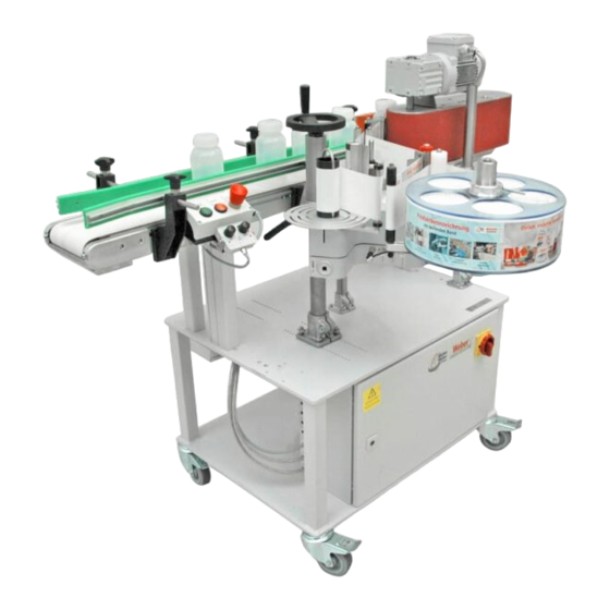
Chapter 4 Description of the labeling station 32708885 Geset 100 4. Description of the labeling station The labeling station Geset 114 is used to label square, cyclindrical, conical, oval as well as half-rounded products automatically. The labeling station Geset 121 is used to label round products automatically. -
Page 26: Complete Overview
Chapter 4 Description of the labeling station 32708885 Geset 100 Complete overview This figure shows the essential assembly parts of the Geset 114. Fig. 4-1: Overview of labeling station Geset 114 Description HEIGHT ADJUSTMENT TOP CONVEYOR TOP CONVEYOR WITH DRIVE... - Page 27 Chapter 4 Description of the labeling station 32708885 Geset 100 This figure shows the essential assembly parts of the Geset 121. Fig. 4-2: Overview of labeling station Geset 121 Description PUSHER PLATE (SPONGE RUBBER) WRAPPING UNIT WITH DRIVE SWITCH CABINET...
-
Page 28: Transport
- Stand to the side outside of the hazard zone. Hazard from falling parts. - Wear protective footwear. The transport will be arranged by a Technician of the Bluhm Weber Group or by authori- zed specialists. Version: 16.07.13 Page 28 of 77... - Page 29 Chapter 5 Transport 32708885 Geset 100 Remove the packaging material and the transport securing de- vices only at the site of use, and transport the labeling system in its original packaging to the labeling site. If the labeling system is not secured, it can tip over easily when transported.
- Page 30 Chapter 5 Transport 32708885 Geset 100 Instruction Use the following procedure to transport the labeling system to its site of use. Step Procedure Transport the labeling system to its site of use (within 3 m). The labeling system is precisely positioned during installation by a Technician from the Bluhm Weber Group.
-
Page 31: Storage Conditions
Chapter 5 Transport 32708885 Geset 100 Storage conditions The conditions for storing a labeling system are the same as those of normal operation. For details see the chapter: "Specifications" on page 24. Instruction Store the labeling system securely as follows. -
Page 32: Installation And Initial Startup
This required professional knowledge cannot be completely communicated by the operat- ing instructions; therefore a Technician from the Bluhm Weber Group needs to perform the installation or accept the labeling system in a final inspection. The warranty does not cover damage or consequential damage arising from improper installation lacking the necessary fine adjustments. -
Page 33: Placing The Labeling System
Chapter 6 Installation and initial startup 32708885 Geset 100 Placing the labeling system The labeling station has to be adapted to the customer’s conveying system in po- ¥ sition and height. The height of the system parts has to be ergonomically de- signed according to the user’s requirements. -
Page 34: Connection To Supply Voltage
Chapter 6 Installation and initial startup 32708885 Geset 100 Connection to supply voltage Safety instructions Hazards from actively controlled movements. RISK OF INJURY FROM PULLING AND CRUSHING! Immediately after turning on, several system parts make a refe- rence run or move to its home position! - Maintain a distance from powered system components. -
Page 35: Adjustment And Initial Operation
Chapter 7 Adjustment and initial operation 32708885 Geset 100 7. Adjustment and initial operation Safety instructions Hazards from actively controlled movements. RISK OF INJURY FROM CRUSHING! The movements of the labeling system are motor-driven by an automatic controller in automatic operation. -
Page 36: Positioning Device And Scales
Chapter 7 Adjustment and initial operation 32708885 Geset 100 Positioning device and scales Hazard from damages caused by improper use of interlocks. Positioning equipment has interlocks (normally clamp levers) to ensure a connection that is force-fit. ̶ Loosen all interlocks of the respective positioning device be- fore each change of position! ̶... -
Page 37: Clamp Lever For Adjustment Or Interlock
Chapter 7 Adjustment and initial operation 32708885 Geset 100 Clamp lever for adjustment or interlock The most simple kind of adjustment is the clam- ping piece with clamp lever (s. Fig. 7-1, Pos. 10). If the clamp lever can not be rotated by 360 ° due to shortage of space, it can be easily moved by being pulled out (s. -
Page 38: Adjustment And Initial Operation
Chapter 7 Adjustment and initial operation 32708885 Geset 100 Adjustment and initial operation The labeling system has to be re-adjusted at initial operation or at a product change. The adjustments comprise two functions, operation of the controller (s. from page 55) and me- chanical setup of the assembly groups (explained in the following). - Page 39 Chapter 7 Adjustment and initial operation 32708885 Geset 100 Please put the labeling system Geset 121 into operation as follows Step Procedure If there are already exist notes of the „adjustment values“ (ref. page 37) for the product to be labeled, the values should be available.
-
Page 40: Adjust Base Conveyor
Chapter 7 Adjustment and initial operation 32708885 Geset 100 Adjust base conveyor The base conveyor transports the product to be labeled from infeed passage to labeler and from labeler to outfeed passage. . Information on adjustment of base conveyor’s height The height of the base conveyor has to be adapted to the customer-specific conveyor sys- tem or to the ergonomic requirements of the operator personnel accordingly. -
Page 41: Adjust Side Guidance
Chapter 7 Adjustment and initial operation 32708885 Geset 100 Adjust side guidance The side guidances are used to determine the place at the conveyor where the product to be labeled should be transported to. For side labeling, the adjustment is generally cen- tered to the base conveyor. -
Page 42: Adjust Top Conveyor Geset 114
Chapter 7 Adjustment and initial operation 32708885 Geset 100 Adjust top conveyor Geset 114 The top conveyor is used exclusively for side labeling and has to be placed other- wise out of the range of production. Products are moved with the base conveyor below the top conveyor and are there fixed and the side labeling is applied. - Page 43 Chapter 7 Adjustment and initial operation 32708885 Geset 100 Requirements Power supply is turned off. ¥ One or more sample products. ¥ No transportation of products. ¥ Instruction Please adjust the top conveyor as follows. Step Procedure Loosen the interlock (clamping lever Pos. 3 Fig. 7-6).
-
Page 44: Adjust Wrapping Unit Geset 121
Chapter 7 Adjustment and initial operation 32708885 Geset 100 Step Procedure Adjust the top conveyor to the required criteria (s. section above). Tighten again the interlock (clamping lever Pos. 3 Fig. 7-6). Remove the product. Arrange several sample labelings to check the adjustments. - Page 45 Chapter 7 Adjustment and initial operation 32708885 Geset 100 Information on adjustment of pushing plate Depending on product and label, the pushing plate has to be selected and adjusted. The pushing plate should include the product appr. 5 mm deeply.
-
Page 46: Insert Label Roll In Labeler
Chapter 7 Adjustment and initial operation 32708885 Geset 100 Insert label roll in labeler Further information on adjustment of the labelers is described separately in provided manual. Additionally there is a threading pattern sticked on each labeler that shows the guiding of the label web. -
Page 47: Change Peeler Plate
Chapter 7 Adjustment and initial operation 32708885 Geset 100 Change peeler plate The peeler plate is part of a labeler (Fig. 7-9: Pos. 1). Its version depends on intended use, product and label width and has to be changed according to requirements. -
Page 48: Positioning Of Peeler Plate To Product
Chapter 7 Adjustment and initial operation 32708885 Geset 100 Please exchange the peeler plate as follows. Step Procedure Remove the label material from labeler. Loosen the screws (Fig. 7-9: Pos. 1) of the peeler plate (Fig. 7-9: Pos. 2) and remove the complete peeler plate. - Page 49 Chapter 7 Adjustment and initial operation 32708885 Geset 100 Information on adjustment of peeler plate (side labeling) The peeler plate has to be positioned in a distance of appr. 1-3 mm. to the product by the positioning device of the labeler (no product touching!). The peeler plate should be located in a blade angle of 15°...
-
Page 50: Pitch Peeler Blade (Gimbal Adjustment)
Chapter 7 Adjustment and initial operation 32708885 Geset 100 Step Procedure Adjust the distance of the peeler plate (s. Fig. 7-10 or Fig. 7-11) and if appli- cable. –angle (s. Fig. 7-11) to the product according to required criteria (s. - Page 51 Chapter 7 Adjustment and initial operation 32708885 Geset 100 Information on adjustment of gimbal Fig. 7-13 shows the different adjustment possibilities (A and B) of the gimbal. The inclination of the peeler plate (s. Fig. 7-13 lefthand figure) enables the correction of the parallelism between label and product.
-
Page 52: Adjust Pusher Roller, - Brush And - Squeegee
Chapter 7 Adjustment and initial operation 32708885 Geset 100 Adjust pusher roller, - brush and – squeegee Pushers, like pusher roller, -brush or –squeegee are used exclusively for side la- beling. For wrap-around labeling, they have to be turned away or dismantled. - Page 53 Chapter 7 Adjustment and initial operation 32708885 Geset 100 Optimum results are only possible if label and pusher have an identical width. Only if pusher roller or –brush do not lead to desired result, the squeegee should be used. (Assumed there are no damages to be expected that are caused by mechanical wear.) Fig.
- Page 54 Chapter 7 Adjustment and initial operation 32708885 Geset 100 Information on adjustment of pusher roller, - brush and squeegees The pusher is located so far behind the labeler, that even if it springs back, there will not be any contact with the peeler plate. It can normally be adjusted by simple axis – and clamping piece brackets (s.
-
Page 55: Operation
Chapter 8 Operation 32708885 Geset 100 8. Operation Safety instructions Hazard from actively controlled movements. CRUSHING HAZARD! Movements of the labeling station are powered automatically by the controller in automatic operation. In manual operation, as- sembly groups can be activated per touchscreen. -
Page 56: Control Element (Pushbutton Box)
Chapter 8 Operation 32708885 Geset 100 Control element (Pushbutton box) Fig. 8-3: Display- and operator elements Description EMERGENCY STOP PUSHBUTTON RED BUTTON AUTOMATIC OFF GREEN ILLUMINATED BUTTON AUTOMATIC ON Turn on labeling operation The automatic operation is used to label products. -
Page 57: Stop Labeling Operation
Chapter 8 Operation 32708885 Geset 100 Stop labeling operation Requirements Labeling station is in labeling operation (s.a.) ¥ Instruction Please stop labeling operation as follows. Step Procedure If possible, the labeling system should be run empty. Push the [AUTOMATIC OFF] –button at operator panel to stop automatic labeling operation. -
Page 58: Operation Of Labeler
Chapter 8 Operation 32708885 Geset 100 Operation of labeler Information on operation of the labeler can be found in the manual of the labeler in the documentation referring to this labeling station. Version: 16.07.13 Page 58 of 77... -
Page 59: Maintenance
Chapter 9 Maintenance 32708885 Geset 100 9. Maintenance Safety instructions Hazard from direct or indirect contact with voltage- conducting parts. DANGER TO LIFE! - Before performing any work at the labeling station, disconnect it from electrical power. *² Hazard from residual compressed air in the pneumatic com- ponents. -
Page 60: Daily Servicing (After Appr. 8 Hours Of Operation)
¥ Lint-free cloth (*21800978) ¥ Label remover (*21800771) ¥ *Product recommendation. Can be obtained from the Bluhm Weber Group with the eight-character article number. Instruction Please arrange the daily maintenance as follows. Step Procedure Arrange the required maintenance work at the labelers (Description s. cor- respondent chapter in provided manual of Alpha …). -
Page 61: Weekly Servicing (After Appr. 40 Hours Of Operation)
¥ Compressed air spray (*21800768) ¥ Soft brush (round or flat, appr. 100 mm) ¥ *Product recommendation. Can be obtained from the Bluhm Weber Group with the eight-character article number. Instruction Please arrange the weekly maintenance as follows. Step Procedure Clean all sensors (product-, low label-, label gap sensor) carefully with a soft brush and compressed air spray. -
Page 62: Semi-Annual Servicing (After Appr. 1000 Hours Of Operation)
No transportation of products. ¥ Required equipment Bearing grease Proline, Pro 672U (92100772, food compliant) ¥ *Product recommendation. Can be obtained from the Bluhm Weber Group with the eight-character article number. Instruction Please arrange the yearly servicing as follows. Step Procedure Examine …... - Page 63 Chapter 9 Maintenance 32708885 Geset 100 REINIGUNGSHINWEISE / CLEANING NOTES REINIGUNG NACH CLEANING AFTER EACH JEDEM ROLLENWECHSEL ! ROLL CHANGE ! BESTELL-NUMMERN / ORDER NUMBERS BESTELLANNAHME ORDER PROCESSING FRIKTIONSEINHEIT / FRICTION UNIT DRUCKKOPF / PRINTHEAD TISCHDRUCKER GUMMIWALZEN / PLATEN ROLLERS...
-
Page 64: Cleaning Of Sensors
Chapter 9 Maintenance 32708885 Geset 100 Cleaning of sensors Safety instructions Unintended system start RISK OF INJURY! When cleaning the light sensors and light barriers, it may be trig- gered an accidentally reaction of the labeling station due to ap- proaching or touching. -
Page 65: Maintenance Instruction *²Conveying Systems
Chapter 9 Maintenance 32708885 Geset 100 Maintenance instruction *²conveying systems Safety instructions Hazard from direct or indirect contact with voltage- conducting parts. DANGER TO LIFE! - Before performing any work at the labeling station, disconnect it from electrical power. Danger of being pulled in by rotating elements. -
Page 66: Cleaning Of Base Conveyor
¥ Lint-free cloth (*21800978) ¥ Label remover (*21800771) ¥ * Product recommendation. Can be obtained from the Bluhm Weber Group with the eight-character article number. Instruction Please clean the base conveyor as follows. Step Procedure Remove strong sticking adhesive- and label residues with label remover. -
Page 67: Adjust Belt Tension
Chapter 9 Maintenance 32708885 Geset 100 Adjust belt tension The manufacturer’s adjustment of the base conveyor does normally not require any adap- tion. If tension or the base conveyor‘ s run have to be readjusted, it has to be arranged by experts only. -
Page 68: Belt Run Correction Of Conveyor Belts
Chapter 9 Maintenance 32708885 Geset 100 Belt run correction of conveyor belts Fig. 9-1 Adjust base conveyor principle Description TRANSPORT DIRECTION DIRECTION WHERE THE BASE CONVEYOR RUNS ADJUSTMENT DIRECTION OF THE DEFLECTION ROLLER TO BELT RUN CORRECTION All rolls involved in belt running should be possibly parallel and exactly right-angled to conveyor axis. -
Page 69: Retension Of Timing Belts (Timing Belt)
Chapter 9 Maintenance 32708885 Geset 100 Retension of timing belts (Timing belt) Fig. 9-2 Tense top conveyor Description CLAMPING SCREW TRANSPORT TIMING BELT TOP CONVEYOR The pick up of the timing belt at the drive roller is arranged by form fit of the pulley. Thus the required belt tension is much lower than with the base conveyor. -
Page 70: Exchange Of Transport Timing Belts
Chapter 9 Maintenance 32708885 Geset 100 Exchange of transport timing belts If the transport timing belt is damaged or worn, it has to be replaced. Observe that the new transport timing belt is also suitable for the base conveyor and that it has the spe- cified dimensions. -
Page 71: Spare Parts
Incorrect or faulty spare parts can impair safety and cause injury or damage to the machine ̶ Only use original spare parts or parts that are specifically ap- proved by the Bluhm Weber Group. Wiring diagram The wiring diagram is included in switch cabinet. -
Page 72: Troubleshooting
Chapter 10 Troubleshooting 32708885 Geset 100 10. Troubleshooting Instructions to arrange the troubleshooting address only to trained personnel. If the service personnel is not able to remedy the failure, please contact our Service- Hotline (see page 8). Safety instructions Hazard from direct or indirect contact with voltage- conducting parts. -
Page 73: Mechanical Error
Chapter 10 Troubleshooting 32708885 Geset 100 Mechanical error Possible cause Problem Solution Label liner tears. Label roll is damaged. Exchange label roll. Nicks or label cutter-die damage on liner. Dents/damages at the side of the label roll. The liner width varies significantly. -
Page 74: Correcting Adjustments Based On Labeler Result
Chapter 10 Troubleshooting 32708885 Geset 100 Correcting Adjustments based on labeler result Based on the labeler result you can draw conclusions from the necessary adjustments. Correct labeling If the labeling is performed correctly, the label is free from creases, ¥... - Page 75 Chapter 10 Troubleshooting 32708885 Geset 100 The label is beveled on the product. Fig. 10-3: Product with beveled label Correct the labeling result as follows: Step Procedure The inclination of the tamp plate may be adjusted incorrectly. Examine and correct the inclination of the tamp plate.
-
Page 76: Index
Chapter 11 Index 32708885 Geset 100 11. Index Access ........... 33 Installation ..........32 Adjust side guidance ......41 Label Out ..........10 Adjust squeegee ........54 Low Label ..........10 Adjust top conveyor Geset 114 ..... 42 Maintenance instruction conveying systems .......... -
Page 77: Ec Declaration Of Conformity
Chapter 12 EC Declaration of conformity 32708885 Geset 100 12. EC Declaration of conformity EG-KONFORMITÄTSERKLÄRUNG gemäß EG-Maschinenrichtlinie 2006/42/EG, Anhang II A EC-DECLARATION OF CONFORMITY according to EC Machinery Directive 2006/42/EC, Appendix II A DECLARATION DE CONFORMITE CE conforme à la directive machine 2006/42/CE, appendice II A...
Need help?
Do you have a question about the Geset 100 and is the answer not in the manual?
Questions and answers