
Related Manuals for Intellijel Metropolix


Summary of Contents for Intellijel Metropolix
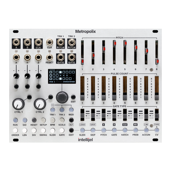
- Page 1 Metropolix Multitrack, Performance-Oriented Pitch, Gate and Mod Sequencer Manual (English) Firmware Version: 1.0.0.5 | Revision: 2021.02.14 (PRELIMINARY)
-
Page 2: Table Of Contents
TABLE OF CONTENTS COMPLIANCE INSTALLATION Installing Your Module Connecting an Optional Expander Module METROPOLIX OVERVIEW MANUAL CONVENTIONS FRONT PANEL OVERVIEW OUTPUTS INPUTS SECTIONS PITCH SLIDERS PULSE COUNT GATE TYPES SCREEN & TRACK BUTTONS SCREEN ENCODER EXIT HOME Screen 1 : Positions Overview HOME Screen 2 : Note Overview HOME Screen 3: Panel Values &... - Page 3 Enter and Configure Loopy Mode 1-Finger Loopy 2-Finger Loopy Stage Player Loopy Latching Muting Tracks and MOD Lanes GLOBAL SETTINGS SETUP Factory Menu SCALE Customizing SCALE Shortcuts TRACK SETTINGS ORDER Order Options Customizing ORDER Shortcuts LEN (LENGTH) SWING SLIDE TIME (TRACK) GATE Metropolix Manual...
- Page 4 Range Limits Interaction with Gate Modes and Ratchets CV TYPE = CV Value CV TYPE = Gate Toggle ALT BUTTONS LOAD Loading Presets SAVE Saving Presets Clearing Presets OUT A & B LIM (ACCUM LIMITS) TYPE (CV TYPE) Metropolix Manual...
- Page 5 CONTROL KNOBS Control Knob Destinations AUX INPUT SETTINGS AUX & MOD DESTINATIONS COPY & PASTE GATE STRETCHING - EXAMPLES CALIBRATION Entering Calibration Mode Calibrating Metropolix Outputs Calibrating Metropolix Inputs FACTORY RESET FIRMWARE UPDATES Firmware Change Log TECHNICAL SPECIFICATIONS ...
-
Page 6: Compliance
(2) this device must accept any interference received, including interference that may cause undesired operation. Changes or modifications not expressly approved by Intellijel Designs, Inc. could void the user’s authority to operate the equipment. Any digital equipment has been tested and found to comply with the limits for a Class A digital device, pursuant to part 15 of the FCC Rules. -
Page 7: Installation
INSTALLATION Intellijel Eurorack modules are designed to be used with a Eurorack-compatible case and power supply. We recommend you use Intellijel cases and power supplies. Before installing a new module in your case, you must ensure your power supply has a free power header and sufficient available capacity to power the module: ●... -
Page 8: Installing Your Module
Eurorack case. Ensure the red stripe on the cable lines up with the -12V pins on the bus board. On Intellijel power supplies the pins are labelled with the label “-12V” and a thick white stripe. Sometimes the connectors are shrouded, ensuring the cable can only be oriented in one direction. -
Page 9: Connecting An Optional Expander Module
Connecting an Optional Expander Module You can connect an Intellijel Gx (or Qx ) gate expander module to Metropolix to provide eight additional gate and trigger outputs, which you configure via the MX button on the Metropolix panel. -
Page 10: Metropolix Overview
● 8 separate and individual MODulation lanes are accessed via the MOD button. Each MOD lane has 8-stages of modulation values and its own playback ORDER, LENgth, and clock DIVision; and each lane is routable to one of Metropolix’ two assignable outputs or to dozens of internal destinations, allowing for some sophisticated and powerful self-modulation. -
Page 11: Manual Conventions
● Metropolix stores up to 64 preset configurations (in 8 banks of 8 presets), and all live settings are stored in EPROM, ensuring that your Metropolix will always power up exactly as you left it — even if you haven’t saved them to a preset. By default presets can change all the structural (menu-based) elements of your sequencer without overwriting the front panel controls, but full recall is also available. -
Page 12: Front Panel Overview
The Front Panel consists of numerous input and output jacks, plus a plethora of buttons, switches, knobs, and other such controllers. Each of these is described briefly below, though more detailed descriptions are contained later in the manual. Metropolix Manual... -
Page 13: Outputs
LED indicates the type of signal assigned to it. CLOCK OUT - Outputs a clock from Metropolix. A clock signal is output only when the sequencer is running. The output clock can run at any division of the input (whether internally... -
Page 14: Inputs
Y IN - A second AUX input for controlling Metropolix. It is functionally identical to the X IN . Z IN - A third AUX input for controlling Metropolix. It, too, is functionally identical to X IN . -
Page 15: Sections
[11] AUX IN Settings - Metropolix offers three user-assignable AUX inputs ( X , Y and Z ) for controlling the sequencer externally. Press an input’s corresponding button to assign an AUX destination on one or more tracks, and use the built-in attenuverter to dial in the desired amount of control. -
Page 16: Pitch Sliders
PITCH SLIDERS (SECTION 1) These sliders determine the default pitch value of each corresponding stage. Metropolix uses the position of these sliders as a starting point for determining the actual pitch output by each stage on each track. On a GLOBAL level: ●... - Page 17 Track Menu enables you to assign notes that are out of scale. NOTE: Metropolix offers the option of loading stored pitch values with a Preset in its SETUP menu. If you choose to load this data, then the pitch you hear may not match the sliders. Similarly if a...
-
Page 18: Pulse Count
In general, the type (and number) of gates generated while on a stage is determined by the GATE TYPE switches (described below). NOTE: Metropolix offers the option of loading switch positions with a Preset in its SETUP menu. If you choose to load this data, then the pulse count you hear may not match the switches. You can... -
Page 19: Gate Types
NOTE : Ratchets can create additional gates within the time frame of a single pulse. See RATCH more information about the relationship between ratchets and Gate Type. NOTE: Metropolix offers the option of loading switch positions with a Preset in its SETUP menu. If you choose to load this data, then the Gate Type you hear may not match the switches. -
Page 20: Screen & Track Buttons
EXIT button. SCREEN The contents of the screen change dynamically as you edit different Metropolix functions. Most editing screens are accessed by pressing one of the many buttons contained within the GLOBAL, TRACK, and STAGE sections of the panel, and will be discussed where appropriate. -
Page 21: Encoder
Indicates the value changes only if the ALT button is held when turning the encoder Indicates the parameter is assigned to one of the CTRL knobs (either 1” or a “2”), and can therefore not be changed by turning the encoder. Metropolix Manual... -
Page 22: Exit
● HOME Screen access : Press the EXIT button to access the top-level HOME Screens (described below), or to step backwards out of any Metropolix menus. Metropolix features several HOME Screens — each of which displays a different overview of Metropolix’ current configuration. Once at the HOME Screen level, rotate the encoder to cycle through the various screens . -
Page 23: Home Screen 1 : Positions Overview
HOME Screen 1 : Positions Overview The first HOME screen shows the current STAGE position (and its playback status) for Metropolix’ two note tracks and one of its MOD Lane. TRK 1 stages : Each of TRK 1’s eight stages is represented by a block. -
Page 24: Home Screen 2 : Note Overview
Stage EDIT function if the TRK 1 or TRK 2 button is lit, or the current MOD Lane selection/assignment if the MOD button is lit. Home Screen indicator : Solid line indicates this is the second of four Home Screens, which you access by rotating the encoder. Metropolix Manual... -
Page 25: Home Screen 3: Panel Values & Preset Overrides
Stage EDIT function if the TRK 1 or TRK 2 button is lit, or the current MOD Lane selection/assignment if the MOD button is lit. Home Screen indicator : Solid line indicates this is the third of four Home Screens, which you access by rotating the encoder. Metropolix Manual... -
Page 26: Home Screen 4: Mod Overview
MOD Lanes : These eight columns represent Metropolix’ eight MOD Lanes. As Metropolix plays, these columns indicate the value of each stage’s MOD voltage. 0V is represented by the dotted line in the middle of the column. As the voltage becomes more positive, the length of the gauge rising above the 0V line becomes longer. -
Page 27: Track Buttons
TRACK BUTTONS Metropolix is a multitrack sequencer. Two of the tracks ( TRK 1 and TRK 2 ) are designed for traditional note, gate, and CV sequencing, while an additional eight separate lanes of modulation are accessible via the MOD button. Specifically: ●... -
Page 28: Track Menu
To open and edit a Track/Lane Menu: Press Metropolix’ ALT button, followed by the button ( TRK 1 , TRK 2 or MOD ) whose menu you wish to edit. Turn the encoder to scroll through the available functions. -
Page 29: Track Menu Options For Tracks 1 & 2
Numerous examples that illustrate several ways that Gate Stretching extends your rhythmic options (when combined with other parameters) are given in Gate Stretching - Examples , later in the manual. Metropolix Manual... - Page 30 This is a variation on the ‘classic’ ratcheting effect, in that it ensures the ratchets always repeat at the same rate, but it allows for the number of ratchets to expand or contract with gate length. Metropolix Manual...
-
Page 31: Lane Menu Options For The Mod Lanes
With this function highlighted, click the encoder to reset all modulation stages on currently displayed MOD Lane (1 - 8). Init All Lane Defaults With this function highlighted, click the encoder to reset all modulation stages on all 8 MOD Lanes Metropolix Manual... -
Page 32: Transport Buttons
The RUN button (and the corresponding RESET jack, if configured as a RUN jack in the SETUP MENU ) will simultaneously start/stop playback of all three Metropolix tracks ( TRK 1 , TRK 2 and MOD ). You can, however, mute and unmute individual tracks (and even individual MOD Lanes), by holding the LOOPY button while pressing the TRACK button or MOD Lane button that you want muted. -
Page 33: Loopy (∞)
∞ Press the ( LOOPY ) button to activate Metropolix’s Loopy mode. Loopy enables you to interject a short, linear sub-loop into the current sequencer pattern, which will play either forward or backward, depending on the ORDER Screen’s Direction parameter. -
Page 34: Enter And Configure Loopy Mode
MOD Lanes. If the MOD button is lit when you press the LOOPY button, Metropolix automatically switches to TRK 1, making it the ‘Current’ track. Turn the encoder to set the desired number of LOOP PULSES (in number of pulses, or ‘Auto’). -
Page 35: 1-Finger Loopy
Lift your finger, then press and hold a different Stage button to shift the loopy region to begin at that stage. Release the held Stage button. Loopy returns to playing your original sequence at the point it would be at had Loopy not been triggered. Metropolix Manual... -
Page 36: 2-Finger Loopy
● If LOOP PULSES < the PULSE COUNT total of the stages within the loopy cycle, then loopy will cycle after the requested number of pulses, and before it reaches the final stage. In this situation, Loopy performs as if only 1-finger were used. Metropolix Manual... - Page 37 Press and hold any other combination of two Stage buttons to shift the loopy region to begin and end at those stages. Release the held Stage buttons. Loopy returns to playing your original sequence at the point it would be at had Loopy not been triggered. Metropolix Manual...
-
Page 38: Stage Player
● UPDATES: Any changes you make to a Stage’s settings (the PITCH SLIDER, for example) while the Stage button is being held will not be heard. In order to hear the changes, you must press the Stage button again after making the changes. Metropolix Manual... -
Page 39: Loopy Latching
When Loopy is latched, a lock icon appears in the Action Display at the bottom of the screen. To unlatch Loopy, navigate back to the LOOPY screen (if you’re not already on it), then press either the LOOPY button or the encoder. Metropolix Manual... -
Page 40: Muting Tracks And Mod Lanes
Lanes. To do so: Press and hold down the desired LOOPY button. The Action Display at the bottom of the Metropolix screen will say “MUTE TRK/LANE” and the three TRACK and eight STAGE/LANE buttons will light. While still pressing the LOOPY button, press a TRACK button to mute that track’s playback. -
Page 41: Global Settings
GLOBAL SETTINGS (SECTION 6) Although Metropolix is a three track sequencer, there are many parameters that apply to the entire unit, as a whole — and thus affect all Tracks at a global level. These are the “global settings,” and they are accessed by the set of three grey buttons to the right of the red Transport buttons: ●... -
Page 42: Setup
FUNCTION CHOICES DESCRIPTION Clock Internal Metropolix uses its own internal clock, which runs at the tempo set in the BPM field (accessed via the BPM button). External Metropolix uses an external clock patched into its CLK IN jack. Reset Input... - Page 43 VCA with a fast closing AD-type envelope. When set to ‘Clock,’ the sequencer must be running in order to transmit a clocked gated. Click the EXIT button to exit Tuner Mode. Metropolix Manual...
- Page 44 Instead, the front panel switch positions are always representative of what the sequence plays. This is ideal for those who wish to take full advantage of Metropolix’ hands-on, jam-oriented approach to sequencing. This is the factory default setting.
- Page 45 This is ideal for those who require different sequences/presets to use different AUX jack assignments. This is the factory default setting. Metropolix Manual...
- Page 46 ‘7’ immediately (without pressing the encoder). Show Pos. If desired, you can have Metropolix’ screen display a small position indicator, which (like the PITCH SLIDER LEDs) identifies which of the active track’s Stages is currently playing. This parameter...
- Page 47 TIP: To reset any SETUP MENU item to its default value, simply select it (highlighting it), and long-press the encoder. Metropolix Manual...
-
Page 48: Factory Menu
Metropolix’ Factory menu contains various housekeeping, test, and maintenance features. These modes are meant for use at (or by) Intellijel, and will likely never be needed in the field. To access the Factory Menu, highlight the Version number in the SETUP menu, then press down and hold the MOD button while pressing the encoder. -
Page 49: Bpm
For example, if you feed a 24ppq clock directly into Metropolix’s CLK IN jack from an external device, then choosing /6 will result in a standard sixteenth note pulse, and the BPM will be automatically calculated and displayed in the BPM field. - Page 50 ( EXT CLOCK DIV ) to achieve the desired tempo. This is likely necessary only if, for example, you’re feeding Metropolix with a clock (such as 24 ppq or 48 ppq) sent from an external device. The actual tempo (based on sixteenth note pulses) is displayed in the BPM field (which is not directly editable).
-
Page 51: Scale
This button accesses Metropolix’s SCALE screen, which defines the scale (and root) used by Metropolix. The scales available in Metropolix correspond to those in other Intellijel products, such as Scales and Tête . There are two main parameters accessible by the button, and you can toggle between them by pressing the Encoder button: ●... - Page 52 MAJOR PENTATONIC CHINESE MIXOLYDIAN SUPER LOCRIAN MINOR PENTATONIC HIRAJOSHI MINOR (AEOLIAN) HARMONIC MINOR WHOLE TONE IN-SEN LOCRIAN LOCRIAN NAT-6 WHOLE HALF DIMINISHED KUMOI MELODIC MINOR IONIAN #5 (AUG) HALF WHOLE DIMINISHED PELOG DORIAN b2 DORIAN #4 MINOR BLUES Metropolix Manual...
-
Page 53: Customizing Scale Shortcuts
Stage buttons to save the SCALE/ROOT combination. The Stage buttons will all blink once to indicate the save operation is complete. Your SCALE/ROOT combination is saved, and can be recalled any time by holding down the SCALE button and short-pressing the desired Stage button. Metropolix Manual... -
Page 54: Track Settings
(Track) GATE button - Opens the TRACK GATE screen, which sets the selected track’s default gate length for all the pulses (and ratchets) in the current track. NOTE: Track Gate is not available on the MOD Lanes. Metropolix Manual... -
Page 55: Order
There are two main parameters accessible by the button: ● PLAY ORDER : The upper parameter defines the order in which any enabled stages will play back. Metropolix features many order choices, as discussed in Order Options , later. -
Page 56: Order Options
Forward: 1 4 7 2 5 8 3 6 | 1 4 7 2 5 8 3 6 | etc... Reverse: 8 5 2 7 4 1 6 3 | 8 5 2 7 4 1 6 3 | etc.. Metropolix Manual... - Page 57 Forward: 4 5 3 6 2 7 1 8 | 4 5 3 6 2 7 1 8 | etc... Reverse: 5 4 6 3 7 2 8 1 | 5 4 6 3 7 2 8 1 | etc... Metropolix Manual...
- Page 58 (and will) repeat. Because every stage is randomly selected, sequences do not cycle and do not automatically reset. Metropolix Manual...
-
Page 59: Customizing Order Shortcuts
Stage buttons to save the PLAY ORDER/DIRECTION combination. The screen will indicate that the shortcut has been saved. Your PLAY ORDER/DIRECTION combination is saved, and can be recalled any time by holding down the ORDER button and short-pressing the desired Stage button. Metropolix Manual... -
Page 60: Len (Length)
This setting offsets Metropolix’ definition of “Stage 1.” For example, if the OFFSET = ‘1’ , then Metropolix starts (and resets) playback on Stage 2, rather than Stage 1 (since the starting stage is offset by a count of one). - Page 61 Applying a Stage Offset lets you define which of the 8 stages is considered the “first stage” when a sequence is reset. To reset all LENGTH parameters back to their default values, long-press the encoder. Metropolix Manual...
-
Page 62: Div
If the PULSE DIV parameter is highlighted instead, press the encoder to return encoder control to the CLOCK DIV parameter. NOTE: If Metropolix is clocking to an external source, then two different clock dividers are at work. One clock divider, called the EXT CLOCK DIV , is accessible via the... - Page 63 Pulse Division (from 1 to 8). SHORTCUT: Hold down the DIV button and press one of the first eight stage buttons to set the PULSE DIV value directly. To reset all DIV parameters back to their default values, long-press the encoder. Metropolix Manual...
-
Page 64: Swing
● SWING : Swing delays each odd numbered clock pulse by a percentage of the current clock interval. With a value of 50%, no swing is applied (straight time). The more you increase the swing percentage above 50% the more your music will have a ‘swing’ feel. Metropolix’ supports swing percentages from 50% to 78%. -
Page 65: Slide Time
In addition, to get that classic ‘acid’ sound, the stage on which the SLIDE function is enabled will automatically hold its gate high for all of its pulses (as if you switched its GATE TYPE to ‘HOLD’). Metropolix Manual... - Page 66 SLIDE AMOUNT value directly. Press the encoder to toggle the slide SLIDE TYPE between ‘Analog’, ‘Tempo’ and ‘Acid’. This determines the type of slide, as described above. To reset the SLIDE parameters back to their default values, long-press the encoder. Metropolix Manual...
-
Page 67: (Track) Gate
(accessed via the (Stage) GATE button If highlighted (the symbol is beside the GATE SCALE parameter), turn the encoder to set the scaling. If the GATE LENGTH parameter is highlighted instead, press the encoder to move encoder control to the GATE SCALE parameter. Metropolix Manual... - Page 68 Now, change only the TRACK GATE screen’s GATE SCALE from 100% to 50%. The gate output of this sequence looks like ROW 3. Finally, change only the TRACK GATE screen’s GATE LENGTH from 50% to 75%. The gate output of this sequence looks like ROW 4. Metropolix Manual...
- Page 69 GATE SCALE value directly, with Stage buttons 1-8 setting GATE SCALE times of 1, 15, 30, 45, 60, 75, 90, and 100%, respectively. To reset all TRACK GATE parameters back to their default values, long-press the encoder. Metropolix Manual...
-
Page 70: Stage Buttons
STAGE BUTTONS (SECTION 8) Besides allowing numerous track-based edits (discussed earlier in TRACK SETTINGS ), Metropolix also enables you to edit individual STAGES within each track. This is the purpose of the Stage buttons, described here. In general, you need to: Press the Track button ( TRK 1 or TRK 2 ) to select which track’s stages you wish to edit. -
Page 71: Slide
The screen will also update to show that slide settings for each of the eight stages. In the following example, Stages 5 and 6 are set to SLIDE. NOTE: If Show Pos. = ON in the SETUP menu, then an underline appears beneath the currently playing stage. Metropolix Manual... -
Page 72: Skip
“Skip Invert” as the destination of a CTRL knob, AUX Input ( X , Y or Z ) input or a MOD Lane. In the previous example, an inverted skip would result in Stages 1, 2, 4, 7 and 8 being skipped. Metropolix Manual... -
Page 73: Pitch
○ Push the encoder to set the current stage’s PITCH OVERRIDE to the PITCH SLIDER’S position at that stage. ○ Hold ALT and push the encoder to set all eight stage’s PITCH OVERRIDE values to their corresponding PITCH SLIDER positions. Metropolix Manual... - Page 74 ● Hold the EDIT button and turn the encoder to change the pitch override across all stages simultaneously. ● Long-press the encoder to remove the pitch override from the current stage . ● Hold the EDIT button and long-press the encoder to remove pitch overrides from every stage. Metropolix Manual...
-
Page 75: (Stage) Gate
(a “hold”), and does not go low before the sequence advances to the next stage. NOTE: Setting a per-stage GATE OVERRIDE will not affect any cumulative transposition that might be assigned. Also, any gate GATE SCALE function (accessed via the track’s GATE button) will still apply to any per-stage gate length overrides. Metropolix Manual... - Page 76 ● Hold the EDIT button and turn the encoder to change the gate length override across all stages simultaneously. ● Long-press the encoder to remove the gate length override from the current stage . ● Hold the EDIT button and long-press the encoder to remove the gate length overrides from all stages . Metropolix Manual...
-
Page 77: Ratch
Repeat Steps 3-4 for any other stages to which you wish to assign ratchets. As long as you remain on the RATCH edit screen, any of the eight stage buttons to which you’ve assigned a ratchet (that is, a value greater than 1) will light cyan Metropolix Manual... -
Page 78: Ratcheting With Gate Stretching = Off
Group 2 (middle three rows) illustrates the same conditions at Group 1, except the DIV screen’s PULSE DIV is set to ‘/2.’ Group 3 (bottom three rows) illustrates the effect of different Ratchet values when GATE TYPE = SINGLE (in which case PULSE DIV has no effect). Metropolix Manual... -
Page 79: Ratcheting With Gate Stretching = On
It can yield very interesting rhythmic variations but may not sonically resemble “traditional” ratchets. The following example shows the relationship between number of RATCHETS , GATE TYPE, PULSE DIV , and a Stage’s PULSE COUNT when Gate Stretching = ON and Ratchets = Multiply in the TRACK MENU Metropolix Manual... - Page 80 The following example shows the relationship between the number of RATCHETS , GATE TYPE, PULSE DIV , and a Stage’s PULSE COUNT when Gate Stretching = ON and Ratchets = Pulse in the TRACK MENU Metropolix Manual...
- Page 81 The following example shows the relationship between RATCHETS , GATE TYPE, PULSE DIV , and a Stage’s PULSE COUNT when Gate Stretching = ON and Ratchets = Gated in the TRACK MENU Metropolix Manual...
-
Page 82: Prob
PULSE COUNT = 4 and the PROBABILITY AMOUNT is 50%, then there is a 50% chance that the stage’s first pulses will play, and then a 50% chance that the stage’s next pulse will play, etc. Metropolix Manual... - Page 83 ● Long-press the encoder to reset the current stage to its default PROBABILITY AMOUNT (‘100%’) and PROBABILITY TARGET (‘Stage’). ● Hold the EDIT button and long-press the encoder to reset all stages to their default PROBABILITY AMOUNTS (‘100%’) and PROBABILITY TARGETS (‘Stage’). Metropolix Manual...
-
Page 84: Accum
‘Stage’ : Applies the transposition amount each time the stage is played. This is the default selection. ‘Pulse’ : Applies the transposition amount each time a pulse is played. ‘Ratch’ : Applies the transposition amount each time a ratchet event is played. Metropolix Manual... - Page 85 ● Long-press the encoder to reset the current stage to its default TRANSPOSE AMOUNT (0 semitones) and default Transpose Trigger (Stage). ● Hold the EDIT button and long-press the encoder to reset all stages to their default TRANSPOSE AMOUNT (0 semitones) and default TRANSPOSE TRIGGER (Stage). Metropolix Manual...
-
Page 86: Range Limits
Interaction with Gate Modes and Ratchets Cumulative transpositions interact with other Metropolix features as follows: ● RESET : When a sequence is RESET, all accumulated transpositions reset to their starting pitches (the PITCH SLIDER values) and will begin to re-accumulate on the second pass through the sequence. - Page 87 Press EDIT + CV to access the per-stage CV Lane. This is a per-track sequencer “lane” that generates an additional control voltage on each stage. You can control external gear by sending the CV lane out one of Metropolix’s two assignable outputs ( A or B ), as described in OUT A & B To edit a Stage’s CV value, press the Stage button corresponding to the Stage you wish to edit.
-
Page 88: Cv Type = Cv Value
Note that, if a Stage is only one pulse in length, then ‘pRmp’ and ‘sRmp’ have the same effect. NOTE: To assign all 8 stages to the same ramp setting, hold down the EDIT button while pressing the encoder — this assigns all 8 stages at once, rather than just the current stage. Metropolix Manual... - Page 89 ● Hold the EDIT button and long-press the encoder to reset the control voltage to 0V on every stage. REMINDER : In order to hear the effect of the CV Lane, you must assign it to one of Metropolix’ two assignable outputs ( A or B ), as discussed in OUT A &...
-
Page 90: Cv Type = Gate Toggle
6. Long-press the encoder to reset the current stage gates to their low (0V) values. REMINDER : In order to hear the effect of the CV Lane, you must assign it to one of Metropolix’ two assignable outputs ( A or B ), as discussed in OUT A &... -
Page 91: Alt Buttons
● the parameter to which each AUX input (X, Y and Z) is assigned. Although Metropolix saves the previous four data types in a preset, you can choose whether or not you want to load this data when you load a patch. Not loading the Pitch and Switch values ensures the front panel PITCH SLIDERS, PULSE COUNT and GATE TYPE switches always always reflect what the sequence plays back. -
Page 92: Loading Presets
Make sure the ACTION parameter is set to ‘Load.’ Pressing the encoder toggles between the ‘Load’ and ‘Queue’ options. Press the Stage button (1-8) that corresponds to the preset you wish to load. The preset loads, resetting the sequence, and the screen flashes a message to confirm the preset has loaded. Metropolix Manual... - Page 93 If the LEN screen’s Pulses parameter is set to anything other than ‘Auto,’ then the queued preset loads when the sequence resets. NOTE 2: Queued Presets will also load when Metropolix is stopped, ensuring they are loaded prior to restarting the sequencer.
-
Page 94: Save
● the parameter to which each AUX input (X, Y and Z) is assigned. Although Metropolix saves the previous four data types in a preset, you can choose whether or not you want to load this data when you load a patch. Not loading the Pitch and Switch values ensures the front panel PITCH SLIDERS, PULSE COUNT and GATE TYPE switches always always reflect what the sequence plays back. -
Page 95: Saving Presets
Stage buttons contain presets. Dimly lit Stage buttons are empty. A flashing Stage button indicates the most recently saved preset (if you don’t switch banks). Press the Stage button (1-8) that corresponds to the preset you wish to clear. The screen flashes a message to confirm your preset has been saved. Metropolix Manual... -
Page 96: Out A & B
B The third and fourth Stage buttons in ALT Mode are used to assign a function to Metropolix’s OUT A and OUT B jacks. Specifically, for each output, you can assign the type of signal sent to the output jack, and the track from which the signal is sent. - Page 97 For example, if you assigned a TRK 1 parameter to OUT A and TRK 2 parameter to OUT B, then Trk Out Swap would “swap” the assignments, such that the TRK 1 parameter is sent to OUT B; and the TRK 2 parameter is sent to OUT A. Metropolix Manual...
- Page 98 A (?) does not appear next to the name of the currently applied option. Press the encoder to confirm your choice. To reset all Output Assignment parameters back to their default values, long-press the encoder. Metropolix Manual...
-
Page 99: Clk
CLK output assignment screen, which contains two parameters: ● CLK OUT : This divides Metropolix’ global clock source (as set with the BPM button) by a factor of /1 to /256, prior to sending it to the CLK OUT jack. - Page 100 (from /1 to /256). With the CLK OFFSET field highlighted, turn the encoder to set the desired clock offset (from ’0’ to ’one less than the CLK OUT value’). To reset all parameters back to their default values, long-press the encoder. Metropolix Manual...
- Page 101 Connecting an Optional Expander Module “MX” is an acronym for “ M etropolix e X pander,” and Metropolix supports use of either the Gx or Qx gate expander modules. Either of these expanders adds additional gate, clock, reset and run outputs to the Metropolix, and operates in one of four modes, selectable via this button.
- Page 102 MOD Lane selected by the MX ASSIGN parameter. These gate outputs are not affected by Metropolix’ Gate Length settings. The ‘Mod Stg Num’ setting enables you to trigger/gate external events that are synchronized with a particular stage number on a particular MOD Lane.
- Page 103 8 MOD Lanes is the Gx/Qx output source. If MX EXPANDER = ‘Mod Clocks’, then MX ASSIGN value is fixed to ‘1-8’, meaning clocks from each of Metropolix’ eight MOD Lanes will appear the eight Gx/Qx outputs (using whatever CLOCK DIV settings were selected for each lane’s DIV screen).
- Page 104 6-pin I2C connector on Metropolix, as described in Connecting an Optional Expander Module IMPORTANT !!! : Always power down both the Mx and Metropolix before connecting or disconnecting an I2C cable between them. Press the ALT button followed by the (Stage 6) button to open the MX (Metropolix Expander) output assignment screen.
-
Page 105: Lim (Accum Limits)
With the UPPER LIMIT field highlighted, turn the encoder to set the maximum amount of upward transposition (in scale degrees). With the LOWER LIMIT field highlighted, turn the encoder to set the maximum amount of downward transposition (in scale degrees). To reset all LIM parameters back to their default values, long-press the encoder. Metropolix Manual... -
Page 106: Type (Cv Type)
The change is applied immediately, and you will now be able to edit the CV Lane (accessed by pressing EDIT followed by the CV button). To reset CV TYPE back to its default setting, long-press the encoder. Metropolix Manual... -
Page 107: The Mod Lanes
THE MOD LANES Metropolix features eight independent and separate MOD Lanes — each with 8 different voltage stages, and each capable of being routed to either of the two assignable OUT jacks ( A or B ), or to many of Metropolix’... -
Page 108: Editing Stage Voltage In A Mod Lane
Editing Stage Voltage in a MOD Lane Each MOD lane has 8 different voltage stages, corresponding to the 8 Metropolix stages. To assign a voltage to each stage in a Mod Lane: As described above, with the MOD button lit, press EDIT + the STAGE button (1-8) corresponding to the MOD Lane you wish to edit. - Page 109 NOTE : You can mute and unmute individual MOD Lanes by holding down the LOOPY button while pressing the MOD Lane button (1-8) corresponding to the lane you want muted. For more information, see Muting Tracks and MOD Lanes , earlier in the manual. Metropolix Manual...
-
Page 110: Editing Gates In A Mod Lane
For example, if you assign MOD Lane 1 to ‘Direction ⎍’ then the MOD Stage Edit Screen displays 8 dots. If you press Stage button 5 (making the 5th circle white), then the playback direction of the destination track will reverse every time stage 6 plays. Metropolix Manual... -
Page 111: Assigning A Mod Lane To An Out Jack
Each MOD Lane can have its own destination. You can send a MOD Lane to an output jack, or to an Internal parameter (as described in Assigning a MOD Lane to an Internal Parameter To assign a MOD Lane to one of Metropolix’ two output jacks, select ‘Mod’ as the OUTPUT <n> source in either the OUT or OUT assignment screen, discussed earlier in OUT A &... -
Page 112: Assigning A Mod Lane To An Internal Parameter
Each MOD Lane can have its own destination. You can send a MOD Lane to an Internal parameter, or to one of Metropolix’ two output jacks ( A or B ) (as described in Assigning a MOD Lane to an... - Page 113 Turning an encoder edits the highlighted parameter. Pressing the encoder toggles highlighting to the other parameter for editing. NOTE: If a MOD Lane is routed to one of Metropolix’ two OUT jacks (as described in Assigning a MOD Lane to an OUT Jack ), then a small indicator appears, as shown above.
- Page 114 With the MOD PARAM field highlighted, turn the encoder to select the Metropolix parameter you wish to control with the currently indicated MOD Lane. Press the encoder to confirm your choice. The MOD Lane destination parameter is set, and your choice is indicated in the Action Display at the bottom of the screen Press the encoder to toggle highlighting to the MOD ASSIGN field, highlighting it.
-
Page 115: Assigning Order, Length & Clock Div To Mod Lanes
NOTE: The SWING, SLIDE and GATE timings do not apply to the MOD Lanes, and are thus unavailable when editing a MOD Lane. From this screen, you can press the stage buttons (no modifier) to select the track you want to assign. Metropolix Manual... -
Page 116: Control Knobs
The two programmable CTRL knobs further enhance these capabilities — allowing you to control any two Metropolix parameters with a twist of the wrist. Each CTRL knob has its own CTRL SETTINGS screen (accessed by pushing the CTRL knob’s corresponding black button), from which you select the parameter and track(s) that you want the knob to control. - Page 117 This parameter displays which Track you wish to control. To set it: a) Press the encoder to highlight the CTRL ASSIGN field. b) Rotate the encoder to select either TRK 1 , TRK 2 , or TRK 1+2 . c) Press the encoder to apply your selection. Metropolix Manual...
- Page 118 This indicates that the parameter is controlled by the CTRL knob, and not the encoder. A “1” indicates the CTRL 1 knob, and a “2” indicates the CTRL 2 knob. To reset an CTRL knob back to its default value (i.e. NO assignment), long-press the encoder. Metropolix Manual...
-
Page 119: Control Knob Destinations
Turning the knob clockwise from the noon position increases the pitch of all stages on the destination track(s) after the quantization stage. Turning the knob counterclockwise from the noon position decreases the post-quantization pitch. Metropolix Manual... - Page 120 Turning the knob counterclockwise from the noon position results in normal (uninverted) SKIP playback. “Skip Invert” is a convenient way to set up and trigger split Metropolix Manual...
- Page 121 8 stages. Turning the knob counterclockwise from the noon position causes the TRK 1 and TRK 2 output assignments to appear at their designated output jacks. Metropolix Manual...
-
Page 122: Aux Input Settings
AUX INPUT SETTINGS SECTION 11 X, Y and Z are three user-configurable control voltage inputs for Metropolix — each with an associated attenuverter — which allows you to externally control and modulate an extensive number of sequence parameters, per-track. An input voltage of ±5V is required to span the full range of an... - Page 123 This parameter displays which Track you wish to control. To set it: a) Press the encoder to highlight the AUX ASSIGN field. b) Rotate the encoder to select either TRK 1 , TRK 2 , or TRK 1+2 . c) Press the encoder to apply your selection. Metropolix Manual...
- Page 124 ( 1 , 2 , or 1+2 ) you wish to control with the AUX input, then press the encoder to confirm your track selection. The incoming AUX CV will now affect the assigned parameter on the chosen track(s). To reset an AUX assignment back to its default value (i.e. NO assignment), long-press the encoder. Metropolix Manual...
-
Page 125: Aux & Mod Destinations
GATE LENGTH length (as set with the (TRACK) GATE button) is used. Positive voltages increase the Gate Length, until the maximum value is reached (“100%”). Negative voltages decrease the Gate Length, until the minimum value is reached (“rest”). Metropolix Manual... - Page 126 Positive voltages increase the pitch of all stages on the destination track(s) after the quantization stage, while negative voltages decrease the post-quantization pitch. Pitch Post ±5V Positive voltages increase the pitch of all stages on the destination track(s) after the quantization stage. This means it’s possible (and Metropolix Manual...
- Page 127 GATE TYPE = MULTI in order to hear the modulation’s effect. Pulses Len ±5V Changes the Length (in pulses) of the destination track(s). Specifically, at 0V, it plays the number of pulses set by the LEN screen’s PULSES parameter. Positive voltages increase the number of pulses in the Metropolix Manual...
- Page 128 Slider Range ±5V Changes the octave range of the PITCH SLIDERS. Specifically, at 0V, the PITCH SLIDERS cover the octave range set by the Slider Octaves setting in the TRACK MENU. Positive voltages increase the octave Metropolix Manual...
- Page 129 This enables you to create elaborate sequence variations and rhythms that can extend beyond the various permutations available with the 8 stages. When the gate is low, the TRK 1 and TRK 2 output assignments appear at their designated output jacks. Metropolix Manual...
-
Page 130: Copy & Paste
For example, if you wish to copy TRK 1’s DIV setting to TRK 2, you would press the DIV button to tell Metropolix what parameters you’ll be copying. Hold down the Track button ( TRK 1 or TRK 2 ) corresponding to the Track whose settings you wish to copy from. - Page 131 The screen flashes a message to confirm the copied Mod Lane has been pasted. You can copy one MOD Lane to multiple MOD Lanes by continuing to hold the EDIT button and the “Copy From” Lane button while pressing different Lane destination buttons. Metropolix Manual...
-
Page 132: Gate Stretching - Examples
It assumes the TRACK GATE screen’s Gate parameter is set to 75%, and there are no per-stage overrides. It also assumes a 3-stage, linear, forward playing sequence — with four pulses on Stage 1, two pulses on Stage 2, and three pulses on Stage 3. Metropolix Manual... - Page 133 Row 7 & 8 : Here, with GATE TYPE = MULTI, we are dividing the pulse by /1. This results in a new pulse being generated every clock pulse. Therefore, it doesn’t matter whether Gate Stretching is on or off, because each note is one clock pulse long, resulting in identical gate lengths. Metropolix Manual...
-
Page 134: Calibration
CALIBRATION Metropolix is calibrated at the factory prior to shipment, so it’s unlikely you’ll ever need to perform any custom calibration. But if you do, these instructions (along with an external voltage meter) are all you need to calibrate it. -
Page 135: Calibrating Metropolix Outputs
Calibrating Metropolix Outputs You can calibrate all four of Metropolix’ variable outputs ( TRK 1 PITCH , TRK 2 PITCH , OUT A , OUT B ) using the same technique. TIP : If you make a mistake at any point during the following calibration procedure, you can scroll to the bottom of the Calibration menu, select Reload All , and press the encoder. -
Page 136: Calibrating Metropolix Inputs
Calibrating Metropolix Inputs You can calibrate all three of Metropolix’ variable inputs ( X , Y , and Z ) using the same technique.To Calibrate Tête’s inputs: TIP : If you make a mistake at any point during the following calibration procedure, you can scroll to the bottom of the Calibration menu, select Reload All , and press the encoder. -
Page 137: Factory Reset
Metropolix’ global, track, and stage parameters are all reset, along with the CTRL knob, AUX input, OUT and MOD assignments, custom shortcuts, etc. NOTE: Alternately, you can perform a Factory Reset by turning off power to the Metropolix then hold the SETUP button down while powering the unit back on. -
Page 138: Firmware Updates
Click the Instructions button to read specific instructions for updating your module. Metropolix’s current firmware is displayed on the screen during boot. If the module is already powered on, you can see it’s firmware version in the global SETUP MENU: Press the SETUP button to view the SETUP MENU.
Need help?
Do you have a question about the Metropolix and is the answer not in the manual?
Questions and answers